Page 1100 of 2890
B4M0051
7. Full Wheel Cap
A: REMOVAL
Pry off the full wheel cap with a wheel cap remover inserted
between openings in the cap.
B: INSTALLATION
Align the valve hole in the wheel cap with the valve on the
wheel and secure the wheel cap by tapping four points by
hand.
8. Steel Wheel and Tire
1) Deformation or damage on the rim can cause air leak-
age. Check the rim flange for deformation, crack, or
damage, and repair or replace as necessary.
2) Take stone, glass, nail etc. off the tread groove.
G4M0297
3) Replace tire:
�when large crack on side wall, damage or crack on
tread is found.
�when the“tread wear indicator”appears as a solid
band across the tread.
CAUTION:
�When replacing a tire, make sure to use only the
same size, construction and load range as originally
installed.
�Avoid mixing radial, belted bias or bias tires on the
vehicle.
49
4-2SERVICE PROCEDURE
7. Full Wheel Cap - 8. Steel Wheel and Tire
Page 1107 of 2890
14. Replacement of Front FTJ and BJ
Boots
A: REMOVAL
1) Disconnect ground cable from battery.
2) Jack-up vehicle, support it with safety stands (rigid
rocks), and remove front wheel cap and wheels.
NOTE:
Do not remove axle nut.
3) Remove stabilizer link.
4) Disconnect transverse link from housing.
G4M0279
5) Remove spring pin which secures transmission spindle
to FTJ.
CAUTION:
Use a new spring pin.
6) Remove FTJ and BJ boot from drive shaft.
B: INSTALLATION
1) Install FTJ and BJ boots to drive shaft.
G4M0279
2) Install FTJ on transmission spindle and drive spring pin
into place.
CAUTION:
Always use a new spring pin.
3) Connect transverse link to housing.
4) Install stabilizer link.
53
4-2SERVICE PROCEDURE
14. Replacement of Front FTJ and BJ Boots
Page 1118 of 2890
 Remove steering wheel nut, then draw out steering
wheel from shaft using steering puller.
G4M0086
5) Remove universal joint bolts and then remove universal
joint.
CAUTION:
Scribe alignment")
G5M0332
4) Remove steering wheel nut, then draw out steering
wheel from shaft using steering puller.
G4M0086
5) Remove universal joint bolts and then remove universal
joint.
CAUTION:
Scribe alignment marks on universal joint so that it can
be reassembled at the original serration.
6) Remove trim panel under instrument panel.
7) Disconnect connectors for ignition switch and combina-
tion switch wiring harness under instrument panel.
B4M0127A
8) Remove the two bolts under instrument panel securing
steering shaft.
9) Pull out steering shaft assembly from hole on toe board.
CAUTION:
Be sure to remove universal joint before removing
steering shaft assembly installing bolts when remov-
ing steering shaft assembly or when lowering it for
servicing of other parts.
B4M0555
B: DISASSEMBLY
Remove the four screws securing upper and lower steer-
ing column covers, and the two screws securing combina-
tion switch, then remove related parts.
NOTE:
Steering column assembly can not to be disassembled.
11
4-3SERVICE PROCEDURE
2. Tilt Steering Column
Page 1124 of 2890
G4M0101
9) Disconnect pipes C and D from pipe of gearbox.
CAUTION:
Be careful not to damage these pipes.
NOTE:
Disconnect upper pipe D first, and lower pipe C second.
G4M0102
10) Remove clamp bolts securing gearbox to
crossmember, and remove gearbox.
B4M0132A
B: DISASSEMBLY
1) Disconnect four pipes from gearbox.
2) Secure gearbox removed from vehicle in vice using ST.
ST 926200000 STAND
CAUTION:
Secure the gearbox in a vice using the ST as shown.
Do not attempt to secure it without this ST.
3) Remove tie-rod end and lock nut from gearbox.
G4M0104
4) Remove small clip from boot using pliers, and move
boot to tie-rod end side.
G4M0105
5) Remove boot together with large clips.
17
4-3SERVICE PROCEDURE
3. Steering Gearbox (Power Steering System) [LHD model]
Page 1125 of 2890
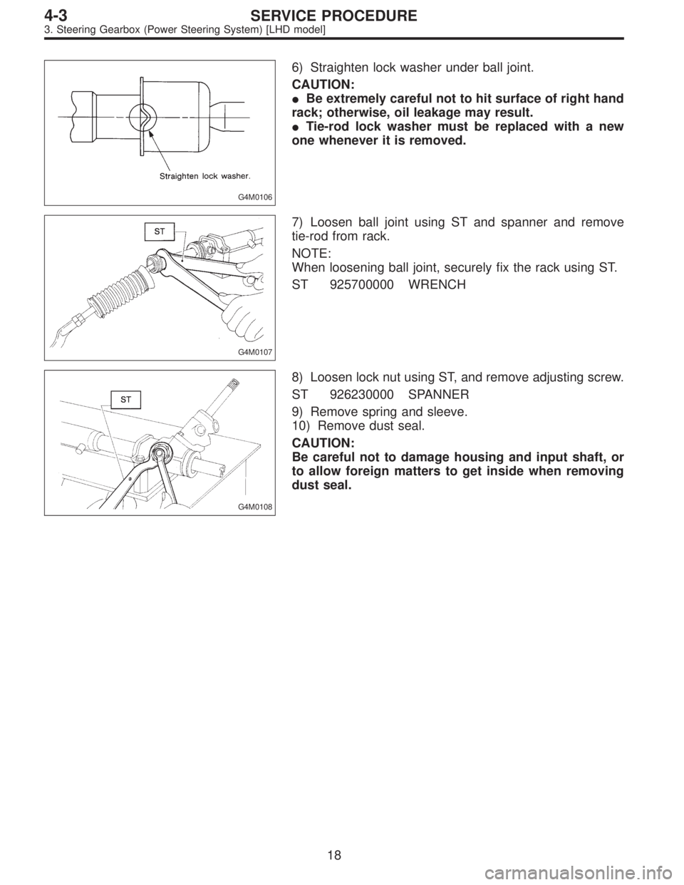
G4M0106
6) Straighten lock washer under ball joint.
CAUTION:
�Be extremely careful not to hit surface of right hand
rack; otherwise, oil leakage may result.
�Tie-rod lock washer must be replaced with a new
one whenever it is removed.
G4M0107
7) Loosen ball joint using ST and spanner and remove
tie-rod from rack.
NOTE:
When loosening ball joint, securely fix the rack using ST.
ST 925700000 WRENCH
G4M0108
8) Loosen lock nut using ST, and remove adjusting screw.
ST 926230000 SPANNER
9) Remove spring and sleeve.
10) Remove dust seal.
CAUTION:
Be careful not to damage housing and input shaft, or
to allow foreign matters to get inside when removing
dust seal.
18
4-3SERVICE PROCEDURE
3. Steering Gearbox (Power Steering System) [LHD model]
Page 1138 of 2890
 Remove flare nuts from control valve of gearbox
assembly, and disconnect upper and lower hoses B and A.
CAUTION:
�Always disconnect hoses B and A in that order.
�Be careful not to damage the hoses")
9) Remove flare nuts from control valve of gearbox
assembly, and disconnect upper and lower hoses B and A.
CAUTION:
�Always disconnect hoses B and A in that order.
�Be careful not to damage the hoses during removal.
10) Remove bolts securing gearbox to crossmember, and
detach gearbox.
G4M0788
B: DISASSEMBLY
1) Disconnect four pipes from gearbox.
2) Secure gearbox removed from vehicle in vice using ST.
ST 926200000 STAND
CAUTION:
Secure the gearbox assembly in a vice using the ST as
shown. Do not attempt to secure it without this ST.
G4M0789
3) Pry off clip from outer end of boot, and slide boot toward
tie-rod end.
G4M0790
4) Using ST, remove lock wire from inner end of boot, and
remove boot.
ST 927590000 WRENCH
G4M0791
5) Extend rack approximately 40 mm (1.57 in) out. Unlock
lock wire at lock washer on each side of tie-rod end using
a standard screwdriver.
CAUTION:
Be careful not to scratch rack surface as oil leaks may
result.
31
4-3SERVICE PROCEDURE
4. Steering Gearbox (Power Steering System) [RHD model]
Page 1149 of 2890
G4M0137
B: DISASSEMBLY
1. VALVE ASSEMBLY
1) Loosen two bolts securing valve assembly.
G4M0138
2) Carefully draw out input shaft and remove valve assem-
bly.
G4M0139
3) Draw out pinion and valve assembly from valve
housing, as necessary, using pipe of I.D. 44 to 46 mm (1.73
to 1.81 in) and a press.
G4M0140
2. RACK ASSEMBLY
1) Slide mounting rubber to expose slit.
G4M0141
2) Rotate rack stopper in the direction of arrow using ST
until the end of circlip comes out of stopper, then rotate it
in the opposite direction, and pull out circlip.
ST 926340001 WRENCH
42
4-3SERVICE PROCEDURE
5. Control Valve (Power Steering Gearbox) [LHD model]
Page 1152 of 2890
 Fit pinion and valve assembly into valve housing.
NOTE:
Apply ATF DEXRON II to outer diameter surface of input
shaft and outer surface of valve body seal ring, and pay
special attenti")
�Installation
1) Fit pinion and valve assembly into valve housing.
NOTE:
Apply ATF DEXRON II to outer diameter surface of input
shaft and outer surface of valve body seal ring, and pay
special attention not to damage seal when inserting pinion
and valve assembly.
G4M0149
2) Secure valve assembly to ST1 and ST2.
3) Put ST3 over pinion, and insert oil seal, then force-fit oil
seal into housing using ST4.
NOTE:
�Apply ATF DEXRON II to oil seal and ST3, being care-
ful not to damage oil seal lip.
�Push oil seal until ST3 contacts housing end face.
4) Remove ST3, and fit backing washer.
ST1 926370000 INSTALLER A
ST2 927630000 STAND BASE
ST3 926360000 INSTALLER A
ST4 927620000 INSTALLER B
G4M0150
5) Force-fit ball bearing using ST3.
ST1 926370000 INSTALLER A
ST2 927630000 STAND BASE
ST3 927640000 INSTALLER B
NOTE:
Be careful not to tilt ball bearing during installation.
6) Install snap ring using snap ring pliers.
NOTE:
Rotate snap ring to check for proper installation.
G4M0151
3. RACK HOUSING OIL SEAL AND BACK-UP
WASHER
�Removal
Insert a round rod [26—27 mm (1.02—1.06 in) dia.] from
pinion housing side and remove oil seal and back-up
washer by hammering the rod.
NOTE:
�Discard removed oil seal and back-up washer.
�Apply the unchamfered end of remover to back-up
washer.
45
4-3SERVICE PROCEDURE
5. Control Valve (Power Steering Gearbox) [LHD model]

 Disconnect ground cable from battery.
2) Jack-up vehicle, support it with safety stands (rigid
rocks), and remove front wheel cap and wheels.
NO")
 Disconnect pipes C and D from pipe of gearbox.
CAUTION:
Be careful not to damage these pipes.
NOTE:
Disconnect upper pipe D first, and lower pipe C second.
G4M0102
10) Remove clamp bolts se")
 Loosen two bolts securing valve assembly.
G4M0138
2) Carefully draw out input shaft and remove valve assem-
bly.
G4M0139
3) Draw out pinion and valve assemb")