Page 1154 of 2890

�After fitting cover, check air passage hole for clogging.
If clogged, open by removing grease from the hole.
�Check rack shaft for damage.
�Apply ATF DEXRON II to this ST and surface of piston
ring to prevent seal from being damaged.
G4M0155
4) Insert rack assembly into rack housing from cylinder
side, and remove ST after it has passed completely
through oil seal.
NOTE:
Before inserting rack assembly, apply a coat of ATF
DEXRON II to surfaces of ST and rack piston.
ST 926390001 COVER & REMOVER
G4M0156
5) Fit ST1 and ST2 over the end of rack, and install rack
bushing.
ST1 926400000 GUIDE
ST2 927660000 GUIDE
CAUTION:
�If burrs, or nicks are found on this guide and rack
shaft portion, remove by filing.
�Dip rack bushing in ATF DEXRON II before installing,
and pay attention not to damage O-ring and oil seal.
G4M0157
6) Insert rack stopper into cylinder tube until internal
groove (on cylinder side) is aligned with external groove
(on rack stopper). Turn rack stopper with ST so that rack
stopper hole is seen through cylinder slits.
7) Insert rack stopper into rack housing, and wrap circlip
using ST to secure rack stopper in position.
ST 926340001 WRENCH
CAUTION:
Be careful not to scratch rack while winding circlip.
NOTE:
Rotate wrench another 90 to 180°after the end of circlip
has been wrapped in.
8) Fit mounting rubber onto rack housing.
47
4-3SERVICE PROCEDURE
5. Control Valve (Power Steering Gearbox) [LHD model]
Page 1155 of 2890
G4M0158
2. VALVE ASSEMBLY
1) Apply genuine grease to pinion gear and bearing of
valve assembly.
B4M0135
2) Install packing on valve assembly. Insert valve assem-
bly into place while facing rack teeth toward pinion.
CAUTION:
Be sure to use a new packing.
NOTE:
Do not allow packing to be caught when installing valve
assembly.
3) Tighten bolts alternately to secure valve assembly.
Tightening torque:
25±5 N⋅m (2.5±0.5 kg-m, 18.1±3.6 ft-lb)
CAUTION:
Be sure to alternately tighten bolts.
48
4-3SERVICE PROCEDURE
5. Control Valve (Power Steering Gearbox) [LHD model]
Page 1158 of 2890
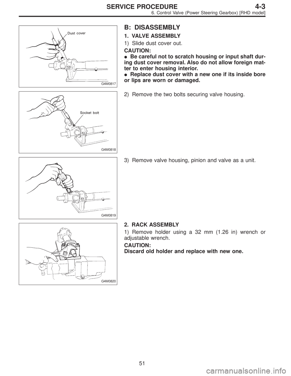
G4M0817
B: DISASSEMBLY
1. VALVE ASSEMBLY
1) Slide dust cover out.
CAUTION:
�Be careful not to scratch housing or input shaft dur-
ing dust cover removal. Also do not allow foreign mat-
ter to enter housing interior.
�Replace dust cover with a new one if its inside bore
or lips are worn or damaged.
G4M0818
2) Remove the two bolts securing valve housing.
G4M0819
3) Remove valve housing, pinion and valve as a unit.
G4M0820
2. RACK ASSEMBLY
1) Remove holder using a 32 mm (1.26 in) wrench or
adjustable wrench.
CAUTION:
Discard old holder and replace with new one.
51
4-3SERVICE PROCEDURE
6. Control Valve (Power Steering Gearbox) [RHD model]
Page 1162 of 2890
 Apply a coat of specified steering grease to ST surface,
and install ST onto end of input shaft. Insert pinion and
valve until“A”of oil seal contacts“B”of valve housing. The
ST is u")
G4M0841
5) Apply a coat of specified steering grease to ST surface,
and install ST onto end of input shaft. Insert pinion and
valve until“A”of oil seal contacts“B”of valve housing. The
ST is used to prevent scratching Y-packing.
ST 34099FA020 GUIDE
G4M0842
6) While supporting pinion and valve, push end of pinion
until bearing contacts brazed end of valve housing.
CAUTION:
Do not allow spacer to extend beyond brazed end.
Otherwise, pinion cannot be inserted properly.
G4M0843
7) Apply a coat of grease to sealing lips of dust cover, and
insert dust cover until it contacts staged portion of input
shaft.
8) Adjust sealing lip-to-housing end clearance to 0 to 0.5
mm (0 to 0.020 in). If sealing lip is too close to housing end,
steering wheel will not return smoothly; if it is too far from
housing end, dust or dirt will enter the clearance.
NOTE:
Ensure that pinion and valve is properly positioned in valve
housing before adjustment.
G4M0826
2. PINION AND VALVE ASSEMBLY
�Removal
1) Remove snap ring securing valve sleeve to pinion and
valve, and remove valve sleeve.
CAUTION:
Be careful not to scratch pinion and valve when remov-
ing snap ring.
G4M0827
2) Remove oil seal and spacer.
3) Using a long rod, remove seal ring and O-ring from
pinion.
CAUTION:
Be careful not to scratch outer surface and seal ring
groove of input shaft. If scratched, sealing effect will
be lost, resulting in a malfunctioning valve.
55
4-3SERVICE PROCEDURE
6. Control Valve (Power Steering Gearbox) [RHD model]
Page 1163 of 2890
 Wash and clean pinion & valve and valve housing.
2) Attach ST to pinion, and apply grease to outer perimeter
of the cover and mating surface of oil seal.
ST 926270000 COVER
G4")
G4M0828
�Installation
1) Wash and clean pinion & valve and valve housing.
2) Attach ST to pinion, and apply grease to outer perimeter
of the cover and mating surface of oil seal.
ST 926270000 COVER
G4M0829
3) Apply a coat of grease to spacer and sealing lips of oil
seal, and install spacer and oil seal.
CAUTION:
�Face chamfered side of spacer toward oil seal.
�Face oil seal in correct direction.
G4M0830
4) Install ST to input shaft, and apply a coat of grease to
the cover surface. Install O-ring and seal ring.
CAUTION:
Do not expand O-ring and seal ring more than neces-
sary.
ST 926450000 COVER
G4M0831
5) Apply a coat of grease to inner wall of ST, and secure
seal ring assembled in step 4) as shown. Leave seal ring
unattended for approximately 10 minutes until it settles
down.
ST 926280000 FORMER
G4M0832
6) While aligning valve sleeve pin with groove on pinion,
secure with snap ring.
CAUTION:
�Be careful not to damage inner wall of valve sleeve
and contact surface of pinion.
�Before assembling valve sleeve and pinion, clean in
kerosene and dry with compressed air.
56
4-3SERVICE PROCEDURE
6. Control Valve (Power Steering Gearbox) [RHD model]
Page 1178 of 2890

A: REMOVAL
1) Remove ground cable from battery.
2) Drain the working fluid about 0.35�(0.4 US qt, 0.3 Imp
qt) from oil tank.
3) Remove pulley belt cover bra")
B4M0558
9. Oil Pump (Power Steering System)
A: REMOVAL
1) Remove ground cable from battery.
2) Drain the working fluid about 0.35�(0.4 US qt, 0.3 Imp
qt) from oil tank.
3) Remove pulley belt cover bracket.
B4M0559A
4) Loosen oil pump pulley nut, then remove bolts which
secure alternator.
5) Loosen pulley belt(s).
6) Remove the nut and detach oil pump pulley.
B4M0556A
7) Remove bolt A. Disconnect pipe C from oil pump. Dis-
connect pipe D from oil tank.
CAUTION:
�Do not allow fluid from the hose end to come into
contact with pulley belt.
�To prevent foreign matter from entering the hose
and pipe, cover the open ends of them with a clean
cloth.
�Except when only oil tank needs to be inspected,
detach oil tank and oil pump as a unit. Then separate
one from the other on a work bench to prevent oil from
spilling on any part of the engine.
B4M0560
8) Remove three bolts from the front side of oil pump and
detach the pump.
9) Remove three bolts from the lower side of bracket and
detach the bracket.
CAUTION:
The bracket does not need to be removed unless it is
damaged.
71
4-3SERVICE PROCEDURE
9. Oil Pump (Power Steering System)
Page 1181 of 2890
C: DISASSEMBLY
B4M0142A
�1Pulley
�
2Snap ring
�
3Bearing
�
4Oil seal
�
5Shaft
�
6Connector
�
7O-ring
�
8Spool valve�
9Spring
�
10Front casing
�
11Rear cover
�
12Knock pin
�
13Seal washer
�
14Cam ring
�
15Vane
�
16Rotor�
17Side plate
Tightening torque: N⋅m (kg-m, ft-lb)
T1: 16±2 (1.6±0.2, 11.6±1.4)
T2: 61±7 (6.2±0.7, 45.0±5.2)
T3: 74±5 (7.5±0.5, 54.2±3.6)
B4M0561A
1) Oil pump body
(1) Place oil pump in a vise, and remove two bolts
which secure tank.
CAUTION:
Do not place oil pump directly in vise; use soft pads
and hold oil pump lightly to protect it.
74
4-3SERVICE PROCEDURE
9. Oil Pump (Power Steering System)
Page 1182 of 2890
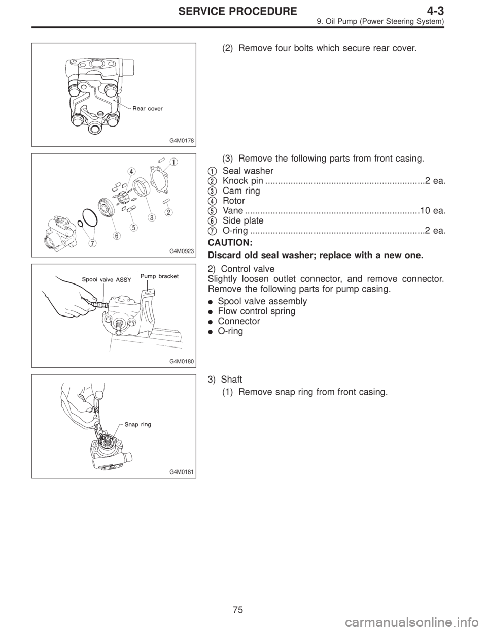
G4M0178
(2) Remove four bolts which secure rear cover.
G4M0923
(3) Remove the following parts from front casing.
�
1Seal washer
�
2Knock pin ...............................................................2 ea.
�
3Cam ring
�
4Rotor
�
5Vane .....................................................................10 ea.
�
6Side plate
�
7O-ring .....................................................................2 ea.
CAUTION:
Discard old seal washer; replace with a new one.
G4M0180
2) Control valve
Slightly loosen outlet connector, and remove connector.
Remove the following parts for pump casing.
�Spool valve assembly
�Flow control spring
�Connector
�O-ring
G4M0181
3) Shaft
(1) Remove snap ring from front casing.
75
4-3SERVICE PROCEDURE
9. Oil Pump (Power Steering System)
 Apply genuine grease to pinion gear and bearing of
valve assembly.
B4M0135
2) Install packing on valve assembly. Insert valve assem-
bly into place while facing rack teeth")