Page 1274 of 2890
14. ABS Sensor
A: REMOVAL
1. FRONT ABS SENSOR
1) Disconnect front ABS sensor connector located in
engine compartment.
B4M0079A
2) Remove bolts which secure sensor harness to strut.
G4M0451
3) Remove bolts which secure sensor harness to body.
G4M0443
4) Remove bolts which secure front ABS sensor to
housing, and remove front ABS sensor.
CAUTION:
�Be careful not to damage pole piece located at tip of
the sensor and teeth faces during removal.
�Do not pull sensor harness during removal.
5) Remove front disc brake caliper and disc rotor from
housing after removing front tire.
6) Remove front drive shaft and housing and hub assem-
bly.
67
4-4SERVICE PROCEDURE
14. ABS Sensor
Page 1280 of 2890
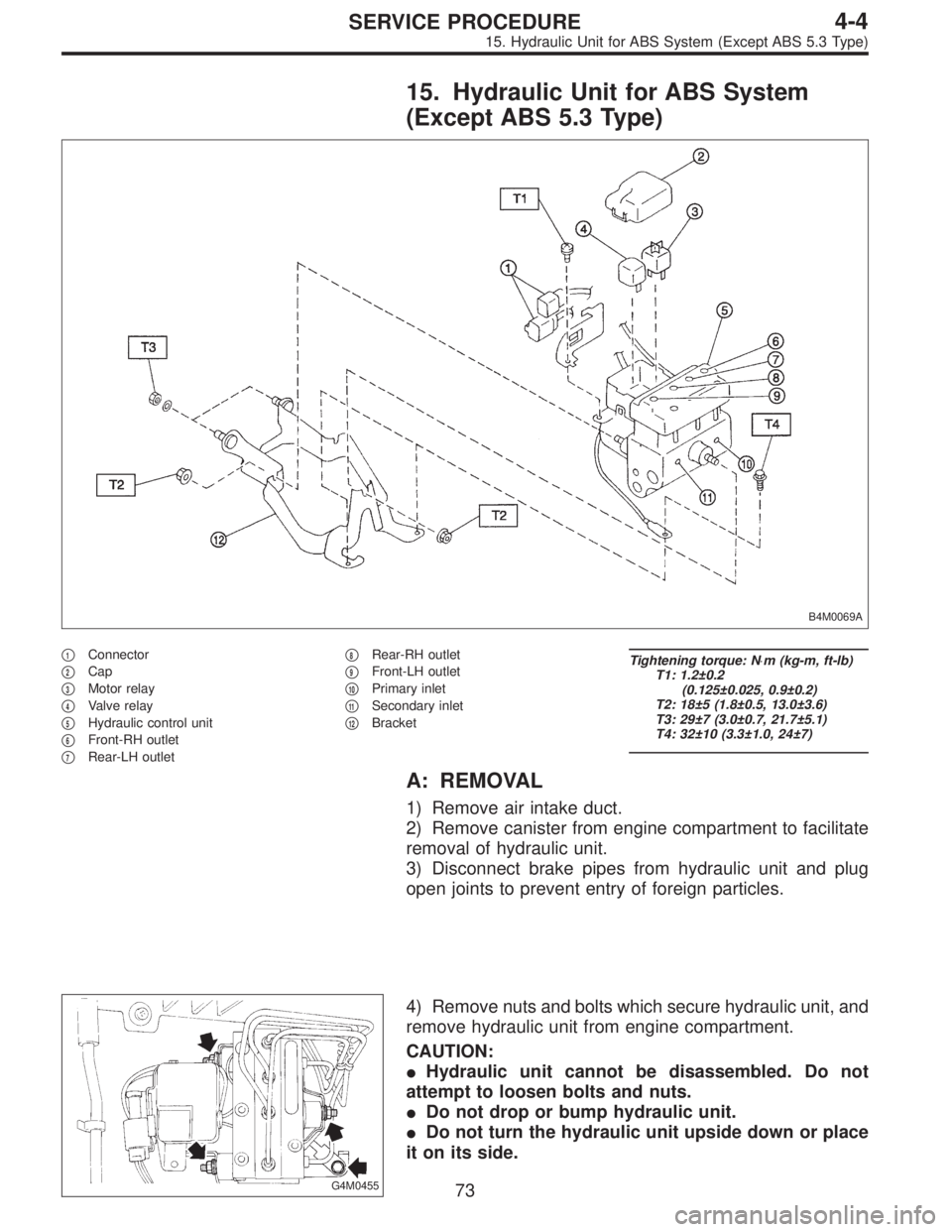
15. Hydraulic Unit for ABS System
(Except ABS 5.3 Type)
B4M0069A
�1Connector
�
2Cap
�
3Motor relay
�
4Valve relay
�
5Hydraulic control unit
�
6Front-RH outlet
�
7Rear-LH outlet�
8Rear-RH outlet
�
9Front-LH outlet
�
10Primary inlet
�
11Secondary inlet
�
12Bracket
Tightening torque: N⋅m (kg-m, ft-lb)
T1: 1.2±0.2
(0.125±0.025, 0.9±0.2)
T2: 18±5 (1.8±0.5, 13.0±3.6)
T3: 29±7 (3.0±0.7, 21.7±5.1)
T4: 32±10 (3.3±1.0, 24±7)
A: REMOVAL
1) Remove air intake duct.
2) Remove canister from engine compartment to facilitate
removal of hydraulic unit.
3) Disconnect brake pipes from hydraulic unit and plug
open joints to prevent entry of foreign particles.
G4M0455
4) Remove nuts and bolts which secure hydraulic unit, and
remove hydraulic unit from engine compartment.
CAUTION:
�Hydraulic unit cannot be disassembled. Do not
attempt to loosen bolts and nuts.
�Do not drop or bump hydraulic unit.
�Do not turn the hydraulic unit upside down or place
it on its side.
73
4-4SERVICE PROCEDURE
15. Hydraulic Unit for ABS System (Except ABS 5.3 Type)
Page 1287 of 2890
G4M0455
D: INSTALLATION
1) Install relay box cover on hydraulic unit.
2) Install hydraulic unit to bracket.
Tightening torque:
18±5 N⋅m (1.8±0.5 kg-m, 13.0±3.6 ft-lb)
3) Tighten bracket and motor ground lead as a unit.
Tightening torque:
32±10 N⋅m (3.3±1.0 kg-m, 24±7 ft-lb)
4) Connect brake pipes to their correct hydraulic unit con-
nections.
Tightening torque:
15
+3
�2N⋅m (1.5+0.3
�0.2kg-m, 10.8+2.2
�1.4ft-lb)
16. ABS Control Module (Except ABS
5.3 Type)
A: REMOVAL
1) Remove floor mat located under lower right side of front
seat.
G4M0468
2) Remove screw which secure ABS control module from
the body.
G4M0469
3) Disconnect connector from ABS control module.
80
4-4SERVICE PROCEDURE
15. Hydraulic Unit for ABS System (Except ABS 5.3 Type) - 16. ABS Control Module (Except ABS 5.3 Type)
Page 1288 of 2890
G4M0455
D: INSTALLATION
1) Install relay box cover on hydraulic unit.
2) Install hydraulic unit to bracket.
Tightening torque:
18±5 N⋅m (1.8±0.5 kg-m, 13.0±3.6 ft-lb)
3) Tighten bracket and motor ground lead as a unit.
Tightening torque:
32±10 N⋅m (3.3±1.0 kg-m, 24±7 ft-lb)
4) Connect brake pipes to their correct hydraulic unit con-
nections.
Tightening torque:
15
+3
�2N⋅m (1.5+0.3
�0.2kg-m, 10.8+2.2
�1.4ft-lb)
16. ABS Control Module (Except ABS
5.3 Type)
A: REMOVAL
1) Remove floor mat located under lower right side of front
seat.
G4M0468
2) Remove screw which secure ABS control module from
the body.
G4M0469
3) Disconnect connector from ABS control module.
80
4-4SERVICE PROCEDURE
15. Hydraulic Unit for ABS System (Except ABS 5.3 Type) - 16. ABS Control Module (Except ABS 5.3 Type)
Page 1289 of 2890
B: INSPECTION
Check that connector is connected correctly and that con-
nector terminal sliding resistance is correct.
G4M0469
C: INSTALLATION
1) Connect connector to ABS control module.
2) Install ABS control module on the body.
G4M0470
17. G Sensor for ABS System (Except
ABS 5.3 Type)
A: REMOVAL AND INSTALLATION
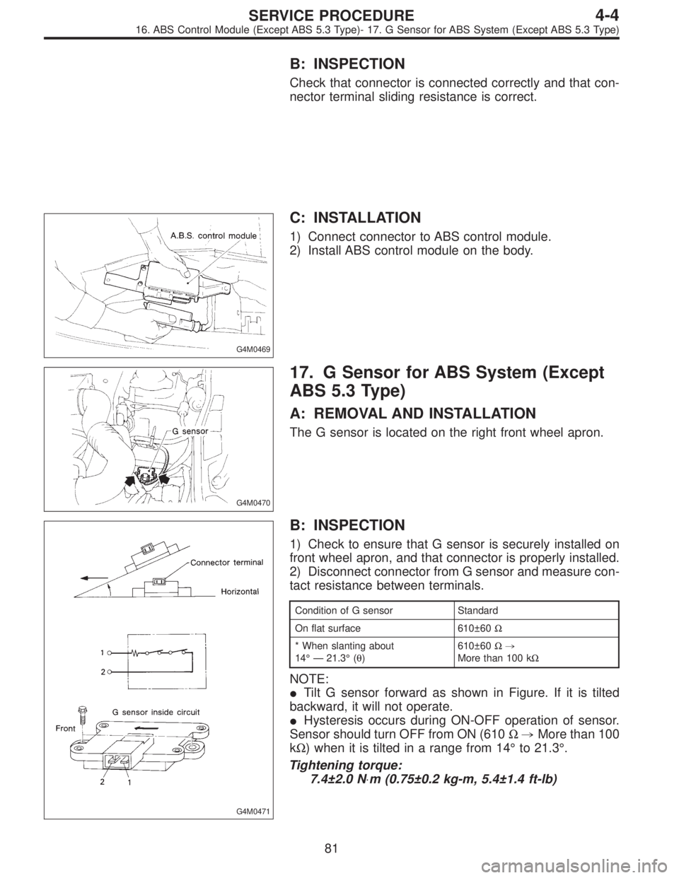
The G sensor is located on the right front wheel apron.
G4M0471
B: INSPECTION
1) Check to ensure that G sensor is securely installed on
front wheel apron, and that connector is properly installed.
2) Disconnect connector from G sensor and measure con-
tact resistance between terminals.
Condition of G sensor Standard
On flat surface 610±60Ω
* When slanting about
14°—21.3°(θ)610±60Ω,
More than 100 kΩ
NOTE:
�Tilt G sensor forward as shown in Figure. If it is tilted
backward, it will not operate.
�Hysteresis occurs during ON-OFF operation of sensor.
Sensor should turn OFF from ON (610Ω,More than 100
kΩ) when it is tilted in a range from 14°to 21.3°.
Tightening torque:
7.4±2.0 N⋅m (0.75±0.2 kg-m, 5.4±1.4 ft-lb)
81
4-4SERVICE PROCEDURE
16. ABS Control Module (Except ABS 5.3 Type)- 17. G Sensor for ABS System (Except ABS 5.3 Type)
Page 1290 of 2890
B: INSPECTION
Check that connector is connected correctly and that con-
nector terminal sliding resistance is correct.
G4M0469
C: INSTALLATION
1) Connect connector to ABS control module.
2) Install ABS control module on the body.
G4M0470
17. G Sensor for ABS System (Except
ABS 5.3 Type)
A: REMOVAL AND INSTALLATION
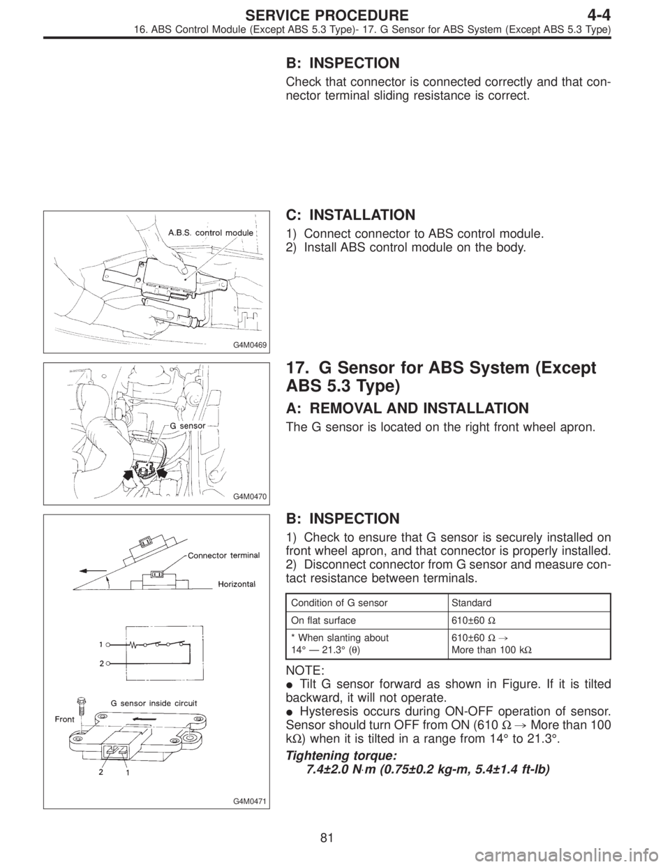
The G sensor is located on the right front wheel apron.
G4M0471
B: INSPECTION
1) Check to ensure that G sensor is securely installed on
front wheel apron, and that connector is properly installed.
2) Disconnect connector from G sensor and measure con-
tact resistance between terminals.
Condition of G sensor Standard
On flat surface 610±60Ω
* When slanting about
14°—21.3°(θ)610±60Ω,
More than 100 kΩ
NOTE:
�Tilt G sensor forward as shown in Figure. If it is tilted
backward, it will not operate.
�Hysteresis occurs during ON-OFF operation of sensor.
Sensor should turn OFF from ON (610Ω,More than 100
kΩ) when it is tilted in a range from 14°to 21.3°.
Tightening torque:
7.4±2.0 N⋅m (0.75±0.2 kg-m, 5.4±1.4 ft-lb)
81
4-4SERVICE PROCEDURE
16. ABS Control Module (Except ABS 5.3 Type)- 17. G Sensor for ABS System (Except ABS 5.3 Type)
Page 1296 of 2890
(2) Slowly depress the brake pedal and keep it
depressed. Then, open the air bleeder to discharge air
together with the fluid.
Release air bleeder for 1 to 2 seconds.
Next, with the bleeder closed, slowly release the brake
pedal.
Repeat these steps until there are no more air bubbles
in the vinyl tube.
Allow 3 to 4 seconds between two brake pedal opera-
tions.
CAUTION:
Cover bleeder with waste cloth, when loosening it, to
prevent brake fluid from being splashed over sur-
rounding parts.
NOTE:
Brake pedal operating must be very slow.
4) Bleed air from suction pipe through front RH caliper.
(1) Open the air bleeder.
(2) Keep pressing TCS OFF switch for 20 seconds or
more.
NOTE:
Ensure no air comes out from air bleeder.
(3) Close the air bleeder.
5) Bleed air through front LH caliper by operating brake
pedal. This is the same procedure as step 3).
6) Bleed air from suction pipe through front LH caliper.
This is the same procedure as step 4).
7) Bleed air through front RH and LH calipers by operat-
ing brake pedal. This is the same procedure as step 3).
Repeat steps 3) to 7) until air does no longer comes out.
8) Tighten air bleeders securely when bubbles are visible.
Air bleeder tightening torque:
8±1 N⋅m (0.8±0.1 kg-m, 5.8±0.7 ft-lb)
9) Bleed air through rear LH and RH caliper by operating
brake pedal. This is the same procedure as step 3).
10) Tighten air bleeders securely when bubbles are vis-
ible.
Air bleeder tightening torque:
8±1 N⋅m (0.8±0.1 kg-m, 5.8±0.7 ft-lb)
87
4-4SERVICE PROCEDURE
19. Air Bleeding (With TCS model)
Page 1303 of 2890
B4M0628
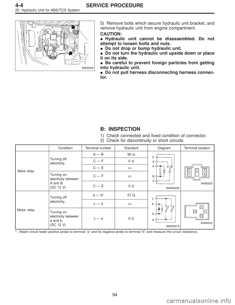
5) Remove bolts which secure hydraulic unit bracket, and
remove hydraulic unit from engine compartment.
CAUTION:
�Hydraulic unit cannot be disassembled. Do not
attempt to loosen bolts and nuts.
�Do not drop or bump hydraulic unit.
�Do not turn the hydraulic unit upside down or place
it on its side.
�Be careful to prevent foreign particles from getting
into hydraulic unit.
�Do not pull harness disconnecting harness connec-
tor.
B: INSPECTION
1) Check connected and fixed condition of connector.
2) Check for discontinuity or short circuits.
Condition Terminal number Standard Diagram Terminal location
Valve relayTurning off
electricity.A—B90Ω
B4M0629A
B4M0630
C—F0Ω
C—E
Turning on
electricity between
A and B.
(DC 12 V)C—F
C—E0Ω
Motor relayTurning off
electricity.a—b* 57Ω
B4M0631AB4M0632
c—d
Turning on
electricity between
a and b.
(DC 12 V)c—d0Ω
*: Attach circuit tester positive probe to terminal“a”and its negative probe to terminal“b”and measure the circuit resistance.
94
4-4SERVICE PROCEDURE
20. Hydraulic Unit for ABS/TCS System