Page 1517 of 2890
G5M0392
4. CHECKER
1) Remove trim panel.
2) Remove sealing cover.
3) Apply a cloth to door and body to prevent damaging
them, and remove checker pin by driving it upward.
CAUTION:
Be careful not to damage door and body.
4) Completely close door glass.
5) Loosen two nuts securing checker, and take out
checker through access hole in underside.
Installation should be made in the reverse order of
removal.
Tightening torque:
7.4±2.0 N⋅m (0.75±0.2 kg-m, 5.4±1.4 ft-lb)
5. DOOR GLASS
1) Remove trim panel.
2) Remove sealing cover.
3) Disconnect door mirror connector and then remove
gusset�
1.
4) Remove inner remote.
B5M0063A
5) Remove inner stabilizer�1.
B5M0064A
6) Remove nut and then separate glass holder�1from
guide channel A�
2.
NOTE:
When removing nut, move door window lower glass con-
necting section to service hole of door panel.
7) Remove window glass upward.
CAUTION:
After removing window glass, do not move regulator.
15
5-2SERVICE PROCEDURE
2. Door
Page 1519 of 2890
7. DOOR LATCH
1) Remove trim panel.
2) Remove inner remote assembly.
3) Remove sealing cover around latch service hole.
to 5-2 [W2A3].>
4) Completely close door glass.
B5M0067
5) Remove latch and actuator assembly.
(1) Turn rod holder to disconnect joint between key
lock and rod.
(2) Turn rod holder to disconnect joint between outer
handle and rod.
(3) Turn rod holder to disconnect joint between crank
and rod.
G5M0396
6) Loosen screws securing both latch and actuator, then
remove latch and actuator assembly through service hole
in bottom.
Tightening torque (screw):
6.4±2.0 N⋅m (0.65±0.2 kg-m, 4.7±1.4 ft-lb)
7) Installation is in the reverse order of removal.
Some special items will be described below.
8) Check operation of each part.
9) Check each sliding part for proper lubrication.
CAUTION:
After installation, be sure lock mechanism operates
normally.
17
5-2SERVICE PROCEDURE
2. Door
Page 1520 of 2890
B5M0068
8. OUTER HANDLE
1) Remove trim panel.
2) Remove sealing cover.
3) Detach door latch rod from outer handle and key lock.
4) Loosen nut securing outer handle and then remove
outer handle from outside.
CAUTION:
Be careful not to damage door.
Installation is in the reverse order of removal.
Tightening torque:
7.4±2.0 N⋅m (0.75±0.2 kg-m, 5.4±1.4 ft-lb)
B5M0069A
9. KEY LOCK
1) Remove trim panel.
2) Remove sealing cover.
3) Completely close door glass.
4) Remove outer handle.
5) Loosen spring�
1securing key lock.
6) Remove key lock from outer handle.
Installation is in the reverse order of removal.
NOTE:
Install so that key slot in key lock comes to center of hole
in outer handle.
B5M0070A
10. GUSSET
NOTE:
Be sure window is all the way down.
1) Remove trim panel.
2) Remove door rearview mirror.
3) Remove sealing cover.
4) Remove bolts and nuts which secure gusset.
5) Lift out gusset�
1.
To install, reverse the above removal procedures.
18
5-2SERVICE PROCEDURE
2. Door
Page 1521 of 2890
B: ADJUSTMENT
1. DOOR ASSY
1) Using ST, loosen bolts securing upper and lower hinges
to body, and adjust fore-and-aft and vertical alignment of
door.
ST 925610000 DOOR HINGE WRENCH
B5M0071A
2) Loosen mounting screws approximately one rotation.
Adjust striker�
1position by lightly tapping with hammer. (To
adjust, utilize the shape of striker nut plate�
2support.)
CAUTION:
�Use cloth to prevent damaging body or other parts.
�Do not directly tap striker plastic portion.
�Do not apply impact on spot-welded striker nut
plate.
Hinge tightening torque (body side):
29±5 N⋅m (3.0±0.5 kg-m, 21.7±3.6 ft-lb)
Striker tightening torque:
14±4 N⋅m (1.4±0.4 kg-m, 10.1±2.9 ft-lb)
19
5-2SERVICE PROCEDURE
2. Door
Page 1524 of 2890
3) Lower door glass 10 to 15 mm (0.39 to 0.59 in) from
fully closed position. While applying outward pressure
(load) to upper edge of glass above midpoint of two outer
stabilizers, press inner stabilizer until it just touches the
glass, then secure it.
Load: F
Front door glass 39 N (4 kg, 9 lb)
Rear door glass 34.3 N (3.5 kg, 7.7 lb)
G5M0498
�Remedy for unequal dimensions, between upper,
lower and center pillar sides
1) Close front door and raise door glass.
2) Make sure of unequal dimensions.
B5M0073A
3) If glass tilts to far rearward, loosen adjusting nut�Cand
adjust glass to be parallel with center pillar, then after
adjustment, tighten adjusting nut�
C.
B5M0074A
�Remedy for improper glass to center pillar clearance
1) Close front door and raise door glass.
2) Make sure of improper clearance.
22
5-2SERVICE PROCEDURE
2. Door
Page 1526 of 2890
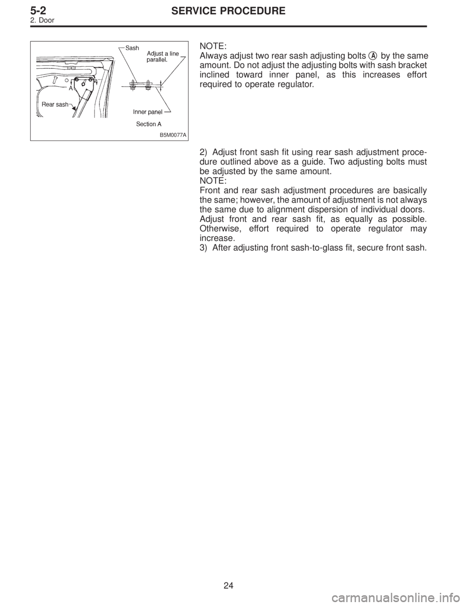
B5M0077A
NOTE:
Always adjust two rear sash adjusting bolts�
Aby the same
amount. Do not adjust the adjusting bolts with sash bracket
inclined toward inner panel, as this increases effort
required to operate regulator.
2) Adjust front sash fit using rear sash adjustment proce-
dure outlined above as a guide. Two adjusting bolts must
be adjusted by the same amount.
NOTE:
Front and rear sash adjustment procedures are basically
the same; however, the amount of adjustment is not always
the same due to alignment dispersion of individual doors.
Adjust front and rear sash fit, as equally as possible.
Otherwise, effort required to operate regulator may
increase.
3) After adjusting front sash-to-glass fit, secure front sash.
24
5-2SERVICE PROCEDURE
2. Door
Page 1534 of 2890
 Remove glass.
(1) Put protective tape on body to prevent damage.
(2) Using drill or putty knife, make through-hole (one
place) in adhesive agent.
(3) Pass piano wire through the hole from i")
G5M0494
3) Remove glass.
(1) Put protective tape on body to prevent damage.
(2) Using drill or putty knife, make through-hole (one
place) in adhesive agent.
(3) Pass piano wire through the hole from inside the
compartment, and connect both ends of wire securely
to wooden blocks.
(4) Cut adhesive layer with the wire by pulling it back
and forth.
CAUTION:
When making through-hole into adhesive layer and
cutting the adhesive, be careful not to damage interior
and exterior parts.
B: INSTALLATION
1) After cutting layer of adhesive, remove dam rubber
remaining on body.
G5M0553
2) Finishing adhesion surface on body side
Using a cutter knife etc., cut layer of adhesive sticking
firmly to body, and finish it to a smooth surface of about 2
mm (0.08 in) in thickness.
CAUTION:
Take extra care not to cause damage to body paint.
3) Cleaning body surface
(1) Thoroughly remove chips, dirt and dust from body
surface.
(2) Clean body wall surface and upper surface of layer
of adhesive with a solvent such as alcohol or white
gasoline.
32
5-2SERVICE PROCEDURE
5. Windshield
Page 1551 of 2890
 While operating knob (located on top of backrest), lift
headrest out with hand placed between backrest and head-
rest.
2) Pull reclining lever back to fold backrest")
G5M0342
1. Front Seat
A: REMOVAL
1) While operating knob (located on top of backrest), lift
headrest out with hand placed between backrest and head-
rest.
2) Pull reclining lever back to fold backrest all the way for-
ward. While pulling slide adjuster lever, move seat all the
way forward.
B5M0332
3) Disconnect connector under driver’s seat.
4) Remove bolt cover at rear end of slide rail.
5) Remove bolts securing seat rear.
G5M0344
6) While pulling slide adjuster lever, slide seat all the way
back.
7) Remove bolts securing front of seat.
8) Remove front seat from vehicle, then install headrest.
CAUTION:
Be careful not to scratch seat when removing it from
vehicle.
G5M0342
B: INSTALLATION
1) While operating knob (located on top of backrest), lift
headrest out with hand placed between backrest and head-
rest.
2) Pull reclining lever back to fold backrest all the way for-
ward. Pull slide adjuster lever and move lower slide rail all
the way backward.
8
5-3SERVICE PROCEDURE
1. Front Seat
![SUBARU LEGACY 1996 Service Repair Manual G5M0392
4. CHECKER
1) Remove trim panel. <Ref. to 5-2 [W2A2].>
2) Remove sealing cover. <Ref. to 5-2 [W2A3].>
3) Apply a cloth to door and body to prevent damaging
them, and remove checker pin by driv](/manual-img/17/57433/w960_57433-1516.png "SUBARU LEGACY 1996 Service Repair Manual G5M0392
4. CHECKER
1) Remove trim panel. <Ref. to 5-2 [W2A2].>
2) Remove sealing cover. <Ref. to 5-2 [W2A3].>
3) Apply a cloth to door and body to prevent damaging
them, and remove checker pin by driv")
![SUBARU LEGACY 1996 Service Repair Manual 7. DOOR LATCH
1) Remove trim panel. <Ref. to 5-2 [W2A2].>
2) Remove inner remote assembly. <Ref. to 5-2 [W2A6].>
3) Remove sealing cover around latch service hole. <Ref.
to 5-2 [W2A3].>
4) Completely](/manual-img/17/57433/w960_57433-1518.png "SUBARU LEGACY 1996 Service Repair Manual 7. DOOR LATCH
1) Remove trim panel. <Ref. to 5-2 [W2A2].>
2) Remove inner remote assembly. <Ref. to 5-2 [W2A6].>
3) Remove sealing cover around latch service hole. <Ref.
to 5-2 [W2A3].>
4) Completely")
![SUBARU LEGACY 1996 Service Repair Manual B5M0068
8. OUTER HANDLE
1) Remove trim panel. <Ref. to 5-2 [W2A2].>
2) Remove sealing cover. <Ref. to 5-2 [W2A3].>
3) Detach door latch rod from outer handle and key lock.
4) Loosen nut securing outer](/manual-img/17/57433/w960_57433-1519.png "SUBARU LEGACY 1996 Service Repair Manual B5M0068
8. OUTER HANDLE
1) Remove trim panel. <Ref. to 5-2 [W2A2].>
2) Remove sealing cover. <Ref. to 5-2 [W2A3].>
3) Detach door latch rod from outer handle and key lock.
4) Loosen nut securing outer")
 Using ST, loosen bolts securing upper and lower hinges
to body, and adjust fore-and-aft and vertical alignment of
door.
ST 925610000 DOOR HINGE WRENCH
B5M0071A
2) Loosen")
 Lower door glass 10 to 15 mm (0.39 to 0.59 in) from
fully closed position. While applying outward pressure
(load) to upper edge of glass above midpoint of two outer
stabilizers, press inner stabili")