Page 1645 of 2890
B6M0555A
3) Remove #2 spark plug cord by pulling boot, not cord
itself.
4) For subsequent procedures, refer to the procedure for
#1 spark plug.
CAUTION:
When removing spark plug, cover the ATF cooling
pipes with a rag to prevent damage.
G6M0095
3. #3 SPARK PLUG
1) Disconnect battery ground cable.
B6M0557A
2) Disconnect mass air flow sensor connector.
3) Remove four clips securing air cleaner upper cover.
B6M0558
4) Loosen the clamp screw and separate air cleaner upper
cover from air intake duct.
B6M0565A
5) Remove air cleaner element and air cleaner case.
31
6-1SERVICE PROCEDURE
3. Spark Plug
Page 1657 of 2890

1. Precaution
�Before disassembling or reassembling parts, always
disconnect battery ground cable. When repairing
radio, control modules, etc. which are provided with
memory functions, record memory contents before
disconnecting battery ground cable. Otherwise, these
contents are cancelled upon disconnection.
�Reassemble parts in reverse order of disassembly
procedure unless otherwise indicated.
�Adjust parts to specifications contained in this
manual if so designated.
�Connect connectors and hoses securely during
reassembly.
�After reassembly, ensure functional parts operate
smoothly.
CAUTION:
�Airbag system wiring harness is routed near the
electrical parts and switch.
�All Airbag system wiring harness and connectors
are colored yellow. Do not use electrical test equip-
ment on these circuit.
�Be careful not to damage Airbag system wiring har-
ness when servicing the ignition key cylinder.
G6M0102
2. Battery
A: REMOVAL AND INSTALLATION
1. BATTERY
1) Disconnect the positive (+) terminal after disconnecting
the negative (�) terminal of battery.
2) Remove flange nuts from battery rods and take off bat-
tery holder.
3) Remove battery.
Tightening torque:
3.4±1.0 N⋅m (0.35±0.1 kg-m, 2.5±0.7 ft-lb)
NOTE:
�Clean battery cable terminals and apply grease to retard
the formation of corrosion.
�Connect the positive (+) terminal of battery and then the
negative (�) terminal of the battery.
4
6-2SERVICE PROCEDURE
1. Precaution - 2. Battery
Page 1658 of 2890

1. Precaution
�Before disassembling or reassembling parts, always
disconnect battery ground cable. When repairing
radio, control modules, etc. which are provided with
memory functions, record memory contents before
disconnecting battery ground cable. Otherwise, these
contents are cancelled upon disconnection.
�Reassemble parts in reverse order of disassembly
procedure unless otherwise indicated.
�Adjust parts to specifications contained in this
manual if so designated.
�Connect connectors and hoses securely during
reassembly.
�After reassembly, ensure functional parts operate
smoothly.
CAUTION:
�Airbag system wiring harness is routed near the
electrical parts and switch.
�All Airbag system wiring harness and connectors
are colored yellow. Do not use electrical test equip-
ment on these circuit.
�Be careful not to damage Airbag system wiring har-
ness when servicing the ignition key cylinder.
G6M0102
2. Battery
A: REMOVAL AND INSTALLATION
1. BATTERY
1) Disconnect the positive (+) terminal after disconnecting
the negative (�) terminal of battery.
2) Remove flange nuts from battery rods and take off bat-
tery holder.
3) Remove battery.
Tightening torque:
3.4±1.0 N⋅m (0.35±0.1 kg-m, 2.5±0.7 ft-lb)
NOTE:
�Clean battery cable terminals and apply grease to retard
the formation of corrosion.
�Connect the positive (+) terminal of battery and then the
negative (�) terminal of the battery.
4
6-2SERVICE PROCEDURE
1. Precaution - 2. Battery
Page 1663 of 2890

1) Remove instrument panel lower cover.
2) Remove lower column cover.
3) Unfasten holddown clip which secures harness, and
disconnect connector of ign")
B6M0048
B: INSPECTION
1. IGNITION SWITCH (ON-CAR)
1) Remove instrument panel lower cover.
2) Remove lower column cover.
3) Unfasten holddown clip which secures harness, and
disconnect connector of ignition switch from body harness.
4) Turn ignition key to each position and check continuity
between terminals of ignition switch connector.
Terminal
Positiona-1 a-2 a-5 a-4
LOCK
ACC��
ON���
START���
B6M0335A
4. Headlight
A: ADJUSTMENT
1. HEADLIGHT AIMING
1) Adjust the headlight aiming by turning the adjusting
screws.
CAUTION:
Before checking the headlight aiming, be sure of the
following:
�Turn off the light before adjusting headlight aiming.
If the light is necessary to check aiming, do not turn on
for more than two minutes.
�The area around the headlight has not sustained any
accident, damage or other type of deformation.
�Vehicle is parked on level ground.
�The inflation pressure of tires is correct.
�Vehicle’s gas tank is fully charged.
�Bounce the vehicle several times to normalize the
suspension.
�Make certain that someone is seated in the driver’s
seat.
NOTE:
Adjust vertical aim first, then horizontal aim.
8
6-2SERVICE PROCEDURE
3. Ignition Switch - 4. Headlight
Page 1664 of 2890

1) Remove instrument panel lower cover.
2) Remove lower column cover.
3) Unfasten holddown clip which secures harness, and
disconnect connector of ign")
B6M0048
B: INSPECTION
1. IGNITION SWITCH (ON-CAR)
1) Remove instrument panel lower cover.
2) Remove lower column cover.
3) Unfasten holddown clip which secures harness, and
disconnect connector of ignition switch from body harness.
4) Turn ignition key to each position and check continuity
between terminals of ignition switch connector.
Terminal
Positiona-1 a-2 a-5 a-4
LOCK
ACC��
ON���
START���
B6M0335A
4. Headlight
A: ADJUSTMENT
1. HEADLIGHT AIMING
1) Adjust the headlight aiming by turning the adjusting
screws.
CAUTION:
Before checking the headlight aiming, be sure of the
following:
�Turn off the light before adjusting headlight aiming.
If the light is necessary to check aiming, do not turn on
for more than two minutes.
�The area around the headlight has not sustained any
accident, damage or other type of deformation.
�Vehicle is parked on level ground.
�The inflation pressure of tires is correct.
�Vehicle’s gas tank is fully charged.
�Bounce the vehicle several times to normalize the
suspension.
�Make certain that someone is seated in the driver’s
seat.
NOTE:
Adjust vertical aim first, then horizontal aim.
8
6-2SERVICE PROCEDURE
3. Ignition Switch - 4. Headlight
Page 1666 of 2890
2. HEADLIGHT
1) Remove front grille and disconnect connectors from
headlight.
B6M0338
2) Remove bolts which secure headlight and remove
headlight.
Tightening torque:
6.4±0.5 N⋅m (0.65±0.05 kg-m, 4.7±0.4 ft-lb)
NOTE:
When installing the headlight, securely fit clip into locating.
B6M0339
B6M0236
3. COMBINATION SWITCH (WITHOUT AIRBAG
MODEL)
Refer to 5-5 [W7A0] as for removal of combination
switch on airbag equipped model.
1) Remove steering wheel.
2) Remove screws which secure upper column cover to
lower column cover.
3) Remove screws which secure knee protector and
remove knee protector.
CAUTION:
When installing knee protector, ensure that harness is
not caught by adjacent parts.
4) Disconnect connector from body harness and undo
holddown band.
10
6-2SERVICE PROCEDURE
4. Headlight
Page 1667 of 2890
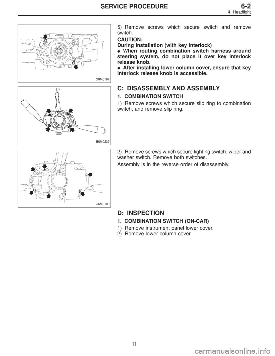
G6M0107
5) Remove screws which secure switch and remove
switch.
CAUTION:
During installation (with key interlock)
�When routing combination switch harness around
steering system, do not place it over key interlock
release knob.
�After installing lower column cover, ensure that key
interlock release knob is accessible.
B6M0237
C: DISASSEMBLY AND ASSEMBLY
1. COMBINATION SWITCH
1) Remove screws which secure slip ring to combination
switch, and remove slip ring.
G6M0109
2) Remove screws which secure lighting switch, wiper and
washer switch. Remove both switches.
Assembly is in the reverse order of disassembly.
D: INSPECTION
1. COMBINATION SWITCH (ON-CAR)
1) Remove instrument panel lower cover.
2) Remove lower column cover.
11
6-2SERVICE PROCEDURE
4. Headlight
Page 1668 of 2890
B6M0238
3) Unfasten holddown clip which secures harness, and
disconnect connectors from body harness.
4) Move combination switch to respective positions and
check continuity between terminals as indicated in the fol-
lowing tables:
Lighting switch
Terminal
Switch positionc-1 c-2 c-3
OFF
Tail��
*��
Head���
Parking switch
Terminal
Switch positionc-10 c-11 c-9
OFF��
*XX
ON��
Dimmer and passing switch
Terminal
Switch positiona-3 a-2 a-1 a-4
Flash��
�
*���
Low beam��
*���
HI-beam��
G6M0111
2. HEADLIGHT RELAY
Check continuity between terminals as indicated in table
below, when connecting the battery to terminal No. 1 and
No. 3.
When current flows.Between terminals
No. 2 and No. 4Continuity exists.
When current does not flow.Between terminals
No. 2 and No. 4Continuity does not
exist.
Between terminals
No. 1 and No. 3Continuity exists.
12
6-2SERVICE PROCEDURE
4. Headlight
![SUBARU LEGACY 1996 Service Repair Manual B6M0555A
3) Remove #2 spark plug cord by pulling boot, not cord
itself.
4) For subsequent procedures, refer to the procedure for
#1 spark plug. <Ref. to 6-1 [W3E1].>
CAUTION:
When removing spark plug,](/manual-img/17/57433/w960_57433-1644.png "SUBARU LEGACY 1996 Service Repair Manual B6M0555A
3) Remove #2 spark plug cord by pulling boot, not cord
itself.
4) For subsequent procedures, refer to the procedure for
#1 spark plug. <Ref. to 6-1 [W3E1].>
CAUTION:
When removing spark plug,")
 Remove front grille and disconnect connectors from
headlight.
B6M0338
2) Remove bolts which secure headlight and remove
headlight.
Tightening torque:
6.4±0.5 N⋅m (0.65±0.05 kg-m, 4")
 Unfasten holddown clip which secures harness, and
disconnect connectors from body harness.
4) Move combination switch to respective positions and
check continuity between terminals as indic")