Page 1681 of 2890
B6M0107A
B: REMOVAL AND INSTALLATION
1. BLADE
Pull out blade following the arrow direction from arm while
pushing up locking clip.
G6M0118
2. WIPER ARM
1) Open engine hood.
2) Remove cap of wiper arm installation nut.
3) Remove the nut which secures wiper arm.
4) Remove wiper arm.
5) Installation is in the reverse order of removal.
NOTE:
Remove metal sludge from the wiper arm fixture before
installing it.
Tightening torque:
20±3 N⋅m (2.0±0.3 kg-m, 14.5±2.2 ft-lb)
3. WIPER MOTOR AND LINK
1) Detach weatherstrip and cowl panel.
[W10A0].>
NOTE:
Apply silicone oil or soap water to both sides of cowl net to
facilitate removal.
B6M0108
2) Disconnect connector of wiper motor.
3) Remove motor attaching bolts.
Tightening torque:
5.9±1.5 N⋅m (0.6±0.15 kg-m, 4.3±1.1 ft-lb)
23
6-2SERVICE PROCEDURE
10. Front Wiper and Washer
Page 1682 of 2890

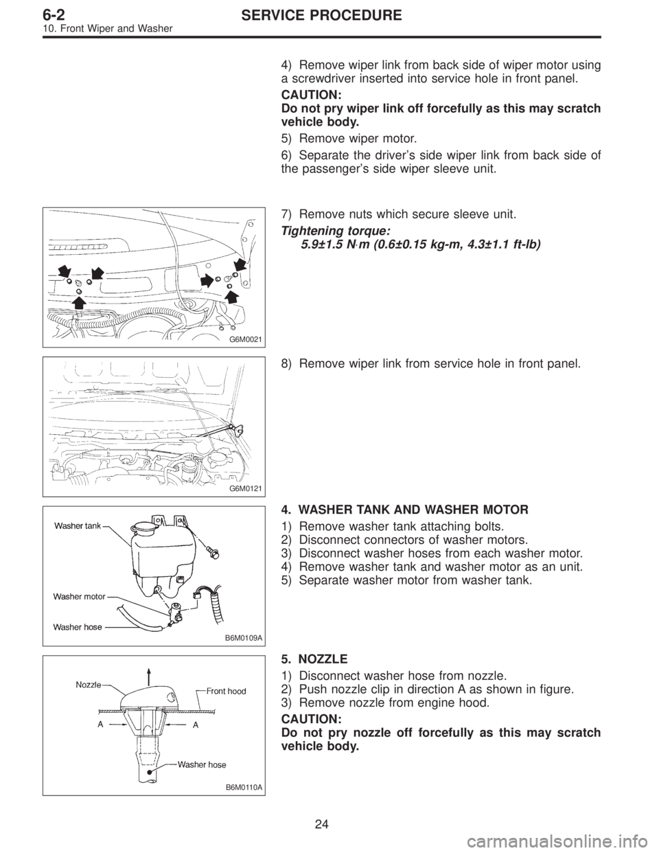
4) Remove wiper link from back side of wiper motor using
a screwdriver inserted into service hole in front panel.
CAUTION:
Do not pry wiper link off forcefully as this may scratch
vehicle body.
5) Remove wiper motor.
6) Separate the driver’s side wiper link from back side of
the passenger’s side wiper sleeve unit.
G6M0021
7) Remove nuts which secure sleeve unit.
Tightening torque:
5.9±1.5 N⋅m (0.6±0.15 kg-m, 4.3±1.1 ft-lb)
G6M0121
8) Remove wiper link from service hole in front panel.
B6M0109A
4. WASHER TANK AND WASHER MOTOR
1) Remove washer tank attaching bolts.
2) Disconnect connectors of washer motors.
3) Disconnect washer hoses from each washer motor.
4) Remove washer tank and washer motor as an unit.
5) Separate washer motor from washer tank.
B6M0110A
5. NOZZLE
1) Disconnect washer hose from nozzle.
2) Push nozzle clip in direction A as shown in figure.
3) Remove nozzle from engine hood.
CAUTION:
Do not pry nozzle off forcefully as this may scratch
vehicle body.
24
6-2SERVICE PROCEDURE
10. Front Wiper and Washer
Page 1684 of 2890
B6M0238
3) Unfasten holddown clip which secures harness, and
disconnect connectors from body harness.
4) Set wiper switch to each position and check continuity
between terminals as indicated in table below:
Wiper switch
Terminal
d-9 d-8 d-6 d-7 INT1 INT2
Switch position
OFFOFF��
*xx
MIST��
INTOFF��
��
*xx
MIST����
*xx
LOOFF��MIST��
HIOFF��MIST���
Washer switch
Terminal
d-5 d-2
Switch position
OFF
ON��
B6M0163
2. WIPER MOTOR
1) Check wiper motor operation at low speed.
Connect battery to wiper motor. Check wiper motor for
proper operation at low speed.
B6M0164
2) Check wiper motor operation at high speed.
Connect battery to wiper motor. Check wiper motor for
proper operation at high speed.
26
6-2SERVICE PROCEDURE
10. Front Wiper and Washer
Page 1687 of 2890
B6M0107A
B: REMOVAL AND INSTALLATION
1. BLADE
Pull out blade following the arrow direction, from arm while
pushing up locking clip.
B6M0112
2. WIPER ARM
1) Remove head cover.
2) Remove nut and wiper arm.
Tightening torque:
5.9±1.5 N⋅m (0.6±0.15 kg-m, 4.3±1.1 ft-lb)
B6M0113
3. WIPER MOTOR
1) Remove cap and special nut.
CAUTION:
Be careful not to strike service tool against nozzle dur-
ing removal.
Tightening torque:
7.4±1.5 N⋅m (0.75±0.15 kg-m, 5.4±1.1 ft-lb)
2) Remove rear gate trim.
3) Undo clips which secure harness, and disconnect con-
nector of wiper motor.
B6M0114
4) Separate washer hoses at joint.
5) Remove attaching screws and take out wiper motor
assembly.
CAUTION:
Be careful not to damage O-ring when removing wiper
motor assembly.
Tightening torque:
5.9±1.5 N⋅m (0.6±0.15 kg-m, 4.3±1.1 ft-lb)
28
6-2SERVICE PROCEDURE
11. Rear Wiper and Washer
Page 1689 of 2890
B6M0238
3) Unfasten holddown clip which secures harness, and
disconnect connectors from body harness.
4) Set rear wiper and washer switch to each position and
check continuity between terminals as indicated in table
below:
Terminal
Switch positiond-2 d-1 d-3
WASH��
OFF
ON��
WASH���
B6M0167
2. WIPER MOTOR
1) Operational check
Connect battery to wiper motor and check operation of
wiper motor.
B6M0168
2) Check wiper motor for proper stoppage.
After operating wiper motor, disconnect battery from wiper
motor.
B6M0169
3) Reconnect battery and ensure that wiper motor stops at
“AUTO STOP”after it has been operated.
30
6-2SERVICE PROCEDURE
11. Rear Wiper and Washer
Page 1690 of 2890

G6M0134
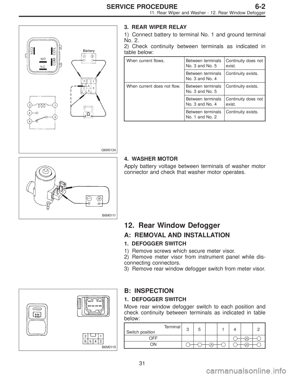
3. REAR WIPER RELAY
1) Connect battery to terminal No. 1 and ground terminal
No. 2.
2) Check continuity between terminals as indicated in
table below:
When current flows. Between terminals
No. 3 and No. 5Continuity does not
exist.
Between terminals
No. 3 and No. 4Continuity exists.
When current does not flow. Between terminals
No. 3 and No. 5Continuity exists.
Between terminals
No. 3 and No. 4Continuity does not
exist.
Between terminals
No. 1 and No. 2Continuity exists.
B6M0111
4. WASHER MOTOR
Apply battery voltage between terminals of washer motor
connector and check that washer motor operates.
12. Rear Window Defogger
A: REMOVAL AND INSTALLATION
1. DEFOGGER SWITCH
1) Remove screws which secure meter visor.
2) Remove meter visor from instrument panel while dis-
connecting connectors.
3) Remove rear window defogger switch from meter visor.
B6M0119
B: INSPECTION
1. DEFOGGER SWITCH
Move rear window defogger switch to each position and
check continuity between terminals as indicated in table
below:
Terminal
Switch position35 14 2
OFF�
�
ON�����
31
6-2SERVICE PROCEDURE
11. Rear Wiper and Washer - 12. Rear Window Defogger
Page 1691 of 2890

G6M0134
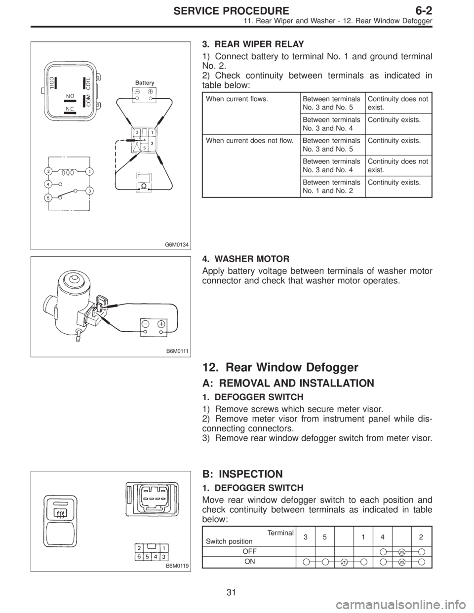
3. REAR WIPER RELAY
1) Connect battery to terminal No. 1 and ground terminal
No. 2.
2) Check continuity between terminals as indicated in
table below:
When current flows. Between terminals
No. 3 and No. 5Continuity does not
exist.
Between terminals
No. 3 and No. 4Continuity exists.
When current does not flow. Between terminals
No. 3 and No. 5Continuity exists.
Between terminals
No. 3 and No. 4Continuity does not
exist.
Between terminals
No. 1 and No. 2Continuity exists.
B6M0111
4. WASHER MOTOR
Apply battery voltage between terminals of washer motor
connector and check that washer motor operates.
12. Rear Window Defogger
A: REMOVAL AND INSTALLATION
1. DEFOGGER SWITCH
1) Remove screws which secure meter visor.
2) Remove meter visor from instrument panel while dis-
connecting connectors.
3) Remove rear window defogger switch from meter visor.
B6M0119
B: INSPECTION
1. DEFOGGER SWITCH
Move rear window defogger switch to each position and
check continuity between terminals as indicated in table
below:
Terminal
Switch position35 14 2
OFF�
�
ON�����
31
6-2SERVICE PROCEDURE
11. Rear Wiper and Washer - 12. Rear Window Defogger
Page 1693 of 2890

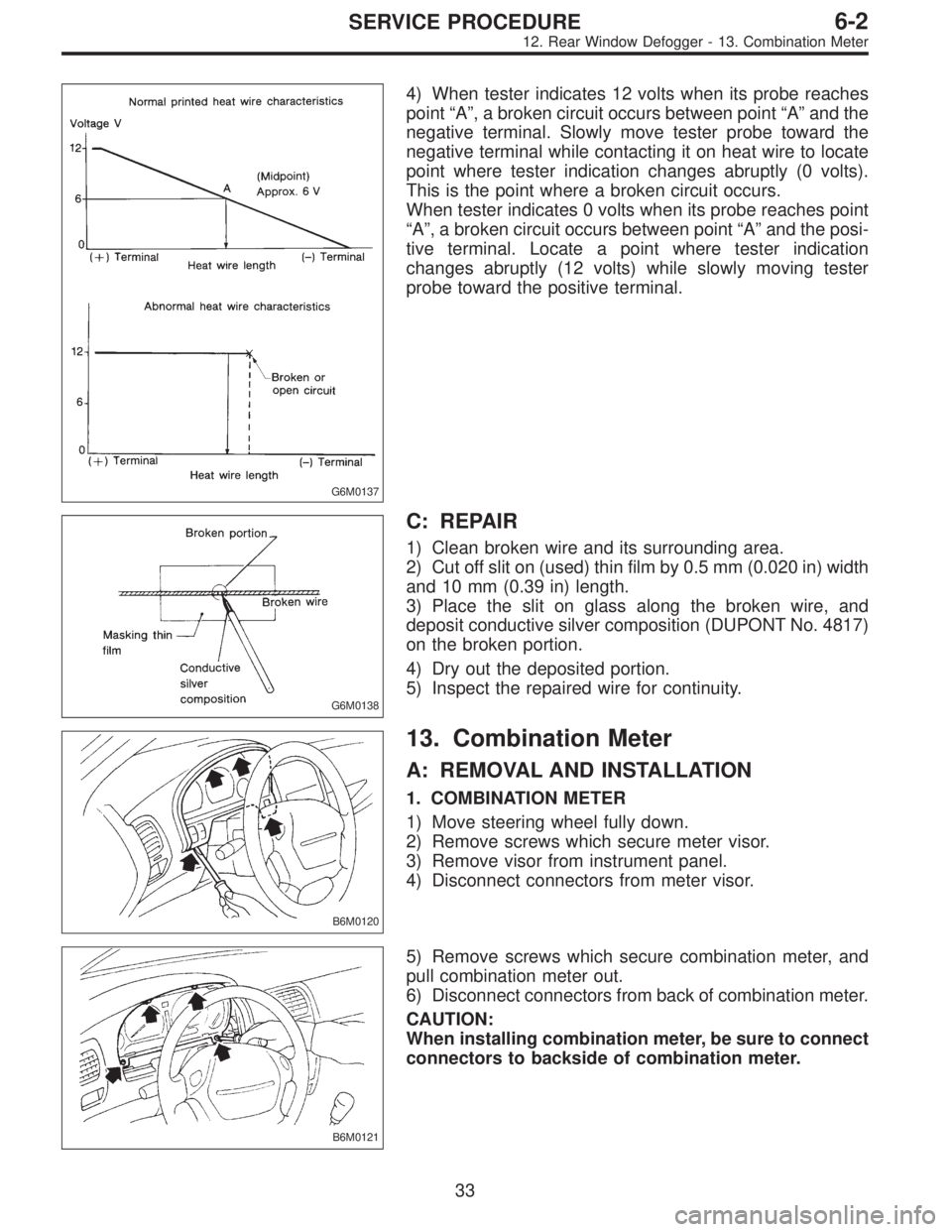
G6M0137
4) When tester indicates 12 volts when its probe reaches
point“A”, a broken circuit occurs between point“A”and the
negative terminal. Slowly move tester probe toward the
negative terminal while contacting it on heat wire to locate
point where tester indication changes abruptly (0 volts).
This is the point where a broken circuit occurs.
When tester indicates 0 volts when its probe reaches point
“A”, a broken circuit occurs between point“A”and the posi-
tive terminal. Locate a point where tester indication
changes abruptly (12 volts) while slowly moving tester
probe toward the positive terminal.
G6M0138
C: REPAIR
1) Clean broken wire and its surrounding area.
2) Cut off slit on (used) thin film by 0.5 mm (0.020 in) width
and 10 mm (0.39 in) length.
3) Place the slit on glass along the broken wire, and
deposit conductive silver composition (DUPONT No. 4817)
on the broken portion.
4) Dry out the deposited portion.
5) Inspect the repaired wire for continuity.
B6M0120
13. Combination Meter
A: REMOVAL AND INSTALLATION
1. COMBINATION METER
1) Move steering wheel fully down.
2) Remove screws which secure meter visor.
3) Remove visor from instrument panel.
4) Disconnect connectors from meter visor.
B6M0121
5) Remove screws which secure combination meter, and
pull combination meter out.
6) Disconnect connectors from back of combination meter.
CAUTION:
When installing combination meter, be sure to connect
connectors to backside of combination meter.
33
6-2SERVICE PROCEDURE
12. Rear Window Defogger - 13. Combination Meter