Page 1711 of 2890
21. Cruise Control
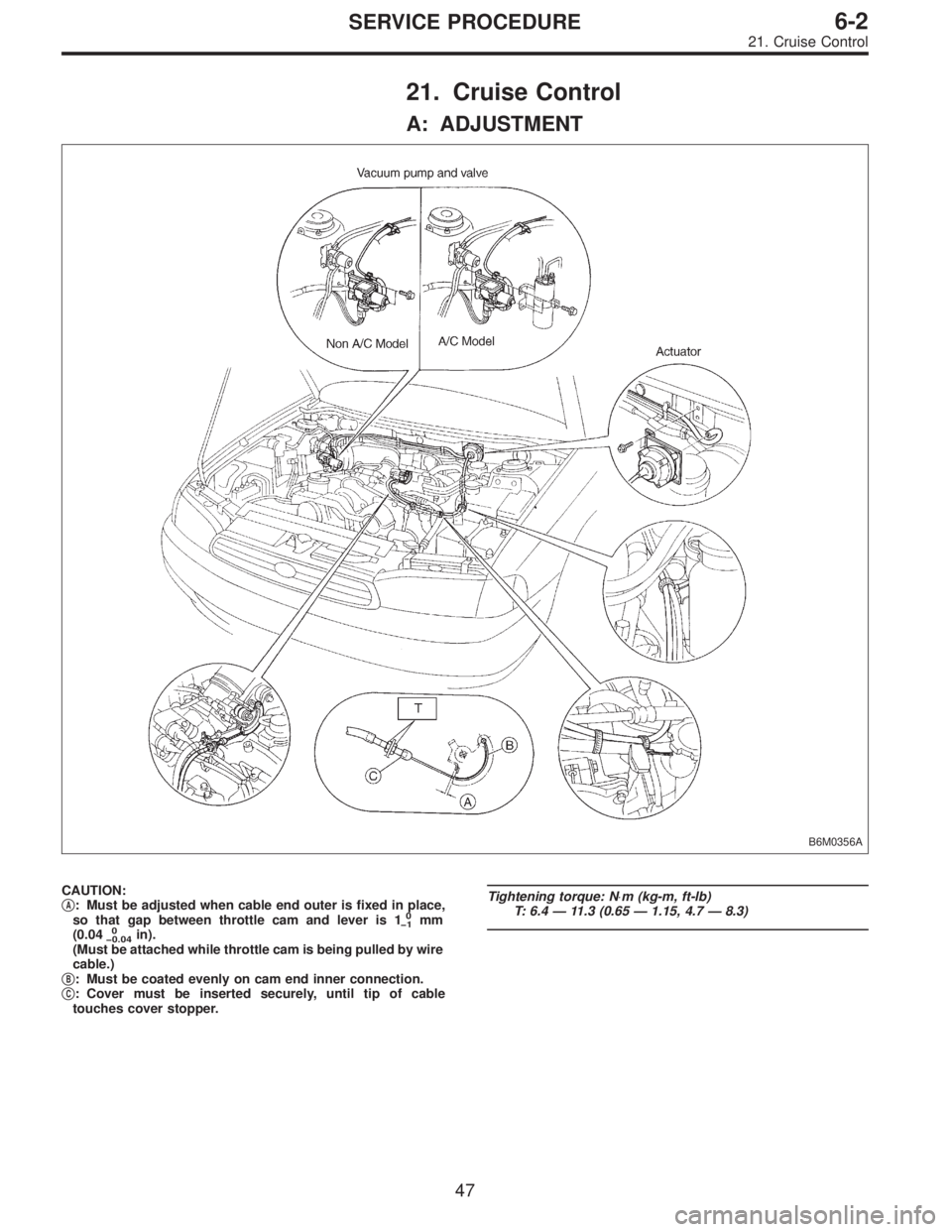
A: ADJUSTMENT
B6M0356A
CAUTION:
�A: Must be adjusted when cable end outer is fixed in place,
so that gap between throttle cam and lever is 10
�1mm
(0.040
�0.04in).
(Must be attached while throttle cam is being pulled by wire
cable.)
�
B: Must be coated evenly on cam end inner connection.
�C: Cover must be inserted securely, until tip of cable
touches cover stopper.
Tightening torque: N⋅m (kg-m, ft-lb)
T: 6.4—11.3 (0.65—1.15, 4.7—8.3)
47
6-2SERVICE PROCEDURE
21. Cruise Control
Page 1712 of 2890
 Remove screws which secure meter visor.
2) Remove meter visor from instrument panel while dis-
connecting connectors.
3) Remove cr")
B6M0154A
B: REMOVAL AND INSTALLATION
1. CRUISE CONTROL MAIN SWITCH
1) Remove screws which secure meter visor.
2) Remove meter visor from instrument panel while dis-
connecting connectors.
3) Remove cruise control main switch from meter visor.
B6M0357A
2. CRUISE CONTROL COMMAND SWITCH
1) Remove screw which secures horn pad to the base of
steering wheel.
2) Remove horn pad from steering wheel while discon-
necting connector.
3) Disconnect connector of cruise control command
switch.
4) Remove screws which secure cruise control command
switch to steering wheel, and then remove command
switch.
WARNING:
Refer to 5-5 when removing or installing the module
from the airbag equipped model.
B6M0156
3. ACTUATOR
1) Loosen nut which secures cruise control cable end to
throttle cam, and then remove cable from engine throttle
cam.
2) Remove clip bands from cruise control cable.
CAUTION:
�Be careful not to apply excessive load to the wire
cable when adjusting and/or installing; otherwise, the
actuator may be deformed or damaged.
�Do not bend cable sharply with a radius less than
100 mm (3.94 in); otherwise, cable may bend
permanently, resulting in poor performance.
�When installing cable, be careful not to sharply bend
or pinch the inner cable; otherwise, the cable may
break.
48
6-2SERVICE PROCEDURE
21. Cruise Control
Page 1713 of 2890
B6M0358
3) Remove nuts which secure actuator.
4) Remove actuator while disconnecting vacuum hose.
Tightening torque:
7.4±1.5 N⋅m (0.75±0.15 kg-m, 5.4±1.1 ft-lb)
B6M0359A
4. VACUUM PUMP AND VALVES
1) Disconnect connector from vacuum pump.
2) Remove bolts which secure vacuum pump.
3) Remove A/C receiver/drier bracket.
4) Remove vacuum pump while disconnecting vacuum
hose.
Tightening torque:
7.4±1.5 N⋅m (0.75±0.15 kg-m, 5.4±1.1 ft-lb)
5. STOP AND BRAKE SWITCH
Refer to 4-5 [C100] (MT) or 4-5 [C200] (AT) as for removal
and installation of stop and brake switch.
6. CLUTCH SWITCH (MT)
Refer to 4-5 [C100] as for removal and installation of clutch
switch.
7. INHIBITOR SWITCH (AT)
Refer to 3-2 [W4A3] as for removal and installation of
inhibitor switch.
G6M0095
8. CRUISE CONTROL MODULE
1) Disconnect battery ground cable.
B3M0377A
2) Remove lower cover and then disconnect connector.
49
6-2SERVICE PROCEDURE
21. Cruise Control
Page 1716 of 2890

B6M0361A
22. Security System
A: REMOVAL AND INSTALLATION
1. STARTER INTERRUPT RELAY
NOTE:
The starter interrupt relay and headlight alarm relay use the
same parts and are mounted parallel to each other.
Therefore, before removal and installation, identify the
starter interrupt relay by the color of its wiring connection.
1) Remove instrument panel lower cover.
2) Disconnect connector of starter interrupt relay.
3) Remove starter interrupt relay.
4) Installation is in the reverse order of removal.
B6M0361A
2. HEADLIGHT ALARM RELAY
NOTE:
The headlight alarm relay and starter interrupt relay use the
same parts and are mounted parallel to each other.
Therefore, before removal and installation, identify the
headlight alarm relay by the color of its wiring connection.
1) Remove instrument panel lower cover.
2) Disconnect connector of headlight alarm relay.
3) Remove headlight alarm relay.
4) Installation is in the reverse order of removal.
B6M0363A
3. ENGINE HOOD SWITCH
1) Disconnect connector of engine hood switch from bot-
tom side of switch body.
2) Remove headlight (LH).
3) Remove attaching bolt, and then remove engine hood
switch.
4) Installation is in the reverse order of removal.
52
6-2SERVICE PROCEDURE
22. Security System
Page 1717 of 2890
 Remove door trim panel a")
B6M0364A
4. KEY CYLINDER LOCK/UNLOCK SWITCH AND
TAMPER SWITCH
NOTE:
The key cylinder lock switch, unlock switch and tamper
switch are united in the switch body.
Door Switch
1) Remove door trim panel and sealing cover.
[W2A3].>
2) Disconnect connector of door key cylinder switch from
door cord.
3) Remove door outer handle.
CAUTION:
Be careful not to damage the door surface.
4) Remove clip, and then remove door key cylinder switch
from door outer handle.
5) Installation is in the reverse order of removal.
Trunk Lid Switch (SEDAN)
1) Disconnect connector of trunk lid key cylinder switch.
2) Disconnect rod from key cylinder.
3) Remove trunk lid key cylinder switch by pushing it.
4) Installation is in the reverse order of removal.
B6M0368A
Rear Gate Switch (WAGON)
1) Disconnect connector of rear gate key cylinder switch.
2) Disconnect rod from key cylinder.
3) Remove attaching bolts, and then remove rear gate key
cylinder switch.
4) Installation is in the reverse order of removal.
5. DOOR LOCK/UNLOCK SWITCH
NOTE:
The door lock/unlock switch is united with the power door
lock actuator.
Driver and Passenger Door
1) Remove door trim panel and sealing cover.
[W2A3].>
2) Disconnect connector of door lock actuator assembly
from door code.
53
6-2SERVICE PROCEDURE
22. Security System
Page 1718 of 2890
![SUBARU LEGACY 1996 Service Repair Manual 3) Remove door lock actuator assembly. <Ref. to 5-2
[W2A7].>
4) Installation is in the reverse order of removal.
Rear Gate (WAGON)
1) Remove rear gate trim panel.
2) Disconnect rod from rear gate latc](/manual-img/17/57433/w960_57433-1717.png "SUBARU LEGACY 1996 Service Repair Manual 3) Remove door lock actuator assembly. <Ref. to 5-2
[W2A7].>
4) Installation is in the reverse order of removal.
Rear Gate (WAGON)
1) Remove rear gate trim panel.
2) Disconnect rod from rear gate latc")
3) Remove door lock actuator assembly.
[W2A7].>
4) Installation is in the reverse order of removal.
Rear Gate (WAGON)
1) Remove rear gate trim panel.
2) Disconnect rod from rear gate latch assembly.
3) Disconnect rear gate switch connector and power door
lock actuator connector.
4) Remove bolts which secure power door lock actuator.
5) Remove bolts which secure latch.
6) Remove latch and actuator assembly.
7) Installation is in the reverse order of removal.
B6M0070A
6. DOOR SWITCH
1) Remove rubber boot of door switch.
2) Remove screw which secures door switch to body.
3) Remove door switch while disconnecting connector.
B6M0371A
7. TRUNK LID SWITCH (SEDAN)
NOTE:
The trunk lid switch is united with the trunk lid lock.
1) Remove trunk rear trim.
2) Disconnect connector of trunk switch (combined with
trunk room light switch).
3) Put matching mark on the trunk lid lock and vehicle
body before removal.
4) Remove bolts, then remove trunk lid lock from vehicle
body.
5) Installation is in the reverse order of removal.
NOTE:
Ensure that matching mark is aligned between trunk lid
lock and vehicle body.
54
6-2SERVICE PROCEDURE
22. Security System
Page 1719 of 2890

NOTE:
The rear gate switch is united with the rear gate latch
assembly.
1) Remove rear gate trim panel.
2) Disconnect rod from rear gate latch assembly.
3) Disconn")
B6M0372A
8. REAR GATE SWITCH (WAGON)
NOTE:
The rear gate switch is united with the rear gate latch
assembly.
1) Remove rear gate trim panel.
2) Disconnect rod from rear gate latch assembly.
3) Disconnect rear gate switch (combined with luggage
room light switch) connector and power door lock actuator
connector.
4) Remove bolts which secure power door lock actuator.
5) Remove bolts which secure latch.
6) Remove latch and actuator assembly.
7) Installation is in the reverse order of removal.
B6M0373A
9. SECURITY INDICATOR LIGHT
1) Remove screws which secure meter visor.
2) Remove meter visor from instrument panel while dis-
connecting connectors.
3) Remove security indicator light from meter visor.
4) Installation is in the reverse order of removal.
B6M0685A
10. SECURITY CONTROL MODULE
1) Remove instrument panel.
2) Remove bolt which secures security control module�
1.
3) Remove security control module while disconnecting
connector.
4) Installation is in the reverse order of removal.
Tightening torque:
7.4±2.0 N⋅m (0.75±0.2 kg-m, 5.4±1.4 ft-lb)
55
6-2SERVICE PROCEDURE
22. Security System
Page 1720 of 2890
 Disconnect connector of starter interrupt relay.
2) Connect battery to terminal No.1 and ground terminal
No. 2.
3) Check continuity between termina")
B6M0375A
B: INSPECTION
1. STARTER INTERRUPT RELAY
1) Disconnect connector of starter interrupt relay.
2) Connect battery to terminal No.1 and ground terminal
No. 2.
3) Check continuity between terminals as indicated in
table below:
When current flows. Between terminals
No. 3 and No. 5Continuity does not
exist.
When current does not flow. Between terminals
No. 3 and No. 5Continuity exists.
Between terminals
No. 1 and No. 2Continuity exists.
G6M0134
2. HEADLIGHT ALARM RELAY
1) Disconnect connector of headlight alarm relay.
2) Connect battery to terminal No. 1 and ground terminal
No. 2.
3) Check continuity between terminals as indicated in
table below:
When current flows. Between terminals
No. 3 and No. 5Continuity does not
exist.
Between terminals
No. 3 and No. 4Continuity exists.
When current does not flow. Between terminals
No. 3 and No. 5Continuity exists.
Between terminals
No. 3 and No. 4Continuity does not
exist.
Between terminals
No. 1 and No. 2Continuity exists.
B6M0376
3. ENGINE HOOD SWITCH
1) Disconnect connector of engine hood switch.
2) Check continuity between terminals when push rod is
pushed in 1.5 mm (0.059 in) of its stroke.
Terminal
Switch position12
When push rod is
pushed in.
When push rod is
released.��
56
6-2SERVICE PROCEDURE
22. Security System
 Remove nuts which secure actuator.
4) Remove actuator while disconnecting vacuum hose.
Tightening torque:
7.4±1.5 N⋅m (0.75±0.15 kg-m, 5.4±1.1 ft-lb)
B6M0359A
4. VACUUM PUMP AND VALVES")