Page 1767 of 2890
B6M0507A
2. CHECK POWER SUPPLY FOR HORN RELAY.
1) Check fuse No. 12.
2) Remove horn relay without disconnecting connector.
3) Measure voltage between horn relay connector and
body.
Connector & terminal / Specified voltage:
(B49) No. 2—Body / 10 V, or more
B6M0459
3. CHECK CONTINUITY OF HORN RELAY.
1) Remove horn relay.
2) Check continuity between terminals No. 1 and No. 2 of
horn relay.
B6M0501A
4. CHECK HARNESS CONNECTOR BETWEEN HORN
RELAY AND SECURITY CONTROL MODULE.
1) Disconnect connectors of horn relay and security con-
trol module.
2) Measure resistance of harness connector between horn
relay and security control module.
Connector & terminal / Specified resistance:
(B49) No. 1—(B93) No. 13 / 10Ω, max.
5. CHECK HORN RELAY.
Refer to 6-2 [W15B2] for inspection of horn relay.
103
6-2DIAGNOSTICS
6. Security System
Page 1768 of 2890

N: DIAGNOSTICS PROCEDURE FOR
HEADLIGHT ALARM SIGNAL
1. Check headlight alarm output signal for security
control module.
Not OK
�OK
5. Check headlight alarm relay.
OK Not OK
Repair or replace
wiring harness of
headlight circuit.
Replace headlight
alarm relay.
2. Check power supply for headlight alarm relay.
OK
�Not OK
Repair or replace wiring harness between
headlight alarm relay and battery.
3. Check continuity of headlight alarm relay.
OK
�Not OK
Replace headlight alarm relay.
4. Check harness connector between headlight
alarm relay and security control module.
OK
�Not OK
Repair or replace wiring harness between
headlight alarm relay and security control
module.
Replace security control module.
B6M0457A
1. CHECK HEADLIGHT ALARM OUTPUT SIGNAL
FOR SECURITY CONTROL MODULE.
1) Remove security control module without disconnecting
connector.
2) Measure voltage between security control module con-
nector and body.
Connector & terminal / Specified voltage:
(B93) No. 12—Body / 10 V, or more
3) Set security system in armed state.
4) Open the door without ignition key to operate the secu-
rity system (alarm state).
5) Measure voltage between security control module and
body during alarm state.
Connector & terminal / Specified voltage:
(B93) No. 12—Body / repeats 1 V, max. (0.2 sec.)
and 10 V, or more (0.6 sec.)
intervals
��
�
�
�
�
104
6-2DIAGNOSTICS
6. Security System
Page 1769 of 2890
B6M0508A
2. CHECK POWER SUPPLY FOR HEADLIGHT ALARM
RELAY.
1) Remove headlight alarm relay without disconnecting
connector.
2) Measure voltage between headlight alarm relay con-
nector and body.
Connector & terminal / Specified voltage:
(B58) No. 1—Body / 10 V, or more
B6M0455A
3. CHECK CONTINUITY OF HEADLIGHT ALARM
RELAY.
1) Remove headlight alarm relay.
2) Check continuity between terminals No. 1 and No. 2 of
headlight alarm relay.
B6M0502A
4. CHECK HARNESS CONNECTOR BETWEEN
HEADLIGHT ALARM RELAY AND SECURITY
CONTROL MODULE.
1) Disconnect connectors of headlight alarm relay and
security control module.
2) Measure resistance of harness connector between
headlight alarm relay and security control module.
Connector & terminal / Specified resistance:
(B58) No. 2—(B93) No. 12 / 10Ω, max.
5. CHECK HEADLIGHT ALARM RELAY.
Refer to 6-2 [W22B2] for inspection of headlight alarm
relay.
105
6-2DIAGNOSTICS
6. Security System
Page 1770 of 2890
 system detects and
indicates a fault in various inputs and outputs of the com-
plex electronic control. CHECK ENGINE malfunction indi-")
1. General
1. GENERAL DESCRIPTION
�The on-board diagnostics (OBD) system detects and
indicates a fault in various inputs and outputs of the com-
plex electronic control. CHECK ENGINE malfunction indi-
cator lamp (MIL) in the combination meter indicates occur-
rence of a fault or trouble.
�Further, against such a failure or sensors as may disable
the drive, the fail-safe function is provided to ensure the
minimal driveability.
�The OBD system incorporated with the vehicles within
this engine family complies with Section 1968.1, California
Code of Regulations (OBD-II regulation). The OBD system
monitors the components and the system malfunction
listed in Engine Section which affects on emissions.
�When the system decides that a malfunction occurs, MIL
illuminates. At the same time of the MIL illumination or
blinking, a diagnostic trouble code (DTC) and a freeze
frame engine conditions are stored into on-board com-
puter.
�The OBD system stores freeze frame engine condition
data (engine load, engine coolant temperature, fuel trim,
engine speed and vehicle speed, etc.) into on-board com-
puter when it detects a malfunction first.
�If the OBD system detects the various malfunctions
including the fault of fuel trim or misfire, the OBD system
first stores freeze frame engine conditions about the fuel
trim or misfire.
�When the malfunction does not occur again for three
consecutive trips, MIL is turned off, but DTC remains at
on-board computer.
�The OBD-II system is capable of communication with a
general scan tool (OBD-II general scan tool) formed by ISO
9141 CARB.
�The OBD-II diagnostics procedure is different from the
usual diagnostics procedure. When troubleshooting OBD-II
vehicles, connect Subaru select monitor or the OBD-II gen-
eral scan tool to the vehicle.
A: ENGINE
1. ENGINE AND EMISSION CONTROL SYSTEM
�The Multipoint Fuel Injection (MFI) system is a system
that supplies the optimum air-fuel mixture to the engine for
all the various operating conditions through the use of the
latest electronic technology.
With this system fuel, which is pressurized at a constant
pressure, is injected into the intake air passage of the cyl-
inder head. The injection quantity of fuel is controlled by an
intermittent injection system where the electro-magnetic
injection valve (fuel injector) opens only for a short period
of time, depending on the quantity of air required for one
cycle of operation. In actual operation, the injection quan-
2
2-7ON-BOARD DIAGNOSTICS II SYSTEM
1. General
Page 1825 of 2890
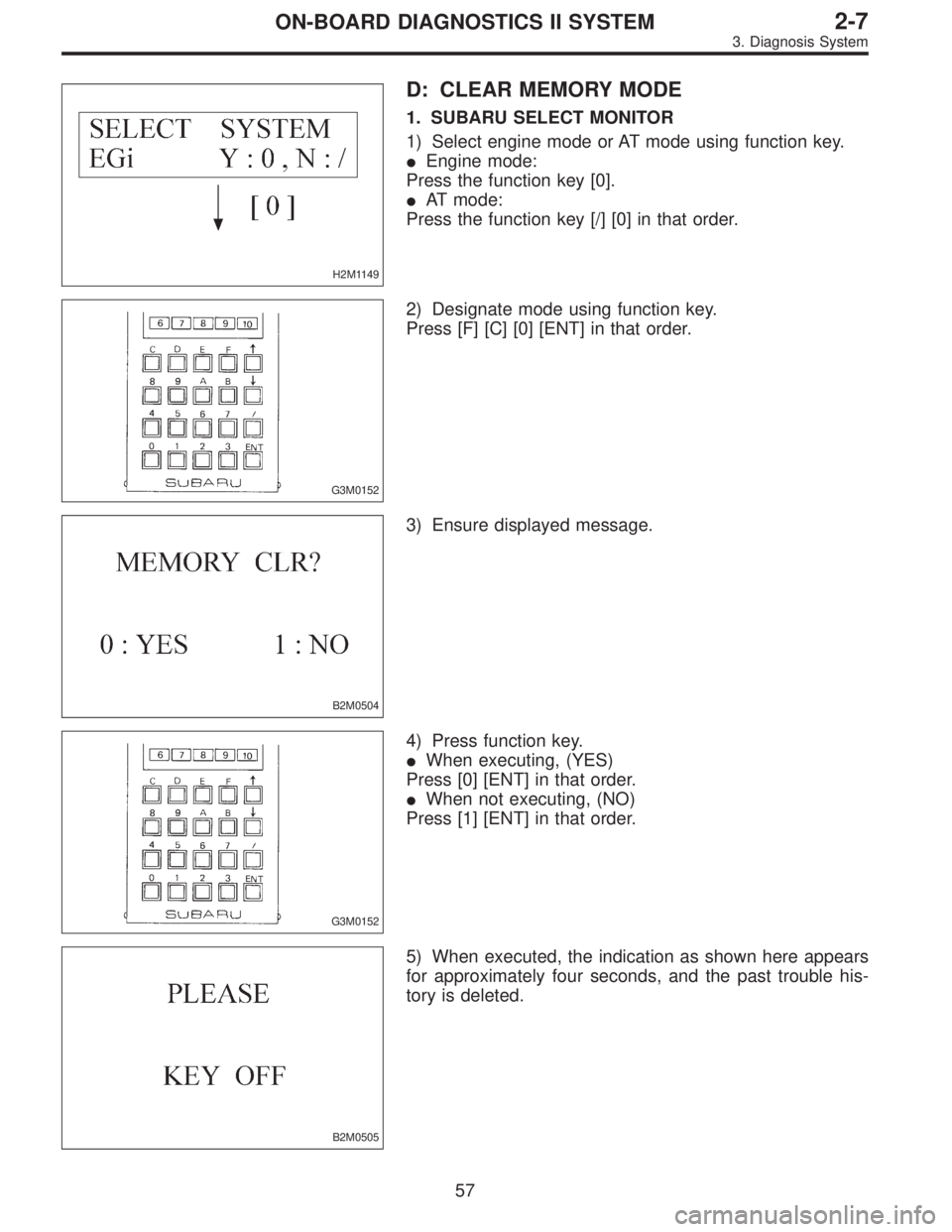
H2M1149
D: CLEAR MEMORY MODE
1. SUBARU SELECT MONITOR
1) Select engine mode or AT mode using function key.
�Engine mode:
Press the function key [0].
�AT mode:
Press the function key [/] [0] in that order.
G3M0152
2) Designate mode using function key.
Press [F] [C] [0] [ENT] in that order.
B2M0504
3) Ensure displayed message.
G3M0152
4) Press function key.
�When executing, (YES)
Press [0] [ENT] in that order.
�When not executing, (NO)
Press [1] [ENT] in that order.
B2M0505
5) When executed, the indication as shown here appears
for approximately four seconds, and the past trouble his-
tory is deleted.
57
2-7ON-BOARD DIAGNOSTICS II SYSTEM
3. Diagnosis System
Page 1826 of 2890
 After the display is gone, turn Subaru select monitor
switch and ignition switch to OFF.
NOTE:
When the ECM, battery terminals, etc. are disconnected
after memory is cleared, idling speed m")
G3M0151
6) After the display is gone, turn Subaru select monitor
switch and ignition switch to OFF.
NOTE:
When the ECM, battery terminals, etc. are disconnected
after memory is cleared, idling speed may increase. This is
not considered a problem because the ISC valve duty con-
trolled learning value has been cleared. To return the
engine to idling speed, idle for approximately 2 minutes
with air conditioner off.
2. OBD-II GENERAL SCAN TOOL
For clear memory procedures using the OBD-II general
scan tool, refer to the OBD-II General Scan Tool Instruction
Manual.
OBD0072A
E: INSPECTION MODE
1. PREPARATIONS FOR THE INSPECTION MODE
Raise the vehicle using a garage jack and place on safety
stands or drive the vehicle onto free rollers.
�FULL-TIME AWD MODELS
WARNING:
�Before raising the vehicle, ensure parking brakes
are applied.
�Do not use a pantograph jack in place of a safety
stand.
�Secure a rope or wire to the front and rear towing or
tie-down hooks to prevent the lateral runout of front
wheels.
�Do not abruptly depress/release clutch pedal or
accelerator pedal during works even when engine is
operating at low speeds since this may cause vehicle
to jump off free rollers.
�In order to prevent the vehicle from slipping due to
vibration, do not place any wooden blocks or similar
items between the safety stands and the vehicle.
58
2-7ON-BOARD DIAGNOSTICS II SYSTEM
3. Diagnosis System
Page 1827 of 2890

�Since the rear wheels will also rotate, do not place
anything near them. Also, make sure that nobody goes
in front of the vehicle.
OBD0073A
�FWD MODELS
WARNING:
�Before raising the vehicle, ensure parking brakes
are applied.
�Do not use a pantograph jack in place of a safety
stand.
�If only the front wheels are raised or placed on a free
roller, apply parking brakes and lock the rear wheels.
�Secure a rope or wire to the front and rear towing or
tie-down hooks to prevent the lateral runout of front
wheels.
�Do not abruptly depress/release clutch pedal or
accelerator pedal during works even when engine is
operating at low speeds since this may cause vehicle
to jump off free rollers.
�In order to prevent the vehicle from slipping due to
vibration, do not place any wooden blocks or similar
items between the safety stands and the vehicle.
�Since the rear wheels will also rotate, do not place
anything near them. Also, make sure that nobody goes
in front of the vehicle.
OBD0057A
2. SUBARU SELECT MONITOR
After performing diagnostics and clearing the memory,
check for any remaining unresolved trouble data.
1) Prepare Subaru select monitor and cartridge.
ST1 498307500 SELECT MONITOR KIT
ST2 498345700 CARTRIDGE
G3M0151
2) Turn ignition switch and Subaru select monitor switch to
OFF.
59
2-7ON-BOARD DIAGNOSTICS II SYSTEM
3. Diagnosis System
Page 1833 of 2890
OBD0060
6) Turn ignition switch to ON (engine OFF) and Subaru
select monitor switch to ON.
H2M1149
7) Select engine mode using function key.
Press the function key [0].
G3M0152
8) Designate mode using function key.
Refer to“6. READ DATA FUNCTION KEY LIST FOR
ENGINE”2-7 [T3C6].
(Example: Press [F] [D] [0] [5] [ENT] in that order.)
B2M0650
9) Ensure displayed message.
B2M0651
10) Press the function key.
(1) When executing, press the function key [0].
65
2-7ON-BOARD DIAGNOSTICS II SYSTEM
3. Diagnosis System
 Check fuse No. 12.
2) Remove horn relay without disconnecting connector.
3) Measure voltage between horn relay connector and
body.
Connector & termina")
 Remove headlight alarm relay without disconnecting
connector.
2) Measure voltage between headlight alarm relay con-
nector and body.
Connec")
![SUBARU LEGACY 1996 Service Repair Manual OBD0060
6) Turn ignition switch to ON (engine OFF) and Subaru
select monitor switch to ON.
H2M1149
7) Select engine mode using function key.
Press the function key [0].
G3M0152
8) Designate mode using](/manual-img/17/57433/w960_57433-1832.png "SUBARU LEGACY 1996 Service Repair Manual OBD0060
6) Turn ignition switch to ON (engine OFF) and Subaru
select monitor switch to ON.
H2M1149
7) Select engine mode using function key.
Press the function key [0].
G3M0152
8) Designate mode using")