Page 1963 of 2890
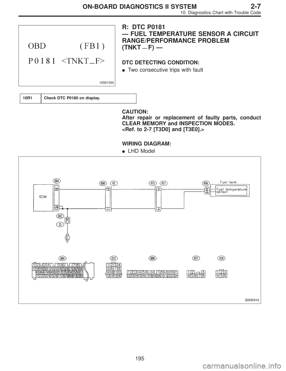
H2M1350
R: DTC P0181
—FUEL TEMPERATURE SENSOR A CIRCUIT
RANGE/PERFORMANCE PROBLEM
(TNKT
—F)—
DTC DETECTING CONDITION:
�Two consecutive trips with fault
10R1Check DTC P0180 on display.
CAUTION:
After repair or replacement of faulty parts, conduct
CLEAR MEMORY and INSPECTION MODES.
WIRING DIAGRAM:
�LHD Model
B2M0916
195
2-7ON-BOARD DIAGNOSTICS II SYSTEM
10. Diagnostics Chart with Trouble Code
Page 1971 of 2890
OBD0277
W: DTC P0301
—CYLINDER 1 MISFIRE DETECTED
(MIS
—1)—
OBD0278
X: DTC P0302
—CYLINDER 2 MISFIRE DETECTED
(MIS
—2)—
OBD0279
Y: DTC P0303
—CYLINDER 3 MISFIRE DETECTED
(MIS
—3)—
OBD0280
Z: DTC P0304
—CYLINDER 4 MISFIRE DETECTED
(MIS
—4)—
DTC DETECTING CONDITION:
�Two consecutive trips with fault
�Immediately at fault recognition (A misfire which could
damage catalyst occurs.)
TROUBLE SYMPTOM:
�Engine stalls.
�Erroneous idling
�Rough driving
203
2-7ON-BOARD DIAGNOSTICS II SYSTEM
10. Diagnostics Chart with Trouble Code
Page 1981 of 2890
 Turn ignition switch to OFF.
2) Disconnect connector from ECM.
3) Measure resistance between ECM harness connector
and chassis gr")
B2M0560A
10AA1CHECK HARNESS BETWEEN KNOCK
SENSOR AND ECM CONNECTOR.
1) Turn ignition switch to OFF.
2) Disconnect connector from ECM.
3) Measure resistance between ECM harness connector
and chassis ground.
: Connector & terminal
(B84) No. 3—Chassis ground:
Is the resistance more than 700 kΩ?
: Go to step10AA2.
: Go to next.
B2M0560A
: Connector & terminal
(B84) No. 3—Chassis ground:
Is the resistance less than 400 kΩ?
: Go to step10AA3.
: Go to step10AA4.
B2M0244A
10AA2
CHECK KNOCK SENSOR.
1) Disconnect connector from knock sensor.
2) Measure resistance between knock sensor connector
terminal and engine ground.
: Terminal
No. 1—Engine ground:
Is the resistance more than 700 kΩ?
: Go to next.
: Repair harness and connector.
NOTE:
In this case, repair the following:
�Open circuit in harness between knock sensor and ECM
connector
�Poor contact in knock sensor connector
�Poor contact in coupling connector (B21)
: Is the knock sensor installation bolt tight-
ened securely?
: Replace knock sensor.
: Tighten knock sensor installation bolt securely.
213
2-7ON-BOARD DIAGNOSTICS II SYSTEM
10. Diagnostics Chart with Trouble Code
Page 1985 of 2890
10AB2CHECK CRANKSHAFT POSITION SEN-
SOR.
: Is the crankshaft position sensor installa-
tion bolt tightened securely?
: Go to next step 1).
: Tighten crankshaft position sensor installation bolt
securely.
G2M0639
1) Remove crankshaft position sensor.
2) Measure resistance between connector terminals of
crankshaft position sensor.
: Terminals
No. 1—No. 2:
Is the resistance between 1 and 4 kΩ?
: Repair poor contact in crankshaft position sensor
connector.
: Replace crankshaft position sensor.
217
2-7ON-BOARD DIAGNOSTICS II SYSTEM
10. Diagnostics Chart with Trouble Code
Page 1988 of 2890
10AC2
CHECK CAMSHAFT POSITION SENSOR.
: Is the camshaft position sensor installation
bolt tightened securely?
: Go to next step 1).
: Tighten camshaft position sensor installation bolt
securely.
G2M0639
1) Remove camshaft position sensor.
2) Measure resistance between connector terminals of
camshaft position sensor.
: Terminals
No. 1—No. 2:
Is the resistance between 1 and 4 kΩ?
: Repair poor contact in camshaft position sensor
connector.
: Replace camshaft position sensor.
220
2-7ON-BOARD DIAGNOSTICS II SYSTEM
10. Diagnostics Chart with Trouble Code
Page 1989 of 2890
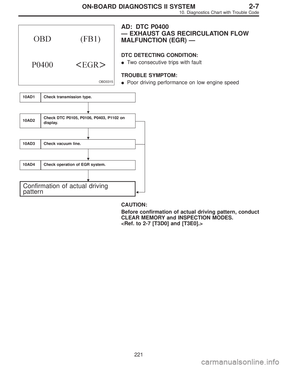
OBD0315
AD: DTC P0400
—EXHAUST GAS RECIRCULATION FLOW
MALFUNCTION (EGR)—
DTC DETECTING CONDITION:
�Two consecutive trips with fault
TROUBLE SYMPTOM:
�Poor driving performance on low engine speed
10AD1Check transmission type.
10AD2Check DTC P0105, P0106, P0403, P1102 on
display.
�
10AD3Check vacuum line.
10AD4Check operation of EGR system.
Confirmation of actual driving
pattern
CAUTION:
Before confirmation of actual driving pattern, conduct
CLEAR MEMORY and INSPECTION MODES.
�
�
�
�
221
2-7ON-BOARD DIAGNOSTICS II SYSTEM
10. Diagnostics Chart with Trouble Code
Page 1992 of 2890

B2M0647A
10AD3
CHECK VACUUM LINE.
: Is there a fault in vacuum line?
NOTE:
Check the following items.
�Disconnection, leakage and clogging of the two vacuum
hoses and pipes between throttle body and BPT
�Disconnection, leakage and clogging of the vacuum
hose and pipe between EGR solenoid valve and BPT
�Disconnection, leakage and clogging of the vacuum
hose between EGR solenoid valve and EGR valve
�Disconnection, leakage and clogging of BPT pressure
transmitting hose
: Repair or replace hoses and pipes.
And after the checking and repairing, go to
CON-
FIRMATION OF ACTUAL DRIVING
PATTERN.
: Go to step10AD4.
OBD0005B
10AD4
CHECK OPERATION OF EGR SYSTEM.
1) Turn ignition switch to OFF.
2) Connect the test mode connector.
3) Turn ignition switch to ON.
: Does EGR solenoid valve produce operating
sound?
NOTE:
EGR control solenoid valve operation check can also be
executed using Subaru Select Monitor (Function mode:
FD05). For the procedure, refer to“COMPULSORY VALVE
OPERATION CHECK MODE”2-7 [T3F0].
: Go to next step 4).
: Replace EGR solenoid valve.
4) Turn ignition switch to OFF.
5) Disconnect connector from EGR solenoid valve.
6) Connect 12 V battery’s ground�terminal to one ter-
minal of the EGR solenoid valve. Then connect 12 V bat-
tery’s�terminal to the other terminal of it.
CAUTION:
Do not use the 12 V battery installed in the vehicle,
because the electrical system may be damaged.
224
2-7ON-BOARD DIAGNOSTICS II SYSTEM
10. Diagnostics Chart with Trouble Code
Page 1995 of 2890
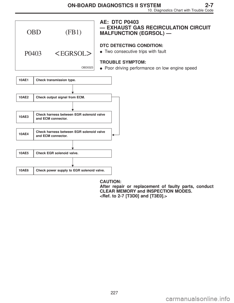
OBD0323
AE: DTC P0403
—EXHAUST GAS RECIRCULATION CIRCUIT
MALFUNCTION (EGRSOL)—
DTC DETECTING CONDITION:
�Two consecutive trips with fault
TROUBLE SYMPTOM:
�Poor driving performance on low engine speed
10AE1Check transmission type.
10AE2Check output signal from ECM.
�
10AE3Check harness between EGR solenoid valve
and ECM connector.
10AE4Check harness between EGR solenoid valve
and ECM connector.
10AE5Check EGR solenoid valve.
10AE6Check power supply to EGR solenoid valve.
CAUTION:
After repair or replacement of faulty parts, conduct
CLEAR MEMORY and INSPECTION MODES.
�
�
�
�
227
2-7ON-BOARD DIAGNOSTICS II SYSTEM
10. Diagnostics Chart with Trouble Code
—
OBD0278
X: DTC P0302
—CYLINDER 2 MISFIRE DETECTED
(MIS
—2)—
OBD0279
Y: DTC P0303
—CYLINDER 3 MISFIRE DETECTED
(MIS
—3)—
OB")
.
: Tighten crankshaft position sensor installation bolt
secure")
.
: Tighten camshaft position sensor installation bolt
securely.
G2M06")