Page 1834 of 2890
B2M0652
NOTE:
When in compulsory valve operation check mode the moni-
tor indicates the execution of valve check on display.
B2M0653
(2) When not executing or stopping the compulsory
valve check mode, press the function key [1].
B2M0643
11) When compulsory valve operation check mode is
exited or check completed, the monitor indicates the
completion of compulsory valve operation check on the
display, and automatically returns to the initial mode
(FUNCTION MODE: F00).
G3M0151
G: FINISHING DIAGNOSIS OPERATION
1. SUBARU SELECT MONITOR
1) Disconnect test mode connector at the lower portion of
instrument panel (on the driver’s side), to the side of the
center console box.
2) Turn Subaru select monitor switch and ignition switch to
OFF.
3) Disconnect Subaru select monitor from its data link con-
nector.
66
2-7ON-BOARD DIAGNOSTICS II SYSTEM
3. Diagnosis System
Page 1874 of 2890
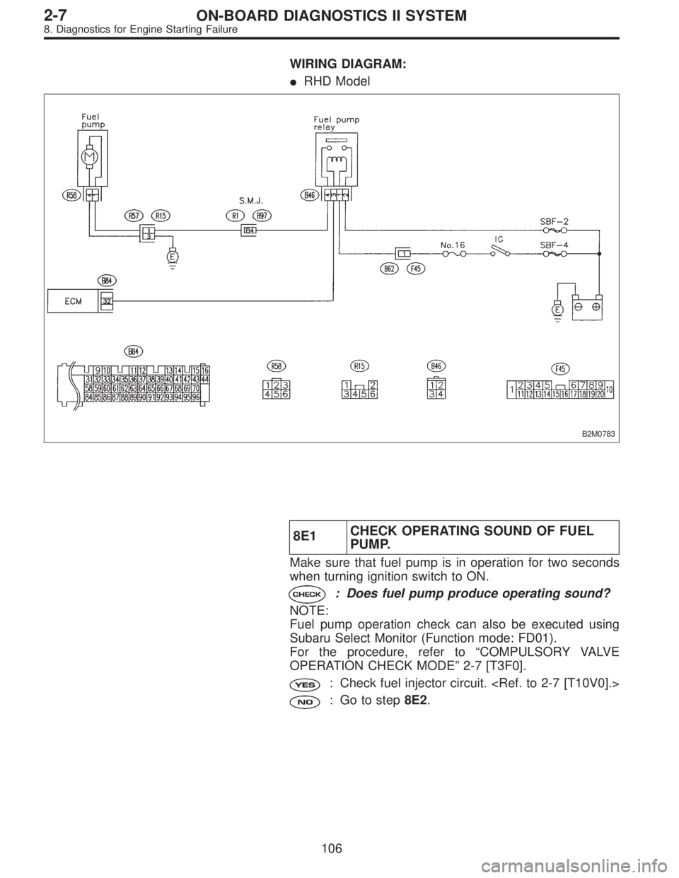
WIRING DIAGRAM:
�RHD Model
B2M0783
8E1CHECK OPERATING SOUND OF FUEL
PUMP.
Make sure that fuel pump is in operation for two seconds
when turning ignition switch to ON.
: Does fuel pump produce operating sound?
NOTE:
Fuel pump operation check can also be executed using
Subaru Select Monitor (Function mode: FD01).
For the procedure, refer to“COMPULSORY VALVE
OPERATION CHECK MODE”2-7 [T3F0].
: Check fuel injector circuit.
: Go to step8E2.
106
2-7ON-BOARD DIAGNOSTICS II SYSTEM
8. Diagnostics for Engine Starting Failure
Page 1883 of 2890
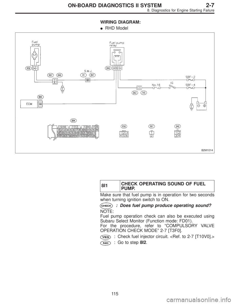
WIRING DIAGRAM:
�RHD Model
B2M1014
8I1CHECK OPERATING SOUND OF FUEL
PUMP.
Make sure that fuel pump is in operation for two seconds
when turning ignition switch to ON.
: Does fuel pump produce operating sound?
NOTE:
Fuel pump operation check can also be executed using
Subaru Select Monitor (Function mode: FD01).
For the procedure, refer to“COMPULSORY VALVE
OPERATION CHECK MODE”2-7 [T3F0].
: Check fuel injector circuit.
: Go to step8I2.
11 5
2-7ON-BOARD DIAGNOSTICS II SYSTEM
8. Diagnostics for Engine Starting Failure
Page 1886 of 2890

Throttle position sensor
Crankshaft position sensor & Camshaft po")
9. General Diagnostics Table
1. FOR ENGINE
12345678910111213
Problem parts
Mass air flow sensor
Engine coolant temperature sensor (*1)
Throttle position sensor
Crankshaft position sensor & Camshaft position sensor (*2)
Idle air control solenoid valve
Knock sensor
Purge control solenoid valve
EGR valve
Fuel injection parts (*3)
Ignition parts (*4)
Fuel pump and relay
A/C switch and A/C cut relay
Engine torque control signal circuitSymptom
1 Engine stalls during idling.�� � � ���
2 Rough idling�� � � � �
3 Engine does not return to idle.���
4 Poor acceleration�� � � ���
5Engine stalls or engine sags or hesi-
tates at acceleration.�� � � ��� �
6 Surge�� � �� �
7 Spark knock����
8 After burning in exhaust system�� � �
*1: The mark,�, indicates the symptom occurring only in cold temperatures.
*2: For items with the mark,�, ensure the secure installation of crankshaft position sensor and camshaft position sensor. Replacement is
not necessary.
*3: Check fuel injector, fuel pressure regulator and fuel filter.
*4: Check ignitor, ignition coil and spark plug.
NOTE:
Malfunction of parts other than the above is also possible. Refer to 1. Engine Trouble in General [K100] in Repair Section 2-3 or 2-3b of
the Service Manual.
11 8
2-7ON-BOARD DIAGNOSTICS II SYSTEM
9. General Diagnostics Table
Page 1900 of 2890
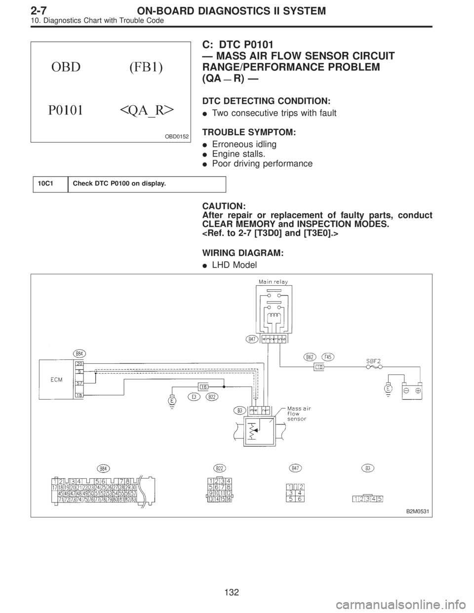
OBD0152
C: DTC P0101
—MASS AIR FLOW SENSOR CIRCUIT
RANGE/PERFORMANCE PROBLEM
(QA
—R)—
DTC DETECTING CONDITION:
�Two consecutive trips with fault
TROUBLE SYMPTOM:
�Erroneous idling
�Engine stalls.
�Poor driving performance
10C1Check DTC P0100 on display.
CAUTION:
After repair or replacement of faulty parts, conduct
CLEAR MEMORY and INSPECTION MODES.
WIRING DIAGRAM:
�LHD Model
B2M0531
132
2-7ON-BOARD DIAGNOSTICS II SYSTEM
10. Diagnostics Chart with Trouble Code
Page 1910 of 2890
B2M0654
E: DTC P0106
—PRESSURE SENSOR CIRCUIT
RANGE/PERFORMANCE PROBLEM (PS
—R)
—
DTC DETECTING CONDITION:
�Two consecutive trips with fault
10E1Check DTC P0105 or P1102 on display.
10E2Check data for control.
10E3Check vacuum hose.
10E4Check pressure sources switching solenoid
valve.
CAUTION:
After repair or replacement of faulty parts, conduct
CLEAR MEMORY and INSPECTION MODES.
�
�
�
142
2-7ON-BOARD DIAGNOSTICS II SYSTEM
10. Diagnostics Chart with Trouble Code
Page 1914 of 2890

B2M0711A
10E3
CHECK VACUUM HOSE.
: Is there a fault in vacuum hose?
NOTE:
Check the following items.
�Disconnection of the vacuum hose from pressure
sources switching solenoid valve to intake manifold
�Holes in the vacuum hose between pressure sources
switching solenoid valve to intake manifold
�Clogging of the vacuum hose between pressure sources
switching solenoid valve to intake manifold
�Disconnection of the vacuum hose from pressure sensor
to pressure sources switching solenoid valve
�Holes in the vacuum hose between pressure sensor and
pressure sources switching solenoid valve
�Clogging of the vacuum hose between pressure sensor
and pressure sources switching solenoid valve
�Clogging of the filter
: Repair or replace hoses or filter.
: Go to step10E4.
OBD0005B
10E4CHECK PRESSURE SOURCES SWITCH-
ING SOLENOID VALVE.
1) Turn ignition switch to OFF.
2) Connect test mode connector.
3) Turn ignition switch to ON.
: Does pressure sources switching solenoid
valve produce operating sound? (ON↔
OFF each 1.5 sec.)
NOTE:
Pressure sources switching solenoid valve operation check
can also be executed using Subaru Select Monitor (Func-
tion mode: FD10). For the procedure, refer to“COMPUL-
SORY VALVE OPERATION CHECK MODE”2-7 [T3F0].
: Replace pressure sensor.
: Replace pressure sources switching solenoid
valve.
146
2-7ON-BOARD DIAGNOSTICS II SYSTEM
10. Diagnostics Chart with Trouble Code
Page 1925 of 2890
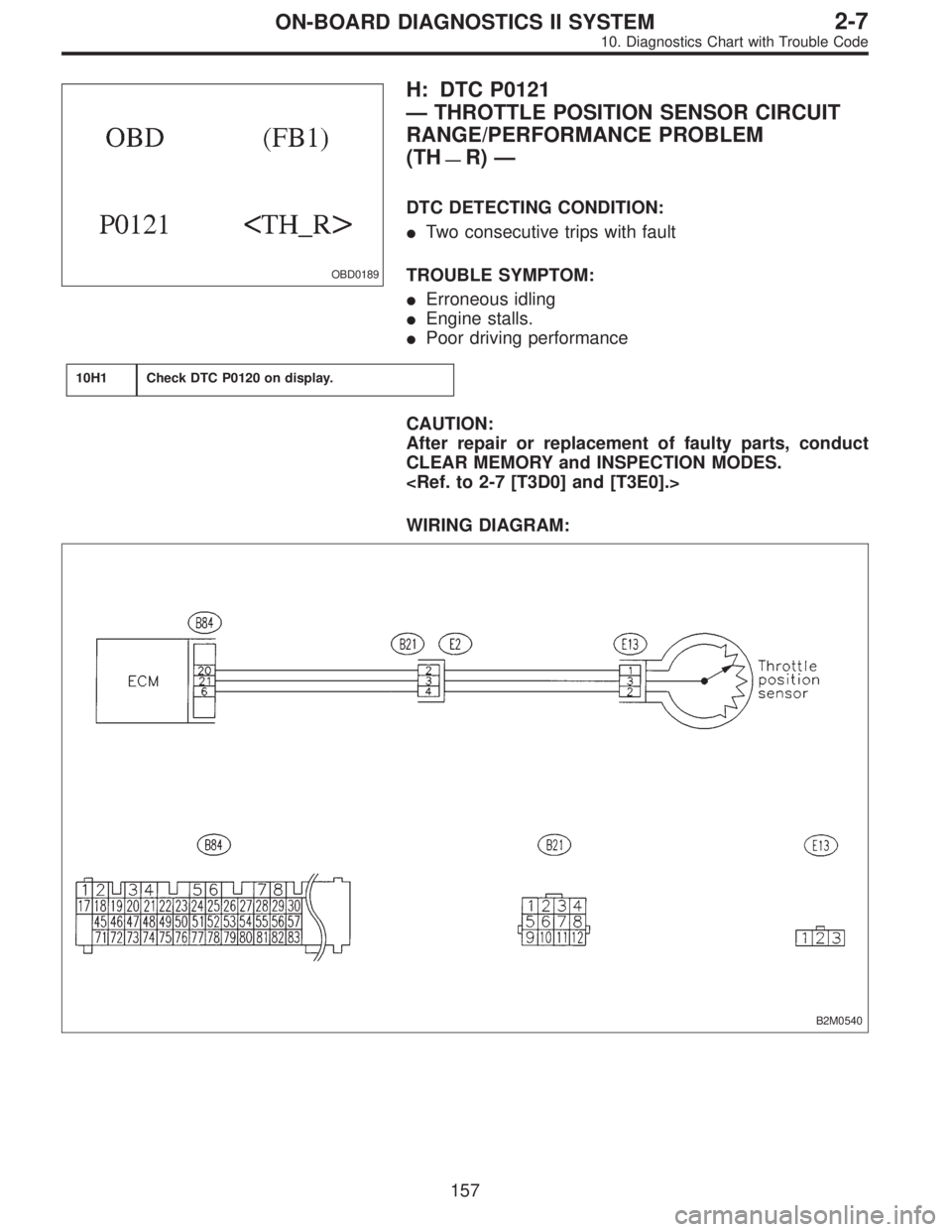
OBD0189
H: DTC P0121
—THROTTLE POSITION SENSOR CIRCUIT
RANGE/PERFORMANCE PROBLEM
(TH
—R)—
DTC DETECTING CONDITION:
�Two consecutive trips with fault
TROUBLE SYMPTOM:
�Erroneous idling
�Engine stalls.
�Poor driving performance
10H1Check DTC P0120 on display.
CAUTION:
After repair or replacement of faulty parts, conduct
CLEAR MEMORY and INSPECTION MODES.
WIRING DIAGRAM:
B2M0540
157
2-7ON-BOARD DIAGNOSTICS II SYSTEM
10. Diagnostics Chart with Trouble Code
 When not executing or stopping the compulsory
valve check mode,")