Page 1346 of 2890
4. ACCELERATOR AND BRAKE PEDAL (RHD
MODEL)
1) Disconnect negative cable from battery.
2) Disconnect accelerator cable from throttle body.
CAUTION:
Be careful not to kink accelerator cable.
3) Remove instrument panel lower cover from instrument
panel.
4) Remove clevis pin which secures brake pedal to brake
booster operating rod. Also disconnect electrical connec-
tors (for stop light switch, etc.).
G4M0322
5) Disconnect accelerator cable from accelerator pedal
lever.
B4M0156A
6) Remove the casing cap out of the toe board by turning
it clockwise.
7) Pull out the cable from the toe board hole.
10
4-5SERVICE PROCEDURE
1. Pedal
Page 1347 of 2890
B4M0157A
8) Remove nuts and bolts which secure pedal bracket.
11
4-5SERVICE PROCEDURE
1. Pedal
Page 1350 of 2890
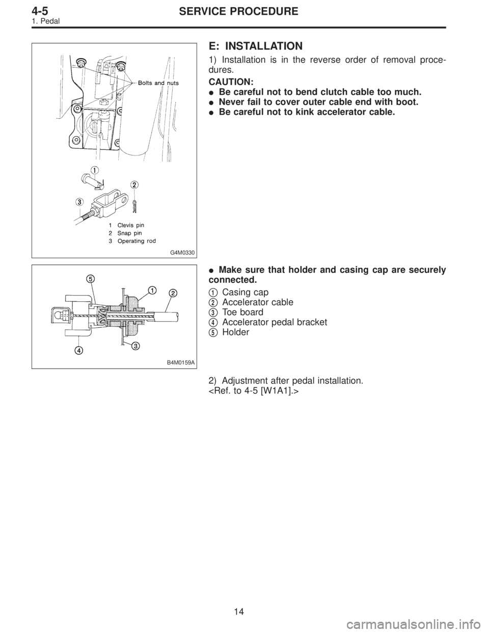
G4M0330
E: INSTALLATION
1) Installation is in the reverse order of removal proce-
dures.
CAUTION:
�Be careful not to bend clutch cable too much.
�Never fail to cover outer cable end with boot.
�Be careful not to kink accelerator cable.
B4M0159A
�Make sure that holder and casing cap are securely
connected.
�
1Casing cap
�
2Accelerator cable
�
3Toe board
�
4Accelerator pedal bracket
�
5Holder
2) Adjustment after pedal installation.
14
4-5SERVICE PROCEDURE
1. Pedal
Page 1353 of 2890
 Disconnect accelerator cable from connector inside
engine compartment first.
G2M0280
2) Remove lock nut from accelerator cable bracket.
3) Separate accelerator cable�
1from bracket, then")
A: REMOVAL
1) Disconnect accelerator cable from connector inside
engine compartment first.
G2M0280
2) Remove lock nut from accelerator cable bracket.
3) Separate accelerator cable�
1from bracket, then unlock
inner cable.
4) Remove cable end from throttle cam using your finger-
tips.
CAUTION:
Be careful not to bend inner cable.
5) Disconnect cable end from accelerator cable bracket
inside driver compartment.
6) Remove clip inside engine compartment.
G4M0335
7) Working inside engine compartment, remove the casing
cap out of the toe board by turning it clockwise.
8) Pull out the cable from the toe board hole.
B: INSTALLATION
1) Installation is in the reverse order of removal proce-
dures.
CAUTION:
�Be careful not to kink accelerator cable.
�Make sure that holder and casing cap are securely
connected.
B4M0159A
�1Casing cap
�
2Accelerator cable
�
3Toe board
�
4Accelerator pedal bracket
�
5Holder
2) Adjustment after cable installation.
17
4-5SERVICE PROCEDURE
3. Accelerator Cable
Page 1370 of 2890
RHD model
Terminal
No.Mode selector switch RECIRC switch
A/C
switchIllumi.
VENT BI-LEV HEATDEF/
HEATDEF RECIRC FRESH
1�
2�
3�
4�
5�
6�
7�
8�
9������
10�
11
12�
13��������
14�
15
16�
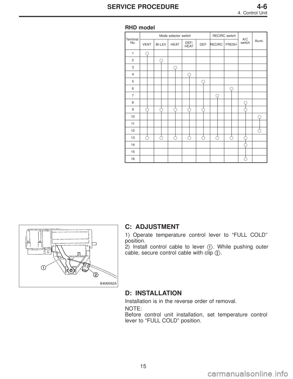
B4M0062A
C: ADJUSTMENT
1) Operate temperature control lever to“FULL COLD”
position.
2) Install control cable to lever�
1. While pushing outer
cable, secure control cable with clip�
2.
D: INSTALLATION
Installation is in the reverse order of removal.
NOTE:
Before control unit installation, set temperature control
lever to“FULL COLD”position.
15
4-6SERVICE PROCEDURE
4. Control Unit
Page 1371 of 2890
B5M0025
5. Intake Door Motor
A: REMOVAL
1) Disconnect GND cable from battery.
2) Remove glove box and pocket back panel.
[W1A0].>
3) Remove heater duct or evaporator. (With A/C model).
G4M0561
4) Remove intake unit from the vehicle.
G4M0562
5) Remove screws which secure intake door motor to
intake unit.
NOTE:
Ensure that RECIRC switch is set to“ON”.
B4M0294A
B: INSPECTION
1) When approx. 12 V is applied to the intake door motor
terminals, intake door motor operates as follows:
LHD model
Intake
door motor
positionTerminal
Intake door motor operation
��
FRESH
32 Door motor moved to FRESH position.
RECIRC 1 Door motor moved to RECIRC position.
RHD model
Intake
door motor
positionTerminal
Intake door motor operation
��
FRESH
21 Door motor moved to FRESH position.
RECIRC 3 Door motor moved to RECIRC position.
16
4-6SERVICE PROCEDURE
5. Intake Door Motor
Page 1372 of 2890
G4M0564
2) Connect harness to intake door motor.
3) Turn ignition switch to“ACC”and RECIRC switch to
“ON”then, set to“RECIRC”.
NOTE:
Ensure that intake door motor is set in the“RECIRC”mode.
4) Install intake door motor on intake unit.
5) Secure rod holder to link, and install link to intake unit.
6) Manually set rod in the“RECIRC”mode, and secure to
rod holder.
7) Operate mode selector switch to ensure that system
changes from intake air to“RECIRC”and from“RECIRC”
to intake air in full-stroke range.
C: INSTALLATION
Installation is in the reverse order of removal.
17
4-6SERVICE PROCEDURE
5. Intake Door Motor
Page 1405 of 2890
B4M0760A
B: REMOVAL
1) Disconnect ground cable from battery.
2) Discharge refrigerant using refrigerant recovery system.
(1) Fully close low-pressure valve of manifold gauge.
(2) Connect low-pressure charging hose of manifold
gauge to low-pressure service valve.
(3) Open low-pressure manifold gauge valve slightly,
and slowly discharge refrigerant from system.
CAUTION:
Do not allow refrigerant to rush out. Otherwise, com-
pressor oil will be discharged along with refrigerant.
B4M0761A
3) Remove low-pressure hose�1(Flexible hose Ps) and
high-pressure hose�
2(Flexible hose Pd).
CAUTION:
�Be careful not to lose O-ring of low-pressure hose.
�Plug the opening to prevent foreign matter from
entering.
G4M0624
4) Remove compressor belt cover and alternator belt
cover.
Remove bolts which secure belt covers.
G4M0625
5) Remove alternator V-belt.
Loosen lock bolt on alternator bracket. Turn adjusting bolt
and remove V-belt.
31
4-7SERVICE PROCEDURE
11. Compressor

1) Disconnect negative cable from battery.
2) Disconnect accelerator cable from throttle body.
CAUTION:
Be careful not to kink accelerator cable.
3) Remove i")
 Remove nuts and bolts which secure pedal bracket.
11
4-5SERVICE PROCEDURE
1. Pedal")
![SUBARU LEGACY 1996 Service Repair Manual B5M0025
5. Intake Door Motor
A: REMOVAL
1) Disconnect GND cable from battery.
2) Remove glove box and pocket back panel. <Ref. to 5-4
[W1A0].>
3) Remove heater duct or evaporator. (With A/C model).
<R](/manual-img/17/57433/w960_57433-1370.png "SUBARU LEGACY 1996 Service Repair Manual B5M0025
5. Intake Door Motor
A: REMOVAL
1) Disconnect GND cable from battery.
2) Remove glove box and pocket back panel. <Ref. to 5-4
[W1A0].>
3) Remove heater duct or evaporator. (With A/C model).
<R")
 Connect harness to intake door motor.
3) Turn ignition switch to“ACC”and RECIRC switch to
“ON”then, set to“RECIRC”.
NOTE:
Ensure that intake door motor is set in the“RECIRC”")
![SUBARU LEGACY 1996 Service Repair Manual B4M0760A
B: REMOVAL
1) Disconnect ground cable from battery.
2) Discharge refrigerant using refrigerant recovery system.
<Ref. to 4-7 [W601].>
(1) Fully close low-pressure valve of manifold gauge.
(2)](/manual-img/17/57433/w960_57433-1404.png "SUBARU LEGACY 1996 Service Repair Manual B4M0760A
B: REMOVAL
1) Disconnect ground cable from battery.
2) Discharge refrigerant using refrigerant recovery system.
<Ref. to 4-7 [W601].>
(1) Fully close low-pressure valve of manifold gauge.
(2)")