Page 1406 of 2890
G4M0626
6) Remove compressor V-belt.
Loosen lock nut on idler pulley. Turn adjusting bolt and
remove V-belt.
G4M0627
7) Disconnect alternator harness.
G4M0628
8) Disconnect compressor harness.
Disconnect compressor harness from body harness.
9) Lower bracket.
Remove bolts which secure lower compressor bracket.
G4M0629
10) Remove compressor.
Remove bolt which secure compressor. Remove compres-
sor from bracket.
G4M0630
C: INSTALLATION
1) Install compressor.
Install compressor on bracket.
32
4-7SERVICE PROCEDURE
11. Compressor
Page 1407 of 2890
 Connect compressor harness.
3) Connect alternator harness.
4) Install compressor V-belt (Rear).
After adjusting belt tension, tighten tension pulley lock nut
securely.
G4M0632
5) Install alternator")
2) Connect compressor harness.
3) Connect alternator harness.
4) Install compressor V-belt (Rear).
After adjusting belt tension, tighten tension pulley lock nut
securely.
G4M0632
5) Install alternator V-belt.
After adjusting V-belt tension, tighten alternator bracket
lock bolt securely.
6) Check drive belt tension and adjust it if necessary by
changing alternator position and/or idler pulley position.
Pulley arrangement Tension mm (in)/98N (10 kg, 22 lb)
G4M0939
AB
*New belt:
7.0—9.0
(0.276—0.354)
Existing belt:
9.0—11.0
(0.354—0.433)*New belt:
7.5—8.5
(0.295—0.335)
Existing belt:
9.0—10.0
(0.354—0.394)
* When replacing belts with new ones, adjust tensions to
specification and then readjust to the same specification
after running engine for 5 minutes.
Figures in table refer to the number of grooves in pulleys.
C/P : Crankshaft pulley
ALT : Alternator pulley
P/S : Power steering oil pump pulley
A/C : Air conditioner compressor pulley
I/P : Idler pulley
33
4-7SERVICE PROCEDURE
11. Compressor
Page 1409 of 2890
B4M0095
12. Condenser
A: REMOVAL AND INSTALLATION
1) Disconnect battery negative terminal.
2) Discharge refrigerant using refrigerant recovery system.
3) Remove front grille.
G2M0375
4) Remove canister from bracket.
CAUTION:
�Do not disconnect hose from canister.
�Insert air vent hose of canister into the hole on body.
B4M0096A
5) Remove the radiator upper bracket of both side.
6) Disconnect high-pressure hose�
1and high-pressure
pipe�
2from condenser.
B4M0097
7) Remove the two bolts which secure condenser. While
lifting condenser, remove it through space between radia-
tor and radiator panel.
B4M0098A
8) The condenser should be installed in the reverse order
in which it was removed.
When installing the condenser, pay attention to the follow-
ing:
CAUTION:
Before connecting the pipe, be sure to apply oil to the
periphery of O-ring.
35
4-7SERVICE PROCEDURE
12. Condenser
Page 1462 of 2890

1. Hood
The hood lock has a dual locking design which consists of
a main lock and a safety lock mechanism. When the
release knob located at the front pillar on the driver’s side
is pulled back, the main lock is released through the cable
attached to the knob.
The safety lock can be released by pushing the lever pro-
truding above the front grill while opening the hood.
G5M0137
A: REMOVAL
1. HOOD
1) Open front hood, and remove washer hose.
2) Remove attaching bolts.
3) Detach front hood from hinges.
B5M0267
2. HOOD LOCK
1) Open front hood and remove front grille.
2) Remove bolts which secure lock assembly to radiator
panel, and remove lock assembly.
3) Disconnect release cable from lock assembly.
B5M0319
3. RELEASE CABLE
1) Remove front grille.
2) Remove release cable from opener lever in passenger
compartment.
3) Remove release cable from lock assembly.
4) Remove cable clip from engine compartment.
G5M0140
B: POINTS TO CHECK
1) Check striker for bending or abnormal wear.
2) Check safety lever for improper movement.
3) Check other levers and spring for rust formation and
unsmooth movement.
33
5-1SERVICE PROCEDURE
1. Hood
Page 1480 of 2890
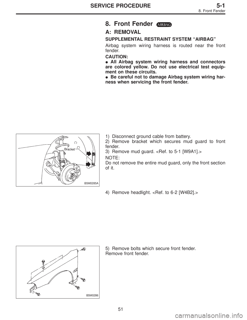
8. Front Fender
A: REMOVAL
SUPPLEMENTAL RESTRAINT SYSTEM“AIRBAG”
Airbag system wiring harness is routed near the front
fender.
CAUTION:
�All Airbag system wiring harness and connectors
are colored yellow. Do not use electrical test equip-
ment on these circuits.
�Be careful not to damage Airbag system wiring har-
ness when servicing the front fender.
B5M0285A
1) Disconnect ground cable from battery.
2) Remove bracket which secures mud guard to front
fender.
3) Remove mud guard.
NOTE:
Do not remove the entire mud guard, only the front section
of it.
4) Remove headlight.
B5M0286
5) Remove bolts which secure front fender.
Remove front fender.
51
5-1SERVICE PROCEDURE
8. Front Fender
Page 1489 of 2890
 Remove bracket which secures m")
B5M0411A
14. Side Protector
A: REMOVAL
Side protector consists of three parts; front fender, front
door and rear door.
B5M0285A
1. SIDE PROTECTOR FRONT FENDER PORTION
1) Remove bracket which secures mud guard to front
fender.
2) Remove mud guard.
NOTE:
Detach the rear part of mud guard as required for the pro-
cedure. It is not necessary to remove the entire mud guard.
3) Use pliers to remove a clip from inside front fender.
Remove it from vehicle body but keep it with side protec-
tor.
2. SIDE PROTECTOR FRONT DOOR AND REAR
DOOR PORTIONS
1) Remove door trim panel.
2) Use pliers to remove clips from inside of doors. Remove
them from vehicle body but keep them with side protector.
NOTE:
Front door portion has five clips, rear door portion has four
clips.
B: INSTALLATION
Installation is in the reverse order of removal.
NOTE:
To install side protector front door and rear door portions,
insert the first clip into the base hole [9 mm (0.35 in) dia.],
and then insert other clips.
CAUTION:
Insert clips firmly and carefully by hand. To avoid dam-
aging clips, do not forcefully push or hit clips.
57
5-1SERVICE PROCEDURE
14. Side Protector
Page 1492 of 2890
B5M0310A
3. SUNROOF FRAME
1) Remove sunroof switch, center and rear room lamps.
2) Remove roof trim, rear quarter trim, pillar trim, etc.
3) Remove glass lid assembly.
4) Remove two harness support clips.
G5M0205
5) Disconnect harness clips and connector of sunroof
motor.
6) Disconnect front and rear drain tubes.
CAUTION:
When installing drain tube, insert it securely into drain
pipe.
Length A:
15 mm (0.59 in) or more
B5M0312
7) Remove eight nuts.
B5M0382A
8) Remove set bracket mounting bolts.
9) Remove sunroof frame.
B: INSTALLATION
Installation is in the reverse order of removal.
59
5-1SERVICE PROCEDURE
16. Sunroof
Page 1515 of 2890
G5M0486
2. Door
A: REMOVAL AND INSTALLATION
1. DOOR ASSY
1) Remove lower trim and disconnect connectors from
body harness.
2) Place a cloth or a wood block under door to prevent
damage, and support it with a jack.
3) Remove checker pin by driving it upward. Be careful not
to damage door and body.
G5M0385
4) Remove bolts (M8) securing upper and lower hinges to
door, and remove door from hinges.
Tightening torque:
25±3 N⋅m (2.5±0.3 kg-m, 18.1±2.2 ft-lb)
5) Remove hinges by loosening hinges mounting bolt (M8)
off of body.
Tightening torque:
29±5 N⋅m (3.0±0.5 kg-m, 21.7±3.6 ft-lb)
CAUTION:
Work carefully to avoid damaging door.
6) Installation is in the reverse order of removal.
NOTE:
Apply grease to moving parts of door hinges.
B5M0329A
2. TRIM PANEL
1) Press retainer spring�
1with a thin flat bladed screw-
driver and then remove regulator handle�
2. (models with-
out power window)
B5M0061A
2) Remove gusset cover�1and three screws.
13
5-2SERVICE PROCEDURE
2. Door
 Remove compressor V-belt.
Loosen lock nut on idler pulley. Turn adjusting bolt and
remove V-belt.
G4M0627
7) Disconnect alternator harness.
G4M0628
8) Disconnect compressor harness.
Disconn")
![SUBARU LEGACY 1996 Service Repair Manual B4M0095
12. Condenser
A: REMOVAL AND INSTALLATION
1) Disconnect battery negative terminal.
2) Discharge refrigerant using refrigerant recovery system.
<Ref. to 4-7 [W601].>
3) Remove front grille.
G2M](/manual-img/17/57433/w960_57433-1408.png "SUBARU LEGACY 1996 Service Repair Manual B4M0095
12. Condenser
A: REMOVAL AND INSTALLATION
1) Disconnect battery negative terminal.
2) Discharge refrigerant using refrigerant recovery system.
<Ref. to 4-7 [W601].>
3) Remove front grille.
G2M")
![SUBARU LEGACY 1996 Service Repair Manual B5M0310A
3. SUNROOF FRAME
1) Remove sunroof switch, center and rear room lamps.
2) Remove roof trim, rear quarter trim, pillar trim, etc.
<Ref. to 5-3 [W5A0].>
3) Remove glass lid assembly.
4) Remove](/manual-img/17/57433/w960_57433-1491.png "SUBARU LEGACY 1996 Service Repair Manual B5M0310A
3. SUNROOF FRAME
1) Remove sunroof switch, center and rear room lamps.
2) Remove roof trim, rear quarter trim, pillar trim, etc.
<Ref. to 5-3 [W5A0].>
3) Remove glass lid assembly.
4) Remove")
 Remove lower trim and disconnect connectors from
body harness.
2) Place a cloth or a wood block under door to prevent
damage, and support it")