Page 1027 of 2890
5. Front Stabilizer
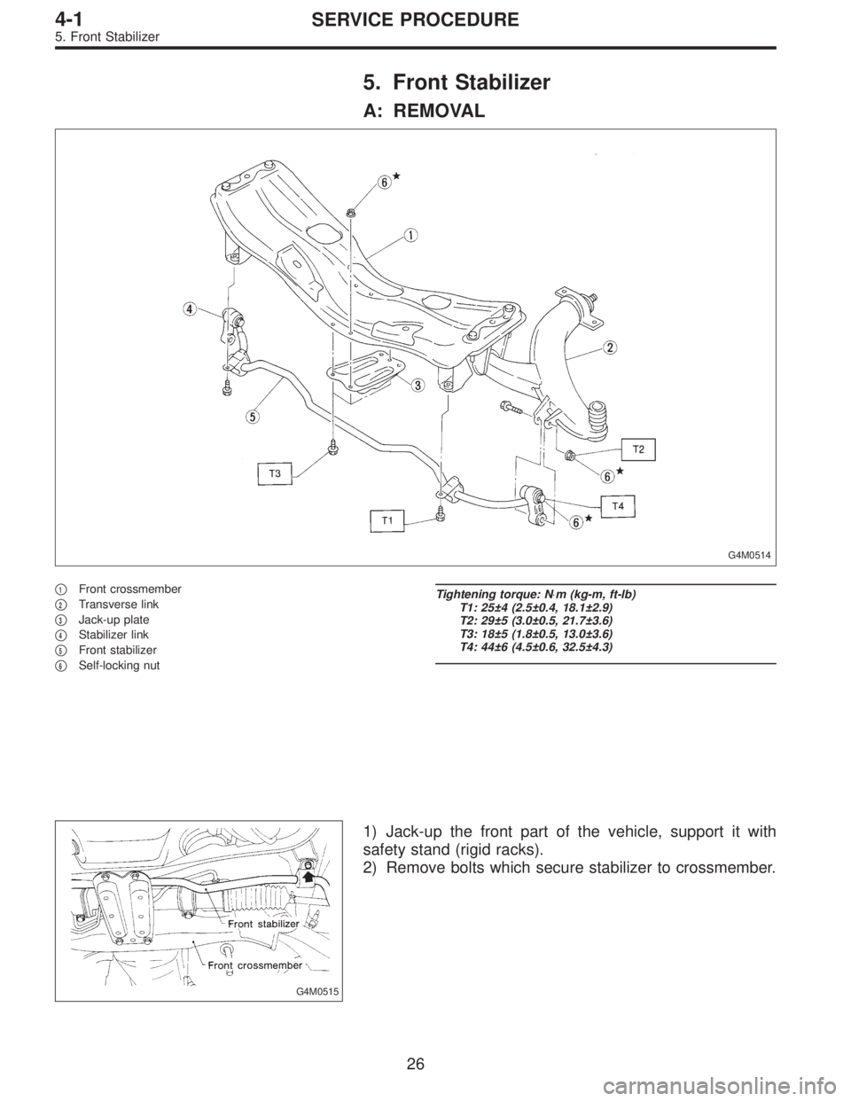
A: REMOVAL
G4M0514
�1Front crossmember
�
2Transverse link
�
3Jack-up plate
�
4Stabilizer link
�
5Front stabilizer
�
6Self-locking nut
Tightening torque: N⋅m (kg-m, ft-lb)
T1: 25±4 (2.5±0.4, 18.1±2.9)
T2: 29±5 (3.0±0.5, 21.7±3.6)
T3: 18±5 (1.8±0.5, 13.0±3.6)
T4: 44±6 (4.5±0.6, 32.5±4.3)
G4M0515
1) Jack-up the front part of the vehicle, support it with
safety stand (rigid racks).
2) Remove bolts which secure stabilizer to crossmember.
26
4-1SERVICE PROCEDURE
5. Front Stabilizer
Page 1028 of 2890
 Remove bolts which secure stabilizer link to front trans-
verse link.
4) Remove jack-up plate from lower part of crossmember.
B: INSPECTION
1) Check bushing for cracks, fatigue or damage.
2")
G4M0516
3) Remove bolts which secure stabilizer link to front trans-
verse link.
4) Remove jack-up plate from lower part of crossmember.
B: INSPECTION
1) Check bushing for cracks, fatigue or damage.
2) Check stabilizer link for deformities, cracks, or damage,
and bushing for protrusions from the hole of stabilizer link
and its play.
G4M0519
C: INSTALLATION
1) To install, reverse the removal procedure.
NOTE:
�Install bushing (on front crossmember side) while align-
ing it with paint mark on stabilizer.
�Ensure that bushing and stabilizer have the same iden-
tification colors when installing.
2) Always tighten rubber bushing location when wheels
are in full contact with the ground and vehicle is at curb
weight condition.
Tightening torque:
Jack-up plate to crossmember:
18±5 N⋅m (1.8±0.5 kg-m, 13.0±3.6 ft-lb)
Stabilizer link to front transverse link:
29±5 N⋅m (3.0±0.5 kg-m, 21.7±3.6 ft-lb)
Stabilizer to crossmember:
25±4 N⋅m (2.5±0.4 kg-m, 18.1±2.9 ft-lb)
27
4-1SERVICE PROCEDURE
5. Front Stabilizer
Page 1029 of 2890
 Disconnect ground cable from battery.
2) Loosen front wheel nuts.
3) Lift-up vehicle, and remove front tires and wheels.
4) Remove both stabilizer and jack-u")
G4M0520
6. Front Crossmember
A: REMOVAL
1) Disconnect ground cable from battery.
2) Loosen front wheel nuts.
3) Lift-up vehicle, and remove front tires and wheels.
4) Remove both stabilizer and jack-up plate.
5) Disconnect tie-rod end from housing.
6) Remove front exhaust pipe.
G4M0521
7) Remove front transverse link from front crossmember
and body.
8) Remove nuts attaching engine mount cushion rubber to
crossmember.
9) Remove self-locking nuts connecting steering U/J and
pinion shaft.
10) Lift engine by approx. 10 mm (0.39 in) by using chain
block.
11) Support crossmember with a jack, remove nuts secur-
ing crossmember to body and lower crossmember gradu-
ally along with steering gearbox.
CAUTION:
When removing crossmember downward, be careful
that tie-rod end does not interfere with DOJ boot.
B: INSTALLATION
1) Installation is in the reverse order of removal proce-
dures.
CAUTION:
Always tighten rubber bushing when wheels are in full
contact with the ground and vehicle is at curb weight
condition.
Tightening torque:
Transverse link bushing to crossmember:
98±15 N⋅m (10.0±1.5 kg-m, 72±11 ft-lb)
Stabilizer to bushing:
25±4 N⋅m (2.5±0.4 kg-m, 18.1±2.9 ft-lb)
Tie-rod end to housing:
27.0±2.5 N⋅m (2.75±0.25 kg-m, 19.9±1.8 ft-lb)
Front cushion rubber to crossmember:
69±15 N⋅m (7.0±1.5 kg-m, 51±11 ft-lb)
Universal joint to pinion shaft:
24±3 N⋅m (2.4±0.3 kg-m, 17.4±2.2 ft-lb)
Crossmember to body:
98±15 N⋅m (10.0±1.5 kg-m, 72±11 ft-lb)
2) Purge air from power steering system.
NOTE:
Check wheel alignment and adjust if necessary.
28
4-1SERVICE PROCEDURE
6. Front Crossmember
Page 1030 of 2890
7. Rear Trailing Link
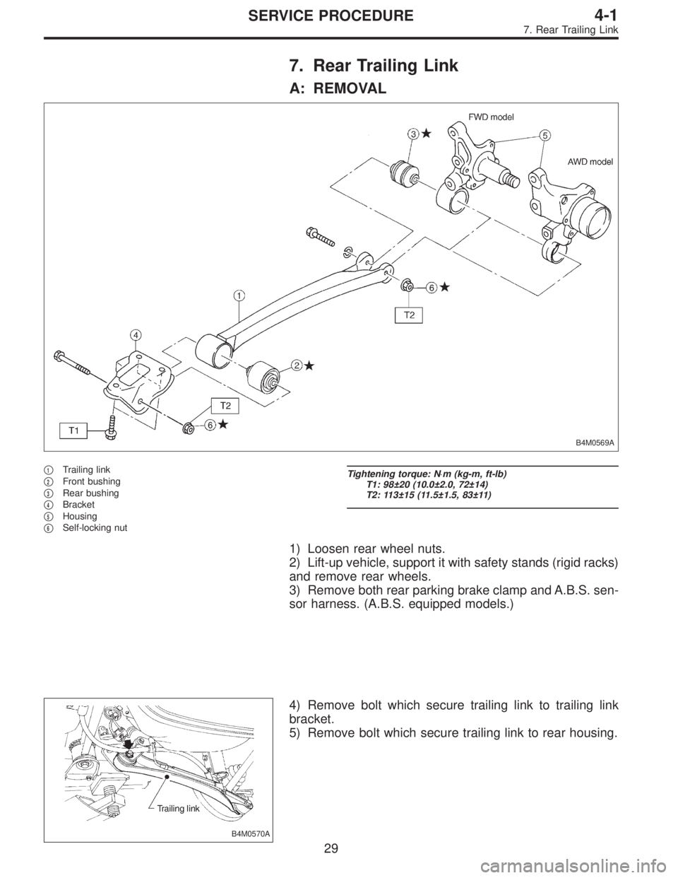
A: REMOVAL
B4M0569A
�1Trailing link
�
2Front bushing
�
3Rear bushing
�
4Bracket
�
5Housing
�
6Self-locking nut
Tightening torque: N⋅m (kg-m, ft-lb)
T1: 98±20 (10.0±2.0, 72±14)
T2: 113±15 (11.5±1.5, 83±11)
1) Loosen rear wheel nuts.
2) Lift-up vehicle, support it with safety stands (rigid racks)
and remove rear wheels.
3) Remove both rear parking brake clamp and A.B.S. sen-
sor harness. (A.B.S. equipped models.)
B4M0570A
4) Remove bolt which secure trailing link to trailing link
bracket.
5) Remove bolt which secure trailing link to rear housing.
29
4-1SERVICE PROCEDURE
7. Rear Trailing Link
Page 1036 of 2890
 Loosen wheel nuts. Lift-up vehicle and remove wheel.
2) Remove rear exhaust pipe and muffler.
3) Remove stabilizer link from rear lateral link.
4) Scribe an aligning mark on ad")
G4M0529
1. FWD MODEL
1) Loosen wheel nuts. Lift-up vehicle and remove wheel.
2) Remove rear exhaust pipe and muffler.
3) Remove stabilizer link from rear lateral link.
4) Scribe an aligning mark on adjusting bolt, adjusting
wheel and crossmember.
5) Remove bolts securing lateral links to housing.
6) Turn cap (lateral link) counterclockwise until it contacts
stopper, then remove cap.
7) While holding adjusting bolt’s head with a wrench,
loosen self-locking nut.
CAUTION:
Always loosen self-locking nut before turning adjust-
ing bolt.
8) Lateral link removal
(1) Left lateral links
Remove adjusting bolt and front and rear lateral links.
(2) Right lateral links
Support crossmember with transmission jack.
Remove bolts securing crossmember to vehicle body.
Lower transmission jack until adjusting bolt can be
removed. Remove adjusting bolt, front and rear lateral
links.
2. AWD MODEL
1) Loosen wheel nuts. Lift-up vehicle and remove wheel.
2) Remove stabilizers link from lateral link.
3) Remove A.B.S. sensor harness from trailing link.
(A.B.S. equipped models.)
B4M0573A
4) Remove bolt securing trailing link to housing.
5) Remove DOJ from differential.
6) Scribe an alignment mark on rear lateral link adjusting
bolt and crossmember.
7) Remove bolt securing lateral link to housing.
8) Remove bolts securing front and rear lateral links to
crossmember, detach lateral links.
CAUTION:
To loosen adjusting bolt, always loosen nut while hold-
ing the head of adjusting bolt.
35
4-1SERVICE PROCEDURE
8. Lateral Link
Page 1041 of 2890
9. Rear Strut
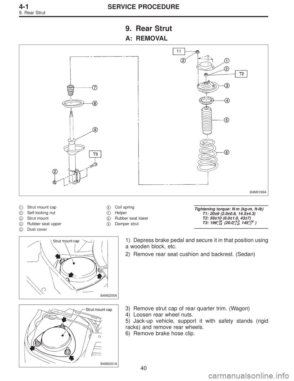
A: REMOVAL
B4M0199A
�1Strut mount cap
�
2Self-locking nut
�
3Strut mount
�
4Rubber seat upper
�
5Dust cover�
6Coil spring
�
7Helper
�
8Rubber seat lower
�
9Damper strut
Tightening torque: N⋅m (kg-m, ft-lb)
T1: 20±6 (2.0±0.6, 14.5±4.3)
T2: 59±10 (6.0±1.0, 43±7)
T3: 196
+39
�10(20.0+4.0
�1.0, 145+29
�7)
B4M0200A
1) Depress brake pedal and secure it in that position using
a wooden block, etc.
2) Remove rear seat cushion and backrest. (Sedan)
B4M0201A
3) Remove strut cap of rear quarter trim. (Wagon)
4) Loosen rear wheel nuts.
5) Jack-up vehicle, support it with safety stands (rigid
racks) and remove rear wheels.
6) Remove brake hose clip.
40
4-1SERVICE PROCEDURE
9. Rear Strut
Page 1042 of 2890
G4M0538
7) Models equipped with rear disc brakes:
Remove union bolt from brake caliper.
8) Models equipped with rear drum brakes:
Disconnect brake hose from brake pipe from strut, and
disconnect brake pipe from dram brake.
G4M0539
9) Remove bolts which secure rear strut to housing.
10) Remove nuts securing strut mount to body.
11) Remove strut mount cap.
B: DISASSEMBLY
For disassembly of rear strut, refer to procedures outlined
under front strut as a guide.
C: INSPECTION
Refer to Front Strut 4-1 [W4C0] as a guide for inspection
procedures.
G4M0540
D: ASSEMBLY
Refer to Front Strut 4-1 [W4D0] as a guide for assembly
procedures.
CAUTION:
�Install rear strut with “FWD” or “4WD” mark on strut
mount facing outside of vehicle body.
�Insert the protrusion of lower rubber seat into the
strut spring seat hole.
41
4-1SERVICE PROCEDURE
9. Rear Strut
Page 1043 of 2890
 Install strut mount cap.
2) Tighten self-locking nut used to secure strut mount to
vehicle body.
CAUTION:
Use a new self-locking nut.
NOTE:
Tighten strut mount and cap as a unit.
Ti")
E: INSTALLATION
1) Install strut mount cap.
2) Tighten self-locking nut used to secure strut mount to
vehicle body.
CAUTION:
Use a new self-locking nut.
NOTE:
Tighten strut mount and cap as a unit.
Tightening torque:
20±6 N⋅m (2.0±0.6 kg-m, 14.5±4.3 ft-lb)
3) Tighten bolts securing rear strut to housing.
Tightening torque:
196
+39
�10N⋅m (20.0+4.0
�1.0kg-m, 145+29
�7ft-lb)
CAUTION:
Use a new self-locking nut.
4) Models with rear disc brakes:
Tighten brake hose union bolt on brake caliper.
Tightening torque:
18±3 N⋅m (1.8±0.3 kg-m, 13.0±2.2 ft-lb)
Models with rear drum brakes:
Connect brake hose to brake pipe.
Tightening torque:
15
+3
�2N⋅m (1.5+0.3
�0.2kg-m, 10.8+2.2
�1.4ft-lb)
5) Insert brake hose clip between brake hose and lower
side of strut.
CAUTION:
�Check that hose clip is positioned properly.
�Check brake hose for twisting, or excessive tension.
�Models equipped with A.B.S.:
Do not subject A.B.S. sensor harness to excessive ten-
sion.
6) Be sure to bleed air from brake system.
7) Lower vehicle and tighten wheel nut.
Tightening torque:
88±10 N⋅m (9±1 kg-m, 65±7 ft-lb)
8) Sedan:
Install rear seat backrest and rear seat cushion.
Wagon:
Install strut cap of rear quarter trim.
NOTE:
Check wheel alignment and adjust if necessary.
42
4-1SERVICE PROCEDURE
9. Rear Strut
 Models equipped with rear disc brakes:
Remove union bolt from brake caliper.
8) Models equipped with rear drum brakes:
Disconnect brake hose from brake pipe from strut, and
disconnect brake")