Page 934 of 2890
G3M0484
9) Install the one-way clutch (1-2) and plate, and secure
with the snap ring.
NOTE:
Set the inner race. Make sure that the forward clutch is free
in the clockwise direction and locked in the counterclock-
wise direction, as viewed from the front of the vehicle.
G3M0911
12. One-way Clutch Outer Race
A: DISASSEMBLY
Remove the snap ring. Then remove the one-way clutch
(3-4).
B: INSPECTION
Check the sliding surface and one-way clutch (3-4) for any
harmful cuts, damage, or other faults.
G3M0486
C: ASSEMBLY
1) Assemble the one-way clutch (3-4), and secure with the
snap ring.
NOTE:
Pay attention to the orientation of the one-way clutch (3-4).
2) Assemble the rear internal gear, and secure the outer
race. Make sure that the internal gear is locked in the
clockwise direction, and free to rotate in the counterclock-
wise direction.
105
3-2SERVICE PROCEDURE
11. Forward Clutch Drum - 12. One-Way Clutch Outer Race
Page 935 of 2890

�
5Lathe cut seal ring
�
6O-ring
�
7Band servo retainer
�
8O-ring
�
9Spring
�
10Retainer")
B3M0407A
13. Servo Piston
�1Band servo piston stem
�
2Spring
�
3Lathe cut seal ring
�
4Band servo piston (1-2)
�
5Lathe cut seal ring
�
6O-ring
�
7Band servo retainer
�
8O-ring
�
9Spring
�
10Retainer
�
11Snap ring
�
12Lathe cut seal ring
�
13Band servo piston (3-4)
�
14O-ring
�
15O.D. servo retainer
�
16Snap ring
�
17Washer
A: DISASSEMBLY
1) Remove the spring.
2) Remove the band servo piston (3-4).
3) While compressing the retainer from above, remove the
snap ring. Then remove the retainer, spring and stem.
4) Take out the band servo piston (1-2).
B: INSPECTION
1) Check each component for harmful cuts, damage, or
other faults.
2) Check the O-ring and lathe cut ring for damage.
C: ASSEMBLY
1) Install the band servo piston (1-2) to the retainer, and
insert the stem.
2) Put the spring and retainer on the piston. Fit the snap
ring securely while compressing the spring.
3) Install the band servo piston (3-4).
4) Install the spring securely to the band servo piston
(1-2).
CAUTION:
�Many different O-rings and lathe cut rings are used.
Be careful not to confuse them when installing.
�Be careful not to damage O-rings and lathe cut
rings.
106
3-2SERVICE PROCEDURE
13. Servo Piston
Page 936 of 2890
G3M0488
14. Differential Case Assembly
A: DISASSEMBLY
1) Using a press and ST, remove the taper roller bearing.
ST 498077000 REMOVER
CAUTION:
Be careful not to damage the speedometer drive gear.
G3M0489
2) Secure the case in a vise and remove the crown gear
tightening bolts, then separate the crown gear, case (RH)
and case (LH).
G3M0490
3) Pull out the straight pin and shaft, and remove the dif-
ferential bevel gear, washer, and differential bevel pinion.
B: INSPECTION
Check each component for harmful cuts, damage and
other faults.
G3M0490
C: ASSEMBLY
1) Install the washer, differential bevel gear and differen-
tial bevel pinion in the differential case (RH). Insert the
pinion shaft, and fit the straight pin.
NOTE:
Install straight pin from reverse direction.
107
3-2SERVICE PROCEDURE
14. Differential Case Assembly
Page 937 of 2890
G3M0489
2) Install the washer and differential bevel gear to the dif-
ferential case (LH). Then put the case over the differential
case (RH), and connect both cases.
3) Install the crown gear and secure by tightening the bolt.
Standard tightening torque:
62±5 N⋅m (6.3±0.5 kg-m, 45.6±3.6 ft-lb)
G3M0491
4) Measurement of backlash (Selection of washer)
Measure the gear backlash with ST1 and ST2, and insert
ST2 through the access window of the case.
ST1 498247001 MAGNET BASE
ST2 498247100 DIAL GAUGE
Standard value:
0.13—0.18 mm (0.0051—0.0071 in)
NOTE:
Measure the backlash by applying a pinion tooth between
two bevel gear teeth.
G3M0492
5) Install the speedometer drive gear. Then force-fit the
taper roller bearing with a press and ST.
ST 398487700 DRIFT
CAUTION:
Be sure to position correctly the locking end of the
speedometer drive gear.
108
3-2SERVICE PROCEDURE
14. Differential Case Assembly
Page 940 of 2890
G3M0501
3) Install the driven plates, drive plates, and pressure
plate, and secure with a snap ring with ST1, ST2 and a
press.
ST1 398673600 COMPRESSOR
ST2 498627000 SEAT
G3M0502
4) Apply compressed air to see if the assembled parts
move smoothly.
G3M0503
5) Check the clearance.
Standard value:
0.2—0.6 mm (0.008—0.024 in)
Allowable limit:
1.6 mm (0.063 in)
If the clearance is not within the specified range, select a
proper pressure plate.
NOTE:
Before measuring clearance, place the same thickness of
shim on both sides to prevent pressure plate from tilting.
�Available pressure platesPart No. Thickness mm (in)
31593AA151
31593AA161
31593AA171
31593AA1813.3 (0.130)
3.7 (0.146)
4.1 (0.161)
4.5 (0.177)
G3M0505
6) Press-fit the ball bearing with ST.
ST 899580100 INSTALLER
111
3-2SERVICE PROCEDURE
15. Transfer Clutch
Page 976 of 2890
G3M0042
(5) Remove the bolts which secure the trailing link to
the rear housing.
G3M0043
(6) Remove the bolts which secure the front and rear
lateral link to the rear housing.
G3M1020
(7) Remove crossmember reinforcement lower (AWD
Sedan only).
(8) Remove the DOJ from the rear differential by using
ST.
ST 208099PA100 DRIVE SHAFT REMOVER
G3M1021
CAUTION:
When removing the DOJ from the rear differential, fit
tire lever to the bolt as shown in figure so as not to
damage the side bearing retainer.
G3M1022
9) Secure rear drive shaft to rear crossmember using wire.
17
3-4SERVICE PROCEDURE
2. Rear Differential
Page 979 of 2890
G3M0053
11) Remove heat sealed cover.
12) Remove clamps and bracket of parking brake cable.
13) Remove crossmember reinforcement lower (AWD
Sedan only).
G3M1020
14) Remove DOJ of rear drive shaft from rear differential
using ST.
ST 28099PA100 DRIVE SHAFT REMOVER
G3M1022
15) Secure rear drive shaft to rear crossmember using
wire.
G3M0054
16) Remove lower differential bracket.
G3M0055
17) Support rear differential with transmission jack.
20
3-4SERVICE PROCEDURE
2. Rear Differential
Page 980 of 2890
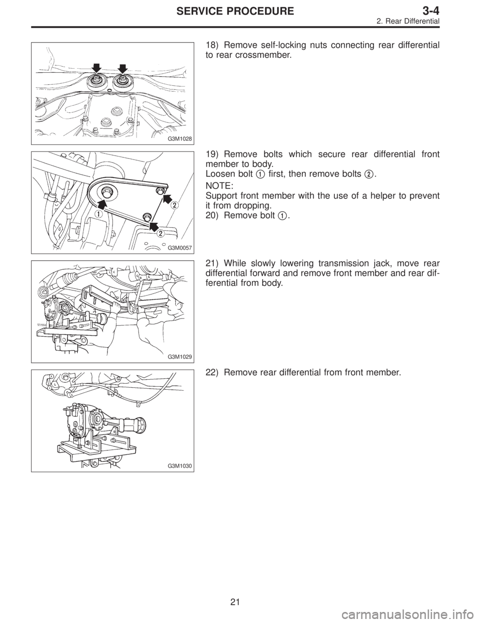
G3M1028
18) Remove self-locking nuts connecting rear differential
to rear crossmember.
G3M0057
19) Remove bolts which secure rear differential front
member to body.
Loosen bolt�
1first, then remove bolts�2.
NOTE:
Support front member with the use of a helper to prevent
it from dropping.
20) Remove bolt�
1.
G3M1029
21) While slowly lowering transmission jack, move rear
differential forward and remove front member and rear dif-
ferential from body.
G3M1030
22) Remove rear differential from front member.
21
3-4SERVICE PROCEDURE
2. Rear Differential
 Install the one-way clutch (1-2) and plate, and secure
with the snap ring.
NOTE:
Set the inner race. Make sure that the forward clutch is free
in the clockwise direction and locked in the c")
 Using a press and ST, remove the taper roller bearing.
ST 498077000 REMOVER
CAUTION:
Be careful not to damage the speedometer drive gear.
G3M04")
 Install the washer and differential bevel gear to the dif-
ferential case (LH). Then put the case over the differential
case (RH), and connect both cases.
3) Install the crown gear and secu")
 Install the driven plates, drive plates, and pressure
plate, and secure with a snap ring with ST1, ST2 and a
press.
ST1 398673600 COMPRESSOR
ST2 498627000 SEAT
G3M0502
4) Apply compressed a")
 Remove the bolts which secure the trailing link to
the rear housing.
G3M0043
(6) Remove the bolts which secure the front and rear
lateral link to the rear housing.
G3M1020
(7) Remove cross")
 Remove heat sealed cover.
12) Remove clamps and bracket of parking brake cable.
13) Remove crossmember reinforcement lower (AWD
Sedan only).
G3M1020
14) Remove DOJ of rear drive shaft from")