Page 818 of 2890
 Drive ball bearing�1onto the rear section of transmis-
sion main shaft using ST1, ST2 and a press.
ST1 899714110 REMOVER
ST2 499877000 RACE 4-5 INSTALLER
B3M0091A
6) Using the same tools as")
G3M0650
5) Drive ball bearing�1onto the rear section of transmis-
sion main shaft using ST1, ST2 and a press.
ST1 899714110 REMOVER
ST2 499877000 RACE 4-5 INSTALLER
B3M0091A
6) Using the same tools as in step 5) above, install the
following parts onto the rear section of transmission main
shaft.
�5th gear thrust washer
NOTE:
Face thrust washer in the correct direction.
�
c: Face this surface to 5th gear side.
ST1 899714110 REMOVER
ST2 499877000 RACE 4-5 INSTALLER
�5th needle bearing race
B3M0092A
7) Install the following parts to the rear section of transmis-
sion main shaft.
�Needle bearing (32 x 36 x 25.7)
�5th drive gear
�Baulk ring
�Sleeve�
Aand hub assembly
�Insert stopper plate�
B
�Lock washer�C(22x38x2)
�Tighten lock nuts�
D(22 x 13) to the specified torque
using ST1 and ST2.
ST1 499987003 SOCKET WRENCH (35)
ST2 498937000 TRANSMISSION HOLDER
NOTE:
�Align groove�
Ein baulk ring with shifting insert.
�Be sure to fit pawl�
Fof insert stopper plate into 4 mm
(0.16 in) dia. hole in the boss section of synchronizer hub.
�Secure lock nuts in two places after tightening.
Tightening torque:
118±6 N⋅m (12.0±0.6 kg-m, 86.8±4.3 ft-lb)
62
3-1SERVICE PROCEDURE
7. Main Shaft Assembly
Page 855 of 2890
G3M0293
(4) Check if there is continuity at equal points when the
select lever is turned 1.5°in both directions from the N
range.
If there is continuity in one direction and the continuity
in the other or if there is continuity at unequal points,
adjust the inhibitor switch.
G3M0294
(1) Loosen the three inhibitor switch securing bolts.
(2) Shift the select lever to the N range.
(3) Insert ST as vertical as possible into the holes in
the inhibitor switch lever and switch body.
ST 499267300 STOPPER PIN
(4) Tighten the three inhibitor switch bolts.
Tightening torque:
3.4±0.5 N⋅m (0.35±0.05 kg-m, 2.5±0.4 ft-lb)
(5) Repeat the above checks. If the inhibitor switch is
determined to be“faulty”, replace it.
G3M0295
3. SENSOR (IN TRANSMISSION)
Check each sensor, solenoid and ground system for short
circuits.
29
3-2SERVICE PROCEDURE
2. On-Car Services
Page 859 of 2890
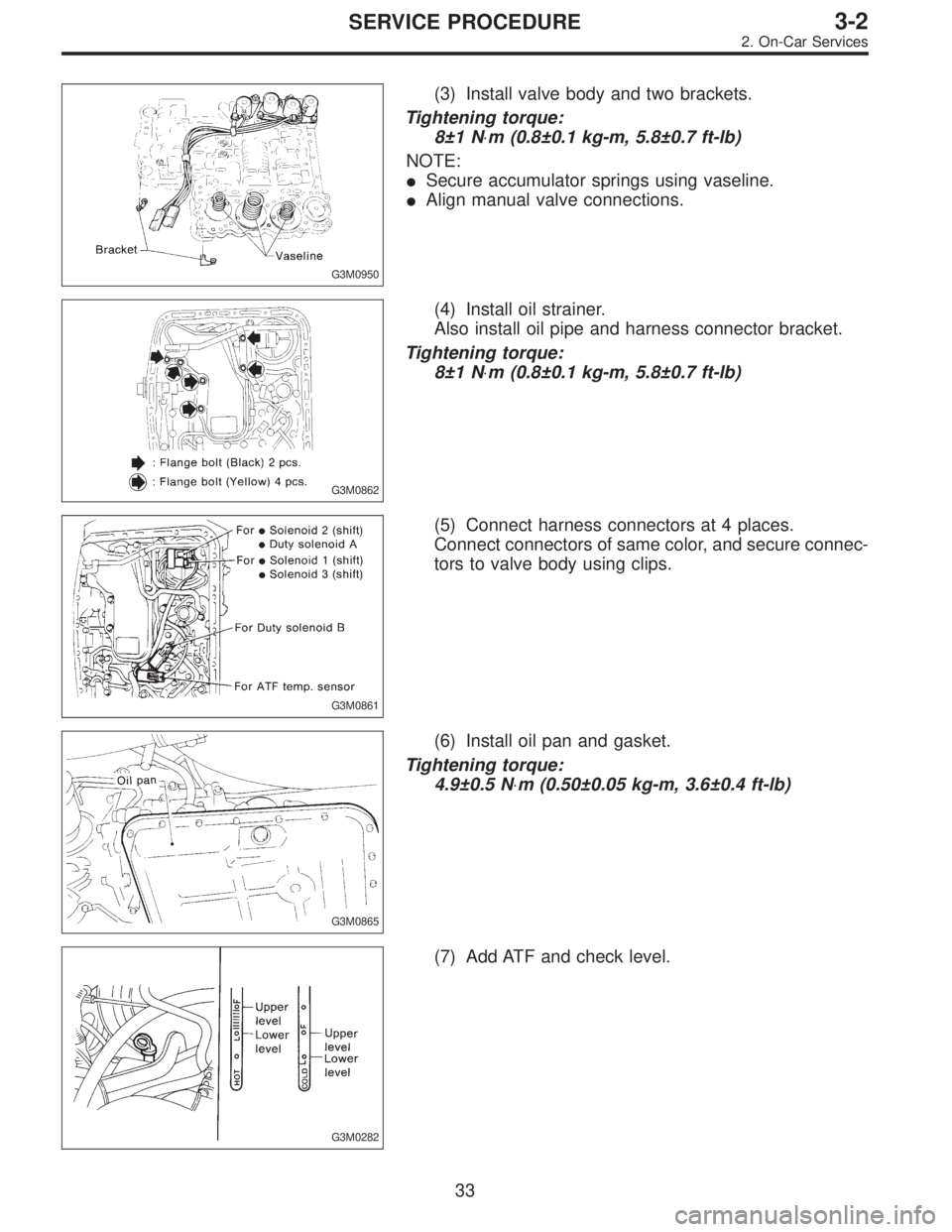
G3M0950
(3) Install valve body and two brackets.
Tightening torque:
8±1 N⋅m (0.8±0.1 kg-m, 5.8±0.7 ft-lb)
NOTE:
�Secure accumulator springs using vaseline.
�Align manual valve connections.
G3M0862
(4) Install oil strainer.
Also install oil pipe and harness connector bracket.
Tightening torque:
8±1 N⋅m (0.8±0.1 kg-m, 5.8±0.7 ft-lb)
G3M0861
(5) Connect harness connectors at 4 places.
Connect connectors of same color, and secure connec-
tors to valve body using clips.
G3M0865
(6) Install oil pan and gasket.
Tightening torque:
4.9±0.5 N⋅m (0.50±0.05 kg-m, 3.6±0.4 ft-lb)
G3M0282
(7) Add ATF and check level.
33
3-2SERVICE PROCEDURE
2. On-Car Services
Page 861 of 2890
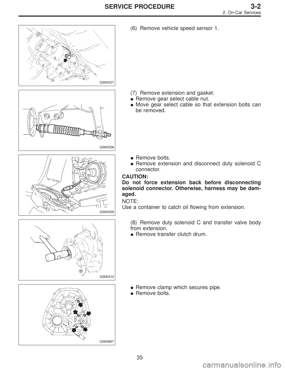
G3M0307
(6) Remove vehicle speed sensor 1.
G3M0308
(7) Remove extension and gasket.
�Remove gear select cable nut.
�Move gear select cable so that extension bolts can
be removed.
G3M0309
�Remove bolts.
�Remove extension and disconnect duty solenoid C
connector.
CAUTION:
Do not force extension back before disconnecting
solenoid connector. Otherwise, harness may be dam-
aged.
NOTE:
Use a container to catch oil flowing from extension.
G3M0310
(8) Remove duty solenoid C and transfer valve body
from extension.
�Remove transfer clutch drum.
G3M0867
�Remove clamp which secures pipe.
�Remove bolts.
35
3-2SERVICE PROCEDURE
2. On-Car Services
Page 885 of 2890
 Check the appearance of each component and clean.
CAUTION:
Make sure each part is free of harmful cuts, damage
and other")
B: ASSEMBLY OF OVERALL TRANSMISSION
1. TORQUE CONVERTER CLUTCH CASE SECTION
1) Check the appearance of each component and clean.
CAUTION:
Make sure each part is free of harmful cuts, damage
and other faults.
G3M0377
2) Install the washer and snap ring to the speedometer
shaft with ST, and set the oil seal. Then force-fit the shaft
to the torque converter clutch case.
ST 499827000 PRESS
3) Install vehicle speed sensor 2.
CAUTION:
Use new vehicle speed sensor 2, if it has been
removed.
Tightening torque:
5.9±1.5 N⋅m (60±15 kg-cm, 52±13 in-lb)
G3M0378
4) Install the speedometer driven gear to the speedometer
shaft, and secure with a snap ring.
G3M0379
5) Force-fit the oil seal to the torque converter clutch case
with ST.
ST 398437700 DRIFT
G3M0380
6) Install the differential assembly to the case, paying spe-
cial attention not to damage the speedometer gears (drive
and driven) and the inside of the case (particularly, the dif-
ferential side retainer contact surface).
59
3-2SERVICE PROCEDURE
4. Overall Transmission
Page 887 of 2890
 Tighten four bolts to secure the roller bearing.
Tightening torque:
39±3 N⋅m (4.0±0.3 kg-m, 28.9±2.2 ft-lb)
G3M0883
(3) Install the oil pump housing assembly to the torque
converter c")
G3M0383
(2) Tighten four bolts to secure the roller bearing.
Tightening torque:
39±3 N⋅m (4.0±0.3 kg-m, 28.9±2.2 ft-lb)
G3M0883
(3) Install the oil pump housing assembly to the torque
converter clutch case, and secure evenly by tightening
four bolts.
Tightening torque:
41±3 N⋅m (4.2±0.3 kg-m, 30.4±2.2 ft-lb)
CAUTION:
�Thoroughly remove the liquid gasket from the case
mating surface beforehand.
�Use an old gasket or an aluminum washer so as not
to damage the mating surface of the housing.
G3M0384
(4) Rotate the drive pinion several times with ST1 and
ST2.
ST1 498937100 HOLDER
ST2 499787100 WRENCH
G3M0884
(5) Tighten the LH retainer until contact is felt while
rotating the shaft. Then loosen the RH retainer. Keep
tightening the LH retainer and loosening the RH
retainer until the pinion shaft can no longer be turned.
This is the“zero”state.
G3M0885
(6) After the“zero”state is established, back off the LH
retainer 3 notches and secure it with the lock plate.
Then back off the RH retainer and retighten until it
stops. Repeat this procedure several times. Tighten the
RH retainer 1-3/4 notches further. This sets the preload.
Finally, secure the retainer with its lock plate.
NOTE:
Turning the retainer by one tooth changes the backlash
about 0.05 mm (0.0020 in).
61
3-2SERVICE PROCEDURE
4. Overall Transmission
Page 890 of 2890
 If tooth contact is correct, mark the retainer position
and loosen it. After fitting the O-ring, screw in the
retainer to the marked position. Then tighten the lock
plate to the specified")
G3M0885
(9) If tooth contact is correct, mark the retainer position
and loosen it. After fitting the O-ring, screw in the
retainer to the marked position. Then tighten the lock
plate to the specified torque.
Tightening torque:
25±2 N⋅m (2.5±0.2 kg-m, 18.1±1.4 ft-lb)
G3M0370
12) Install the seal pipe to the torque converter clutch
case.
CAUTION:
Be sure to use a new seal pipe.
G3M0390
13) Install two oil seals to the oil seal retainer with ST.
ST 499247300 INSTALLER
CAUTION:
�Always discard old oil seals, and install new ones.
�Pay attention to the orientation of the oil seals.
G3M0886
14) Attach the O-ring to the oil seal retainer with vaseline.
Install the seal to the oil pump housing bore.
CAUTION:
Always discard old O-rings and install new ones.
G3M0392
15) Install the oil seal retainer taking care not to damage
the oil seal lips. Then secure with three bolts.
NOTE:
Make sure the O-ring is fitted correctly in position.
Tightening torque:
7±1 N⋅m (0.7±0.1 kg-m, 5.1±0.7 ft-lb)
64
3-2SERVICE PROCEDURE
4. Overall Transmission
Page 891 of 2890
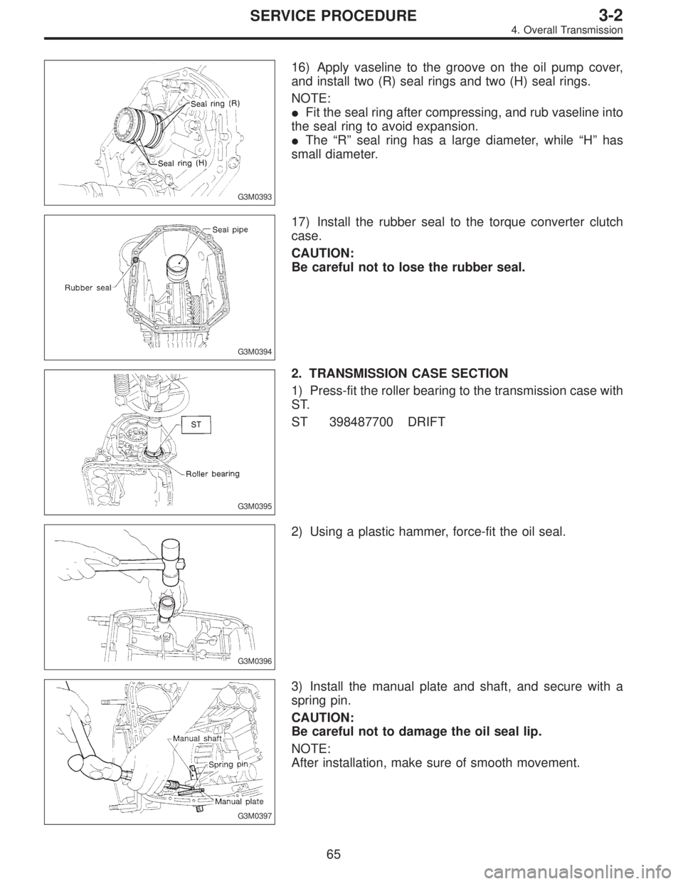
G3M0393
16) Apply vaseline to the groove on the oil pump cover,
and install two (R) seal rings and two (H) seal rings.
NOTE:
�Fit the seal ring after compressing, and rub vaseline into
the seal ring to avoid expansion.
�The“R”seal ring has a large diameter, while“H”has
small diameter.
G3M0394
17) Install the rubber seal to the torque converter clutch
case.
CAUTION:
Be careful not to lose the rubber seal.
G3M0395
2. TRANSMISSION CASE SECTION
1) Press-fit the roller bearing to the transmission case with
ST.
ST 398487700 DRIFT
G3M0396
2) Using a plastic hammer, force-fit the oil seal.
G3M0397
3) Install the manual plate and shaft, and secure with a
spring pin.
CAUTION:
Be careful not to damage the oil seal lip.
NOTE:
After installation, make sure of smooth movement.
65
3-2SERVICE PROCEDURE
4. Overall Transmission
 Check if there is continuity at equal points when the
select lever is turned 1.5°in both directions from the N
range.
If there is continuity in one direction and the continuity
in the oth")