Page 702 of 2890
 Check the routing of clutch cable for smoothness.
2) Excessive tightnes")
1. General
A: PRECAUTION
When servicing clutch system, pay attention to the follow-
ing items.
1. MECHANICAL APPLICATION TYPE
1) Check the routing of clutch cable for smoothness.
2) Excessive tightness or looseness of clutch cable have
a bad influence upon the cable durability.
3) Apply grease sufficiently to the connecting portion of
clutch pedal.
4) Apply grease sufficiently to the release lever portion.
5) Position clutch cable through the center of toe board
hole and route it smoothly. Adjustment is done by moving
the outer cable.
6) Make sure not to let the clutch chatter when starting
forward or rearward. If clutch chattering occurs, readjust so
that the bend of clutch outer cable becomes flatter.
G2M0234
2. On-Car Service
1. MECHANICAL APPLICATION TYPE
1) Remove release lever return spring from lever (Models
without hill holder only).
2) Adjust spherical nut so that the play is within the speci-
fied value at the lever end (center of spherical nut).
CAUTION:
Take care not to twist the cable during adjustment
Play: 3 — 4 mm (0.12 — 0.16 in)
Full stroke: 24 — 26 mm (0.94 — 1.02 in)
G2M0235
3) Upon completion of adjustment, securely lock spherical
nut with lock nut.
Install return spring on lever (Models without hill holder
only).
NOTE:
Hook the long hook side of the return spring with the lever
(Models without hill holder only).
4
2-10SERVICE PROCEDURE
1. General - 2. On-Car Service
Page 703 of 2890
 Check the routing of clutch cable for smoothness.
2) Excessive tightnes")
1. General
A: PRECAUTION
When servicing clutch system, pay attention to the follow-
ing items.
1. MECHANICAL APPLICATION TYPE
1) Check the routing of clutch cable for smoothness.
2) Excessive tightness or looseness of clutch cable have
a bad influence upon the cable durability.
3) Apply grease sufficiently to the connecting portion of
clutch pedal.
4) Apply grease sufficiently to the release lever portion.
5) Position clutch cable through the center of toe board
hole and route it smoothly. Adjustment is done by moving
the outer cable.
6) Make sure not to let the clutch chatter when starting
forward or rearward. If clutch chattering occurs, readjust so
that the bend of clutch outer cable becomes flatter.
G2M0234
2. On-Car Service
1. MECHANICAL APPLICATION TYPE
1) Remove release lever return spring from lever (Models
without hill holder only).
2) Adjust spherical nut so that the play is within the speci-
fied value at the lever end (center of spherical nut).
CAUTION:
Take care not to twist the cable during adjustment
Play: 3 — 4 mm (0.12 — 0.16 in)
Full stroke: 24 — 26 mm (0.94 — 1.02 in)
G2M0235
3) Upon completion of adjustment, securely lock spherical
nut with lock nut.
Install return spring on lever (Models without hill holder
only).
NOTE:
Hook the long hook side of the return spring with the lever
(Models without hill holder only).
4
2-10SERVICE PROCEDURE
1. General - 2. On-Car Service
Page 707 of 2890
 While pushing release lever�
3to pivot and twisting it to
both sides, fit retainer spring�
5onto the constricted portion
of pivot.
NOTE:
Confirm that retaine")
B2M0633A
1. MECHANICAL APPLICATION TYPE
1) While pushing release lever�
3to pivot and twisting it to
both sides, fit retainer spring�
5onto the constricted portion
of pivot.
NOTE:
Confirm that retainer spring is securely fitted by observing
it through the main case hole.
2) Install release bearing�
6and fasten it with two clips�2.
3) Install release lever seal�
4.
G2M0235
4) After remounting engine and transmission on body,
make adjustment of the clutch release lever end play.
CAUTION:
Take care not to twist the cable during adjustment.
5) Install release lever return spring (Models without hill
holder only).
NOTE:
Hook up the return spring to right side hole of the release
lever.
G2M0242
4. Clutch Disc and Cover
A: REMOVAL
1) Install ST on flywheel.
ST 498497100 CRANKSHAFT STOPPER
2) Remove clutch cover and clutch disc.
CAUTION:
�Take care not to allow oil on the clutch disc facing.
�Do not disassemble either clutch cover or clutch
disc.
G2M0243
3) Remove flywheel.
7
2-10SERVICE PROCEDURE
3. Release Bearing and Lever - 4. Clutch Disc and Cover
Page 708 of 2890
 While pushing release lever�
3to pivot and twisting it to
both sides, fit retainer spring�
5onto the constricted portion
of pivot.
NOTE:
Confirm that retaine")
B2M0633A
1. MECHANICAL APPLICATION TYPE
1) While pushing release lever�
3to pivot and twisting it to
both sides, fit retainer spring�
5onto the constricted portion
of pivot.
NOTE:
Confirm that retainer spring is securely fitted by observing
it through the main case hole.
2) Install release bearing�
6and fasten it with two clips�2.
3) Install release lever seal�
4.
G2M0235
4) After remounting engine and transmission on body,
make adjustment of the clutch release lever end play.
CAUTION:
Take care not to twist the cable during adjustment.
5) Install release lever return spring (Models without hill
holder only).
NOTE:
Hook up the return spring to right side hole of the release
lever.
G2M0242
4. Clutch Disc and Cover
A: REMOVAL
1) Install ST on flywheel.
ST 498497100 CRANKSHAFT STOPPER
2) Remove clutch cover and clutch disc.
CAUTION:
�Take care not to allow oil on the clutch disc facing.
�Do not disassemble either clutch cover or clutch
disc.
G2M0243
3) Remove flywheel.
7
2-10SERVICE PROCEDURE
3. Release Bearing and Lever - 4. Clutch Disc and Cover
Page 775 of 2890
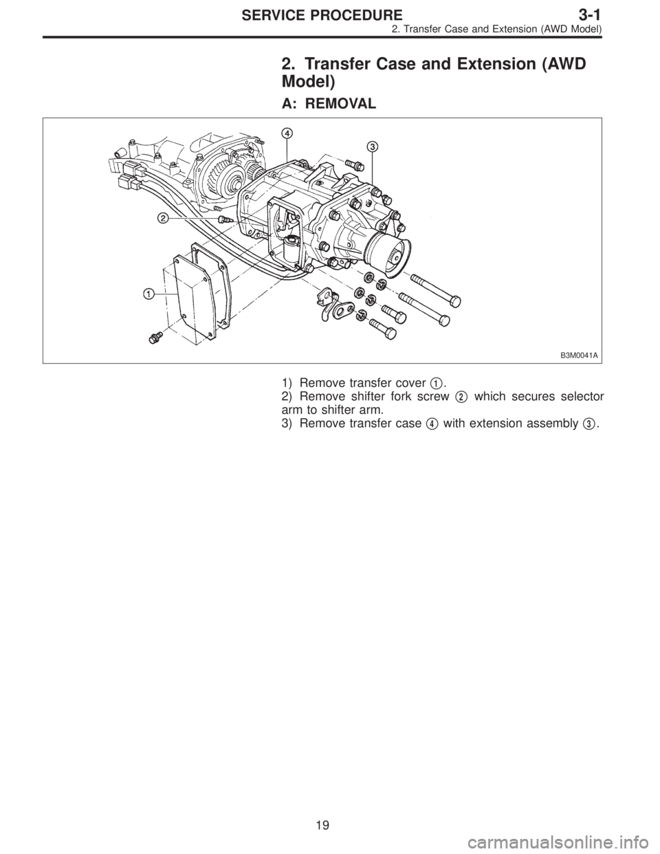
2. Transfer Case and Extension (AWD
Model)
A: REMOVAL
B3M0041A
1) Remove transfer cover�1.
2) Remove shifter fork screw�
2which secures selector
arm to shifter arm.
3) Remove transfer case�
4with extension assembly�3.
19
3-1SERVICE PROCEDURE
2. Transfer Case and Extension (AWD Model)
Page 784 of 2890

T1: 15.7±1.5 (1.6±0.15, 11.6±1.1)
T2: 19.6±1.5 (2.00±0.15, 14.5±1.1)
T3: 24.5±2.0 (2.50±0.20, 18.1±1.4)
1) Install transfer cas")
D: INSTALLATION
B3M0053A
Tightening torque: N⋅m (kg-m, ft-lb)
T1: 15.7±1.5 (1.6±0.15, 11.6±1.1)
T2: 19.6±1.5 (2.00±0.15, 14.5±1.1)
T3: 24.5±2.0 (2.50±0.20, 18.1±1.4)
1) Install transfer case�2with extension assembly�1.
2) Secure selector arm to shifter arm with shifter fork
screw�
3. Shifter arm should be caught by pawl of rod.
Selector arm must be engaged with reverse check sleeve
assembly.
3) Adjustment of neutral position
(1) Shift gear into 3rd gear position.
(2) Shifter arm turns lightly toward the 1st/2nd gear
side but heavily toward the reverse gear side because
of the function of the return spring, until arm contacts
the stopper.
(3) Make adjustment so that the heavy stroke (reverse
side) is a little more than the light stroke (1st/2nd side).
(4) To adjust, remove bolts holding reverse check
sleeve assembly�
4to the case, move sleeve assem-
bly outward, and place adjustment shim (0 to 1 ea.)
between sleeve assembly and case to adjust the clear-
ance.
28
3-1SERVICE PROCEDURE
2. Transfer Case and Extension (AWD Model)
Page 793 of 2890
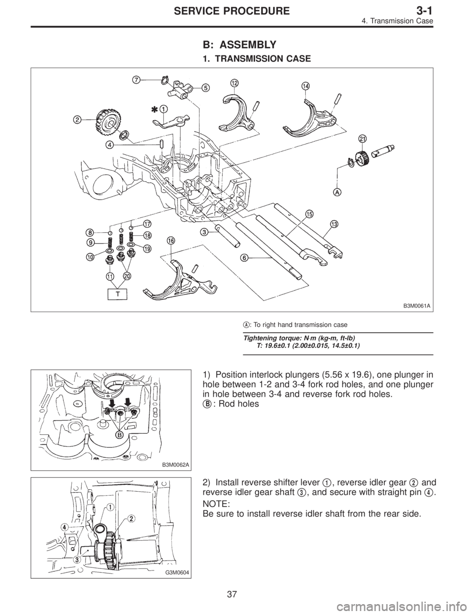
B: ASSEMBLY
1. TRANSMISSION CASE
B3M0061A
�A: To right hand transmission case
Tightening torque: N⋅m (kg-m, ft-lb)
T: 19.6±0.1 (2.00±0.015, 14.5±0.1)
B3M0062A
1) Position interlock plungers (5.56 x 19.6), one plunger in
hole between 1-2 and 3-4 fork rod holes, and one plunger
in hole between 3-4 and reverse fork rod holes.
�
B: Rod holes
G3M0604
2) Install reverse shifter lever�1, reverse idler gear�2and
reverse idler gear shaft�
3, and secure with straight pin�4.
NOTE:
Be sure to install reverse idler shaft from the rear side.
37
3-1SERVICE PROCEDURE
4. Transmission Case
Page 815 of 2890
G3M0640
10) Install ball bearing (29 x 74 x 38) on drive pinion shaft
with ST.
ST 499277100 INSTALLER
G3M0617
11) Position woodruff key in groove on the rear of drive
pinion shaft. Install 5th driven gear onto drive shaft using
ST and press.
ST 499277100 INSTALLER
CAUTION:
�Face 5th driven gear in the correct direction.
�Be careful not to dislocate woodruff key while
installing 5th gear.
B3M0353A
G3M0628
12) Install lock washer and tighten lock nut to the specified
torque using ST1 and ST2.
ST1 499987100 or 499987003 or 899984103 SOCKET
WRENCH (35)
ST2 899884100 HOLDER
CAUTION:
�Discard old lock nuts, replace with new ones.
�Secure lock nut in four places.
Tightening torque:
11 2—124 N⋅m (11.4—12.6 kg-m, 82—91 ft-lb)
59
3-1SERVICE PROCEDURE
6. Drive Pinion Assembly (FWD Model)
 Install ball bearing (29 x 74 x 38) on drive pinion shaft
with ST.
ST 499277100 INSTALLER
G3M0617
11) Position woodruff key in groove on the rear of drive
pinion shaft. Install 5th driven")