Page 255 of 2890
ON-BOARD
DIAGNOSTICS
II
SYSTEM
[TloBVi]
2-7
10
.
Diagnostics
Chart
with
Trouble
Code
Test
mode
connector
B2M04328
10BV1
I
CHECK
FUEL
TANK
PRESSURE
CONTROL
SOLENOID
VALVE
.
1)
Turn
ignition
switch
to
OFF
.
2)
Connect
test
mode
connector
.
3)
Turn
ignition
switch
to
ON
.
CHECK
:
Does
fuel
tank
pressure
control
solenoid
valve
produce
operating
sound?
NOTE
:
Fuel
tank
pressure
control
solenoid
valve
operation
check
can
also
be
executed
using
Subaru
Select
Monitor
(Func-
tion
mode
:
FD07)
.
For
the
procedure,
refer
to
"COMPUL-
SORY
VALVE
OPERATION
CHECK
MODE"
2-7
[T3F0]*4
.
vES
:
Check
evaporative
emission
control
system
.
<
Ref
.
to
2-7
[T10BQ0]
.*7
>
No
:
Replace
fuel
tank
pressure
control
solenoid
valve
.
45
Page 256 of 2890
![SUBARU LEGACY 1996 Service Repair Manual 2_7
[T10BW0]
ON-BOARD
DIAGNOSTICS
II
SYSTEM
10
.
Diagnostics
Chart
with
Trouble
Code
OBD
(FBI)
P1402
<FLVL>
H2M1411
BW
:
DTC
P1402
-
FUEL
LEVEL
SENSOR
CIRCUIT
MALFUNCTION
(FLVL)
-
DTC
DETECTIN](/manual-img/17/57433/w960_57433-255.png "SUBARU LEGACY 1996 Service Repair Manual 2_7
[T10BW0]
ON-BOARD
DIAGNOSTICS
II
SYSTEM
10
.
Diagnostics
Chart
with
Trouble
Code
OBD
(FBI)
P1402
<FLVL>
H2M1411
BW
:
DTC
P1402
-
FUEL
LEVEL
SENSOR
CIRCUIT
MALFUNCTION
(FLVL)
-
DTC
DETECTIN")
2_7
[T10BW0]
ON-BOARD
DIAGNOSTICS
II
SYSTEM
10
.
Diagnostics
Chart
with
Trouble
Code
OBD
(FBI)
P1402
H2M1411
BW
:
DTC
P1402
-
FUEL
LEVEL
SENSOR
CIRCUIT
MALFUNCTION
(FLVL)
-
DTC
DETECTING
CONDITION
:
Two
consecutive
trips
with
fault
108W1
Checkspeedometer
and
tachometer
operation
in
combination
meter
.
Check
ground
circuit
of
combination
meter
.
108W3
Check
inputsignal
for
ECM
.
(Using
voltage
meter
andSubaru
Select
Monitor
.)
10BW4
Check
fuel
level
sensor
.
10BW5
Check
fuel
sub
level
sensor
.
10BW6
Check
harness
between
fuel
pump
and
fuel
sub
meter
unit
connector
.
10BW7
Check
ground
circuit
of
fuel
level
sensor
.
Check
harnessbetween
ECM
and
fuel
pump
connector
.
10BW9
Check
harnessbetween
ECM,
combination
meter
and
fuel
pump
connector
.
10BW10
Check
harness
between
combination
meter
and
fuel
pump
connector
.
108W11
Check
combination
meter
.
CAUTION
:
After
repair
or
replacement
of
faulty
parts,
conduct
CLEAR
MEMORY
and
INSPECTION
MODES
.
<
Ref
.
to
2-7[T3D0]
and
[T3E0]
.*2
and
*4
>
46
Page 264 of 2890
![SUBARU LEGACY 1996 Service Repair Manual 2-7
frioBwio]
ON-BOARD
DIAGNOSTICS
II
SYSTEM
10
.
Diagnostics
Chart
with
Trouble
Code
10BW10
I
CHECK
HARNESSBETWEEN
COMBINATION
METER
AND
FUEL
PUMP
CONNECTOR
.
1)
Connect
connector
tofuel
pump
.](/manual-img/17/57433/w960_57433-263.png "SUBARU LEGACY 1996 Service Repair Manual 2-7
frioBwio]
ON-BOARD
DIAGNOSTICS
II
SYSTEM
10
.
Diagnostics
Chart
with
Trouble
Code
10BW10
I
CHECK
HARNESSBETWEEN
COMBINATION
METER
AND
FUEL
PUMP
CONNECTOR
.
1)
Connect
connector
tofuel
pump
.")
2-7
frioBwio]
ON-BOARD
DIAGNOSTICS
II
SYSTEM
10
.
Diagnostics
Chart
with
Trouble
Code
10BW10
I
CHECK
HARNESSBETWEEN
COMBINATION
METER
AND
FUEL
PUMP
CONNECTOR
.
1)
Connect
connector
tofuel
pump
.
2)
Pull
out
combination
meterfrom
instrument
panel
.
<
Ref
.
to
6-2
[W13A1
]
.*1
>
3)
Disconnect
connector
from
combination
meter
.
4)
Measure
resistanceof
harness
between
combination
meter
connector
and
chassis
ground
.
CHECK
:
Connector
&
terminal
(i10)
No
.
3
-
Chassis
ground
:
Is
the
resistance
less
than
200
SZ?
Go
to
step
10BW11
.
No
:
Repair
harness
and
connector
.
NOTE
:
In
this
case,
repair
the
following
:
Open
circuit
in
harness
between
combination
meter
connector
and
junction
A
on
rearwiring
harness
*
Poor
contact
in
coupling
connectors
(i3
and
1397)
10BW11
I
CHECK
COMBINATION
METER
.
1)
Disconnect
speedometer
cablefrom
combination
meter
and
remove
combination
meter
.
CHECK
:
Is
the
fuel
meter
installation
screw
tightened
securely?
,rES
:
Go
to
nextstep
2)
.
No
:
Tighten
fuel
meter
installation
screw
securely
.
2)
Remove
printed
circuit
plate
assemblyfrom
combina-
tion
meter
assembly
.
CHECK
:
Is
there
flaw
or
burning
on
printed
circuit
plate
assembly?
YES
:
Replace
printed
circuit
plate
assembly
.
No
:
Replace
fuel
meter
assembly
.
54
Page 265 of 2890
2-7
RyoBxo]
ON-BOARD
DIAGNOSTICS
II
SYSTEM
10
.
DiagnosticsChart
with
Trouble
Code
OBD
(
F
B
1)
EXERR22
B2M0947
BX
:
DTC
P0461
-
FUEL
LEVEL
SENSOR
CIRCUIT
RANGE/
PERFORMANCEPROBLEM
(EXERR22)
-
DTC
DETECTING
CONDITION
:
Two
consecutive
trips
with
fault
10BX1
Check
DTC
P1402
on
display
.
CAUTION
:
After
repair
or
replacement
of
faultyparts,
conduct
CLEAR
MEMORY
and
INSPECTION
MODES
.
<
Ref
.
to
2-7
[T3D0]
and
[T3E0]
.*2
and
*4
>
WIRING
DIAGRAM
:
a
:
(a)
b
:
i11
meter
Ignitionc
:
i14
B72
switch
No
.15
~
SBF-4
F
L
1
.25B
rill-fY~
f1
M
~^1-
~
.c
JL
S
.M
.J
.
O
O
897
R1
EW
8T2
1234
4U
i10i12
4
9
10
1
121
141
1
_
.
u
Fuel
pump
ASSY
R58
Fuellevel
r,r,
sensor
Fuel
sub
meter
unit
R59
Fuel.sub
R5787TR59
4W~!JJ
141~1b1
O
R5B
1
1
141~Ib1
82M1021
56
Page 337 of 2890
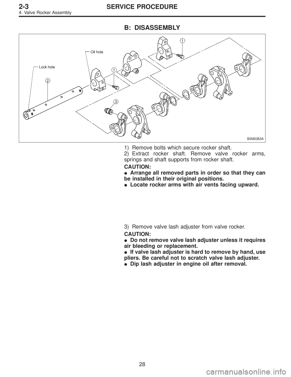
B: DISASSEMBLY
B2M0383A
1) Remove bolts which secure rocker shaft.
2) Extract rocker shaft. Remove valve rocker arms,
springs and shaft supports from rocker shaft.
CAUTION:
�Arrange all removed parts in order so that they can
be installed in their original positions.
�Locate rocker arms with air vents facing upward.
3) Remove valve lash adjuster from valve rocker.
CAUTION:
�Do not remove valve lash adjuster unless it requires
air bleeding or replacement.
�If valve lash adjuster is hard to remove by hand, use
pliers. Be careful not to scratch valve lash adjuster.
�Dip lash adjuster in engine oil after removal.
28
2-3SERVICE PROCEDURE
4. Valve Rocker Assembly
Page 340 of 2890
D: ASSEMBLY
B2M0383B
Tightening torque: N⋅m (kg-m, ft-lb)
T: 5±1 (0.5±0.1, 3.6±0.7)
1) After bleeding air from hydraulic lash adjuster, position
hydraulic lash adjuster in valve rocker arm while dipping in
engine oil.
CAUTION:
�Fill rocker arm oil reservoir chamber with engine oil.
�Install a new hydraulic lash adjuster O-ring, being
careful not to scratch it.
�Do not attempt to rotate hydraulic lash adjuster dur-
ing installation.
2) Arrange valve rocker arms, springs and shaft supports
in assembly order and insert valve rocker shaft. Ensure
that cutout portion of rocker shaft faces oil holes�
Ain shaft
supports.
CAUTION:
Valve rocker arms, rocker shaft and shaft supports
have identification marks. Ensure parts with same
markings are properly assembled.
3) Install valve rocker shaft securing bolts while aligning
shaft“lock”holes�
Bwith bolts.
31
2-3SERVICE PROCEDURE
4. Valve Rocker Assembly
Page 362 of 2890
G2M0163
7) Removal of oil pan
(1) Turn cylinder block with #2 and #4 piston sides
facing upward.
(2) Remove bolts which secure oil pan to cylinder
block.
(3) Insert a oil pan cutter blade between cylinder block-
to-oil pan clearance and remove oil pan.
CAUTION:
Do not use a screwdriver or similar tool in place of oil-
pan cutter.
8) Remove oil strainer stay.
9) Remove oil strainer.
10) Remove baffle plate.
11) Remove oil filter.
B: DISASSEMBLY
1. PISTON PIN AND CYLINDER BLOCK
CONNECTING BOLT
G2M0164
52
2-3SERVICE PROCEDURE
7. Cylinder Block
Page 439 of 2890
B2M0706A
2) Remove drive plate.
To lock crankshaft use ST.
ST 498497100 CRANKSHAFT STOPPER
3) Remove oil separator cover.
4) Remove engine coolant pipe.
5) Remove engine coolant pump.
G2M0162
6) Remove oil pump from cylinder block.
Use a flat-bladed screwdriver as shown in Figure when
removing oil pump.
CAUTION:
Be careful not to scratch the mating surface of cylin-
der block and oil pump.
G2M0163
7) Removal of oil pan
(1) Turn cylinder block with #2 and #4 piston sides
facing upward.
(2) Remove bolts which secure oil pan to cylinder
block.
(3) Insert a oil pan cutter blade between cylinder block-
to-oil pan clearance and remove oil pan.
CAUTION:
Do not use a screwdriver or similar tool in place of oil-
pan cutter.
8) Remove oil strainer stay.
9) Remove oil strainer.
10) Remove baffle plate.
11) Remove oil filter.
51
2-3bSERVICE PROCEDURE
5. Cylinder Block
![SUBARU LEGACY 1996 Service Repair Manual
ON-BOARD
DIAGNOSTICS
II
SYSTEM
[TloBVi]
2-7
10
.
Diagnostics
Chart
with
Trouble
Code
Test
mode
connector
B2M04328
10BV1
I
CHECK
FUEL
TANK
PRESSURE
CONTROL
SOLENOID
VALVE
.
1)
Turn
ignition
swit](/manual-img/17/57433/w960_57433-254.png "SUBARU LEGACY 1996 Service Repair Manual
ON-BOARD
DIAGNOSTICS
II
SYSTEM
[TloBVi]
2-7
10
.
Diagnostics
Chart
with
Trouble
Code
Test
mode
connector
B2M04328
10BV1
I
CHECK
FUEL
TANK
PRESSURE
CONTROL
SOLENOID
VALVE
.
1)
Turn
ignition
swit")
![SUBARU LEGACY 1996 Service Repair Manual 2-7
RyoBxo]
ON-BOARD
DIAGNOSTICS
II
SYSTEM
10
.
DiagnosticsChart
with
Trouble
Code
OBD
(
F
B
1)
EXERR22
B2M0947
BX
:
DTC
P0461
-
FUEL
LEVEL
SENSOR
CIRCUIT
RANGE/
PERFORMANCEPROBLEM
(EXERR22)
-](/manual-img/17/57433/w960_57433-264.png "SUBARU LEGACY 1996 Service Repair Manual 2-7
RyoBxo]
ON-BOARD
DIAGNOSTICS
II
SYSTEM
10
.
DiagnosticsChart
with
Trouble
Code
OBD
(
F
B
1)
EXERR22
B2M0947
BX
:
DTC
P0461
-
FUEL
LEVEL
SENSOR
CIRCUIT
RANGE/
PERFORMANCEPROBLEM
(EXERR22)
-")

T: 5±1 (0.5±0.1, 3.6±0.7)
1) After bleeding air from hydraulic lash adjuster, position
hydraulic lash adjuster in valve rocker arm while")
 Removal of oil pan
(1) Turn cylinder block with #2 and #4 piston sides
facing upward.
(2) Remove bolts which secure oil pan to cylinder
block.
(3) Insert a oil pan cutter blade between cyli")
 Remove drive plate.
To lock crankshaft use ST.
ST 498497100 CRANKSHAFT STOPPER
3) Remove oil separator cover.
4) Remove engine coolant pipe.
5) Remove engine coolant pump.
G2M0162
6) Remov")