Page 996 of 2890
 Install rear cover and tighten bolts to specified torque.
Tightening torque:
29±5 N⋅m (3.0±0.5 kg-m, 21.7±3.6 ft-lb)
F: INSTALLATION
To install, reverse the removal sequence.
1) Insta")
G3M1050
19) Install rear cover and tighten bolts to specified torque.
Tightening torque:
29±5 N⋅m (3.0±0.5 kg-m, 21.7±3.6 ft-lb)
F: INSTALLATION
To install, reverse the removal sequence.
1) Install the air breather cap tapping with a plastic ham-
mer.
CAUTION:
Be sure to install new air breather cap.
2) Position front member on body by passing it under park-
ing brake cable and securing to rear differential.
NOTE:
When installing rear differential front member, do not con-
fuse the installation sequence of the upper and lower stop-
pers.
G3M1026
3) Install DOJ of rear drive shaft into rear differential.
to 3-4 [W2A2].>
ST 28099PA090 SIDE OIL SEAL PROTECTOR
G3M1051
4) Installing procedure hereafter is in the reverse order of
removal.
5) After installation, fill differential carrier with gear oil to
the upper plug level.
CAUTION:
Apply fluid packing to plug.
Fluid packing:
THREE BOND 1205 or equivalent
Oil capacity:
0.8�(0.8 US qt, 0.7 Imp qt)
Tightening torque:
44±4 N⋅m (4.5±0.4 kg-m, 32.5±2.9 ft-lb)
37
3-4SERVICE PROCEDURE
2. Rear Differential
Page 998 of 2890
G3M1029
B: INSTALLATION
To install, reverse the removal sequence.
1) Position front member on body by passing it under park-
ing brake cable and securing to rear differential.
G3M0101
NOTE:
When installing rear differential front member, do not con-
fuse the installation sequence of the stopper.
G3M1026
2) Insert DOJ of rear drive shaft into rear differential.
ST 28099PA090 SIDE OIL SEAL PROTECTOR
CAUTION:
Before inserting, replace the differential side oil seal
and the circlip at the end of the spline shaft with a new
one.
3) Installing procedure hereafter is in the reverse order of
removal.
39
3-4SERVICE PROCEDURE
3. Rear Differential Front Member
Page 1017 of 2890
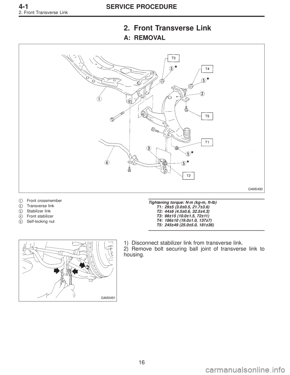
2. Front Transverse Link
A: REMOVAL
G4M0490
�1Front crossmember
�
2Transverse link
�
3Stabilizer link
�
4Front stabilizer
�
5Self-locking nut
Tightening torque: N⋅m (kg-m, ft-lb)
T1: 29±5 (3.0±0.5, 21.7±3.6)
T2: 44±6 (4.5±0.6, 32.5±4.3)
T3: 98±15 (10.0±1.5, 72±11)
T4: 186±10 (19.0±1.0, 137±7)
T5: 245±49 (25.0±5.0, 181±36)
G4M0491
1) Disconnect stabilizer link from transverse link.
2) Remove bolt securing ball joint of transverse link to
housing.
16
4-1SERVICE PROCEDURE
2. Front Transverse Link
Page 1018 of 2890
G4M0492
3) Remove nut (do not remove bolt.) securing transverse
link to crossmember.
4) Remove two bolts securing bushing bracket of trans-
verse link to vehicle body at rear bushing location.
G4M0493
5) Extract ball joint from housing.
6) Remove bolt securing transverse link to crossmember
and extract transverse link from crossmember.
G4M0494
B: DISASSEMBLY
1. FRONT BUSHING
Using ST, press front bushing out of place.
ST 927680000 INSTALLER & REMOVER SET
G4M0495
2. REAR BUSHING
1) Scribe an aligning mark on transverse link and rear
bushing.
2) Loosen nut and remove rear bushing.
C: INSPECTION
1) Check transverse link for wear, damage and cracks,
and correct or replace if defective.
2) Check bushings for cracks, wear,damage and creeping.
3) Check rear bushing for oil leaks.
4) If defective, replace with new one.
17
4-1SERVICE PROCEDURE
2. Front Transverse Link
Page 1019 of 2890
 Install rear bushing to")
G4M0496
D: ASSEMBLY
1. FRONT BUSHING
To reassemble, reverse disassembly procedures.
CAUTION:
Install front bushing in correct direction, as shown in
figure.
2. REAR BUSHING
1) Install rear bushing to transverse link and align aligning
marks scribed on the two.
2) Tighten self-locking nut.
CAUTION:
�Discard loosened self-locking nut and replace with a
new one.
�While holding rear bushing so as not to change
position of aligning marks, tighten self-locking nut.
Tightening torque:
186±10 N⋅m (19.0±1.0 kg-m, 137±7 ft-lb)
E: INSTALLATION
1) Temporarily tighten the two bolts used to secure rear
bushing of the transverse link to body.
NOTE:
These bolts should be tightened to such an extent that they
can still move back and forth in the oblong shaped hole in
the bracket (which holds the bushing).
2) Install bolts used to connect transverse link to cross-
member and temporarily tighten with nut.
CAUTION:
Discard loosened self-locking nut and replace with a
new one.
3) Insert ball joint into housing.
18
4-1SERVICE PROCEDURE
2. Front Transverse Link
Page 1021 of 2890
 Remove the wheel.
2) Pull out the cotter pin from the ball stud, remove the
castle nut, and extract the ball stud from the transverse
link.
3) Remove the bolt")
G4M0499
3. Front Ball Joint
A: REMOVAL
1) Remove the wheel.
2) Pull out the cotter pin from the ball stud, remove the
castle nut, and extract the ball stud from the transverse
link.
3) Remove the bolt securing the ball joint to the housing.
4) Extract the ball joint from the housing.
G4M0500
B: INSPECTION
1) Measure play of ball joint by the following procedures.
Replace with a new one when the play exceeds the speci-
fied value.
(1) With 686 N (70 kg, 154 lb) loaded in the direction
shown in the figure, measure dimension�
1.
G4M0501
(2) With 686 N (70 kg, 154 lb) loaded in the opposite
direction shown in the figure, measure dimension�
2.
(3) Calculate plays from the following formula.
S=�
2��1(4) When plays are larger than the following value,
replace with a new one.
FRONT BALL JOINT
Specified play for replacement: S
Less than 0.3 mm (0.012 in)
2) When play is smaller than the specified value, visually
inspect the dust cover.
3) If the dust cover is damaged, replace with the new ball
joint.
4) Check ball joint for damage and cracks. If defective,
replace with new one.
C: INSTALLATION
1) Install ball joint onto housing.
Torque (Bolt):
49±10 N⋅m (5.0±1.0 kg-m, 36±7 ft-lb)
CAUTION:
Do not apply grease to tapered portion of ball stud.
2) Connect ball joint to transverse link.
Torque (Castle nut):
39 N⋅m (4.0 kg-m, 29 ft-lb)
3) Retighten castle nut further within 60°until a slot in
castle nut is aligned with the hole of ball stud end, then
insert new cotter pin and bend it around castle nut.
4) Install front wheel.
20
4-1SERVICE PROCEDURE
3. Front Ball Joint
Page 1023 of 2890
G4M0504
4) Remove brake hose clamp and disconnect brake hose
from strut. Attach brake hose to body using gum tape.
5) Scribe an alignment mark on the camber adjusting bolt
which secures strut to housing.
6) Remove bolt securing the A.B.S. sensor harness.
(A.B.S. equipped models.)
G4M0505
7) Remove two bolts securing housing to strut.
CAUTION:
While holding head of adjusting bolt, loosen self-lock-
ing nut.
8) Remove the three nuts securing strut mount to body.
G4M0506
B: DISASSEMBLY
1) Using a coil spring compressor, compress coil spring.
G4M0507
2) Using ST, remove self-locking nut.
ST 927760000 STRUT MOUNT SOCKET
3) Remove strut mount, upper spring seat and rubber seat
from strut.
4) Gradually decreasing compression force of spring
compressor, and remove coil spring.
5) Remove dust cover and helper.
22
4-1SERVICE PROCEDURE
4. Front Strut
Page 1026 of 2890
 Pull the piston rod fully upward, and install rubber seat
and spring seat.
NOTE:
Ensure that upper spring seat is positioned with“OUT”
mark facing outward.
8) Install strut mount to the")
G4M0511
7) Pull the piston rod fully upward, and install rubber seat
and spring seat.
NOTE:
Ensure that upper spring seat is positioned with“OUT”
mark facing outward.
8) Install strut mount to the piston rod, and tighten the
self-locking nut temporarily.
CAUTION:
Be sure to use a new self-locking nut.
G4M0507
9) Using hexagon wrench to prevent strut rod from turning,
tighten self-locking nut with ST.
Tightening torque:
54±5 N⋅m (5.5±0.5 kg-m, 39.8±3.6 ft-lb)
ST 927760000 STRUT MOUNT SOCKET
10) Loosen the coil spring carefully.
E: INSTALLATION
1) Install strut mount at upper side of strut to body and
tighten with nuts.
Tightening torque:
20±6 N⋅m (2.0±0.6 kg-m, 14.5±4.3 ft-lb)
2) Connect housing to lower side of strut.
3) Position aligning mark on camber adjusting bolt with
aligning mark on lower side bracket of strut.
CAUTION:
�While holding head of adjusting bolt, tighten self-
locking nut.
�Be sure to use new self-locking nut.
Tightening torque:
152±20 N⋅m (15.5±2.0 kg-m, 112±14 ft-lb)
4) Install A.B.S. sensor harness to strut. (A.B.S. equipped
models.)
Tightening torque:
152±20 N⋅m (15.5±2.0 kg-m, 112±14 ft-lb)
5) Install brake hose at lower side of strut with clamp.
G4M0503
6) Install union bolts which secure brake caliper to brake
hose.
Tightening torque:
18±3 N⋅m (1.8±0.3 kg-m, 13.0±2.2 ft-lb)
CAUTION:
Be sure to bleed air from brake system.
7) Install wheels.
NOTE:
Check wheel alignment and adjust if necessary.
25
4-1SERVICE PROCEDURE
4. Front Strut
 Position front member on body by passing it under park-
ing brake cable and securing to rear differential.
G3M0101
NOTE:
When insta")
 Remove nut (do not remove bolt.) securing transverse
link to crossmember.
4) Remove two bolts securing bushing bracket of trans-
verse link to vehicle body at rear bushing location.
G4M0493")
 Remove brake hose clamp and disconnect brake hose
from strut. Attach brake hose to body using gum tape.
5) Scribe an alignment mark on the camber adjusting bolt
which secures strut to housi")