Page 2095 of 2890
OBD0676A
10BL5CHECK POWER SUPPLY TO PRESSURE
SOURCES SWITCHING SOLENOID
VA LV E .
1) Turn ignition switch to ON.
2) Measure voltage between pressure sources switching
solenoid valve harness connector and engine ground.
: Connector & terminal
(B1) No. 2 (+)—Engine ground (�):
Is the voltage more than 10 V?
: Go to next.
: Repair open circuit in harness between main relay
and pressure sources switching solenoid valve
connector.
: Is there poor contact in pressure sources
switching solenoid valve connector?
: Repair poor contact in pressure sources switching
solenoid valve connector.
: Contact with SOA service.
NOTE:
Inspection by DTM is required, because probable cause is
deterioration of multiple parts.
327
2-7ON-BOARD DIAGNOSTICS II SYSTEM
10. Diagnostics Chart with Trouble Code
Page 2104 of 2890
B2M0932A
10BN5CHECK POWER SUPPLY TO FUEL TANK
PRESSURE CONTROL SOLENOID
VA LV E .
1) Turn ignition switch to ON.
2) Measure voltage between fuel tank pressure control
solenoid valve and chassis ground.
: Connector & terminal
(R68) No. 1 (+)—Chassis ground (�):
Is the voltage more than 10 V?
: Go to next.
: Repair harness and connector.
NOTE:
In this case, repair the following:
�Open circuit in harness between main relay and fuel tank
pressure control solenoid valve connector
�Poor contact in coupling connectors (B97 and R57)
�Poor contact in main relay connector
: Is there poor contact in fuel tank pressure
control solenoid valve connector?
: Repair poor contact in fuel tank pressure control
solenoid valve connector.
: Contact with SOA service.
NOTE:
Inspection by DTM is required, because probable cause is
deterioration of multiple parts.
336
2-7ON-BOARD DIAGNOSTICS II SYSTEM
10. Diagnostics Chart with Trouble Code
Page 2119 of 2890
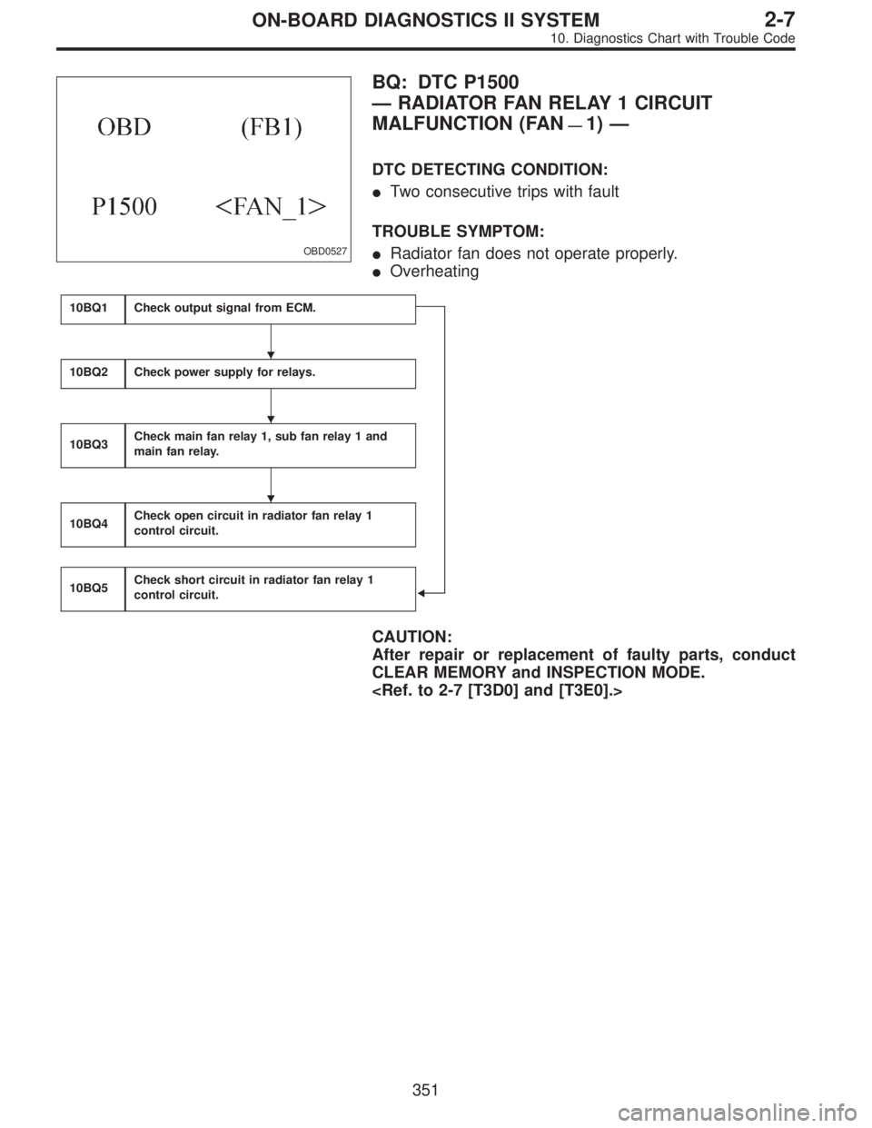
OBD0527
BQ: DTC P1500
—RADIATOR FAN RELAY 1 CIRCUIT
MALFUNCTION (FAN
—1)—
DTC DETECTING CONDITION:
�Two consecutive trips with fault
TROUBLE SYMPTOM:
�Radiator fan does not operate properly.
�Overheating
10BQ1Check output signal from ECM.
�
10BQ2Check power supply for relays.
10BQ3Check main fan relay 1, sub fan relay 1 and
main fan relay.
10BQ4Check open circuit in radiator fan relay 1
control circuit.
10BQ5Check short circuit in radiator fan relay 1
control circuit.
CAUTION:
After repair or replacement of faulty parts, conduct
CLEAR MEMORY and INSPECTION MODE.
�
�
�
351
2-7ON-BOARD DIAGNOSTICS II SYSTEM
10. Diagnostics Chart with Trouble Code
Page 2122 of 2890
10BQ2
CHECK POWER SUPPLY FOR RELAYS.
Turn ignition switch to OFF.
: Is the fuse in power supply circuit broken?
: Replace the fuse.
: Go to step10BQ3.
OBD0535
10BQ3CHECK MAIN FAN RELAY 1, SUB FAN
RELAY 1 AND MAIN FAN RELAY.
1) Remove main fan relay 1. (With A/C models only)
2) Measure resistance between main fan relay 1 termi-
nals.
: Terminal
No. 1—No. 3:
Is the resistance between 87 and 107Ω?
: Go to next step 3).
: Replace main fan relay 1.
OBD0536
3) Remove sub fan relay 1. (With A/C models only)
Remove main fan relay. (Without A/C models only)
4) Measure resistance between sub fan relay 1 or main
fan relay terminals.
: Terminal
No. 1—No. 3:
Is the resistance between 83 and 117Ω?
: Go to step10BQ4.
: Replace sub fan relay 1.
354
2-7ON-BOARD DIAGNOSTICS II SYSTEM
10. Diagnostics Chart with Trouble Code
Page 2123 of 2890
 Disconnect connector from ECM.
2) Disconnect connector from sub fan relay 1 or main fan
relay.
3) Measure resistance of har")
B2M0609A
10BQ4CHECK OPEN CIRCUIT IN RADIATOR
FAN RELAY 1 CONTROL CIRCUIT.
1) Disconnect connector from ECM.
2) Disconnect connector from sub fan relay 1 or main fan
relay.
3) Measure resistance of harness between ECM and main
fan relay 1 connector.
NOTE:
With A/C models only.
: Connector & terminal
(B84) No. 74—(F28) No. 3:
Is the resistance less than 1Ω?
: Go to next.
: Repair open circuit in harness between ECM and
main fan relay 1 connector.
: Is there poor contact in ECM or main fan
relay 1 connector?
: Repair poor contact in ECM or main fan relay 1
connector.
: Go to next step 4).
B2M0610A
4) Measure resistance of harness between ECM and sub
fan relay 1 (with A/C models) or main fan relay (without A/C
models) connector.
: Connector & terminal
(B84) No. 74—(F40) No. 4:
Is the resistance less than 1Ω?
: Go to next.
: Repair open circuit in harness between ECM and
sub fan relay 1 (with A/C models) or main fan relay
(without A/C models) connector.
: Is there poor contact in ECM or sub fan
relay 1 (with A/C models) or main fan relay
(without A/C models) connector?
: Repair poor contact in ECM or sub fan relay 1 (with
A/C models) or main fan relay (without A/C mod-
els) connector.
: Go to next step 5) (with A/C models) or step 6)
(without A/C models).
355
2-7ON-BOARD DIAGNOSTICS II SYSTEM
10. Diagnostics Chart with Trouble Code
Page 2124 of 2890
 Measure resistance of harness between main fan relay
1 and ignition switch connector.
NOTE:
With A/C models only.
: Connector & terminal
(F28) No. 1—(F72) No. 5:
Is the resistance less t")
OBD0686A
5) Measure resistance of harness between main fan relay
1 and ignition switch connector.
NOTE:
With A/C models only.
: Connector & terminal
(F28) No. 1—(F72) No. 5:
Is the resistance less than 1Ω?
: Go to next.
: Repair open circuit in harness between main fan
relay 1 and ignition switch connector.
: Is there poor contact in main fan relay 1 or
ignition switch connector?
: Repair main fan relay 1 or ignition switch connec-
tor.
: Go to next step 6).
OBD0687A
6) Measure resistance of harness between sub fan relay
1 (with A/C models) or main fan relay (without A/C models)
and ignition switch connector.
: Connector & terminal
(B52) No. 4—(F72) No. 2:
Is the resistance less than 1Ω?
: Go to next.
: Repair open circuit in harness between sub fan
relay 1 (with A/C models) or main fan relay (with-
out A/C models) and ignition switch connector.
: Is there poor contact in sub fan relay 1 (with
A/C models) or main fan relay (without A/C
models) or ignition switch connector?
: Repair poor contact in sub fan relay 1 (with A/C
models) or main fan relay (without A/C models) or
ignition switch connector.
: Replace ECM.
356
2-7ON-BOARD DIAGNOSTICS II SYSTEM
10. Diagnostics Chart with Trouble Code
Page 2125 of 2890
B2M0611A
10BQ5CHECK SHORT CIRCUIT IN RADIATOR
FAN RELAY 1 CONTROL CIRCUIT.
1) Turn ignition switch to OFF.
2) Remove main fan relay 1 and sub fan relay 1. (with A/C
models)
Remove main fan relay. (without A/C models)
3) Disconnect test mode connector.
4) Turn ignition switch to ON.
5) Measure voltage between ECM and chassis ground.
: Connector & terminal
(B84) No. 74 (+)—Chassis ground (�):
Is the voltage more than 10 V?
: Repair short circuit in radiator fan relay 1 control
circuit and replace ECM.
: Go to next.
: Is there poor contact in ECM connector?
: Repair poor contact in ECM connector.
: Replace ECM.
357
2-7ON-BOARD DIAGNOSTICS II SYSTEM
10. Diagnostics Chart with Trouble Code
Page 2217 of 2890
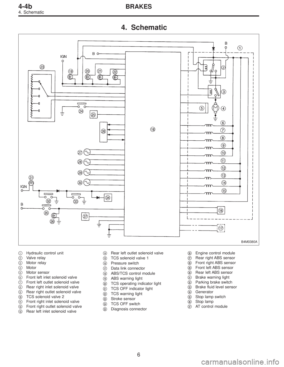
4. Schematic
B4M0380A
�1Hydraulic control unit
�
2Valve relay
�
3Motor relay
�
4Motor
�
5Motor sensor
�
6Front left inlet solenoid valve
�
7Front left outlet solenoid valve
�
8Rear right inlet solenoid valve
�
9Rear right outlet solenoid valve
�
10TCS solenoid valve 2
�
11Front right inlet solenoid valve
�
12Front right outlet solenoid valve
�
13Rear left inlet solenoid valve�
14Rear left outlet solenoid valve
�
15TCS solenoid valve 1
�
16Pressure switch
�
17Data link connector
�
18ABS/TCS control module
�
19ABS warning light
�
20TCS operating indicator light
�
21TCS OFF indicator light
�
22TCS warning light
�
23Stroke sensor
�
24TCS OFF switch
�
25Diagnosis connector�
26Engine control module
�
27Rear right ABS sensor
�
28Front right ABS sensor
�
29Front left ABS sensor
�
30Rear left ABS sensor
�
31Brake warning light
�
32Parking brake switch
�
33Brake fluid level sensor
�
34Generator
�
35Stop lamp switch
�
36Stop lamp
�
37AT control module
6
4-4bBRAKES
4. Schematic
 Turn ignition switch to ON.
2) Measure voltage between pressure sources switching
solenoid valve harness connector")
 Turn ignition switch to ON.
2) Measure voltage between fuel tank pressure control
solenoid valve and chassis ground")

 Turn ignition switch to OFF.
2) Remove main fan relay 1 and sub fan relay 1. (with A/C
models)
Remove main fan relay. (wit")