Page 2305 of 2890
CodeDisplay screen
(FB0)Diagnostic items (select monitor FB1) Display screen (FB1)Ref. to
4-4b
Normal 11 NO TROUBLE Normal NO TROUBLE [T10C")
B: LIST OF TROUBLE CODE
Diagnostic items
(select monitor FB0)CodeDisplay screen
(FB0)Diagnostic items (select monitor FB1) Display screen (FB1)Ref. to
4-4b
Normal 11 NO TROUBLE Normal NO TROUBLE [T10C0]
Detection of FR sensor
hardware21 FR.SS HARDOpen circuit of FR sensor FR.SS OPEN [T10D1]
Short circuit of FR sensor FR.SS SHORT [T10D2]
Detection of FR sensor
software22 FR.SS SOFTFR sensor, variations in wheel speed FR.SS W.SPEED [T10E1]
FR sensor, reduced pressure mode FR.SS OR MV [T10E2]
FR sensor, wheel speed higher than prescribed FR.SS OVER [T10E3]
Detection of FL sensor
hardware23 FL.SS HARDOpen circuit of FL sensor FL.SS OPEN [T10F1]
Short circuit of FL sensor FL.SS SHORT [T10F2]
Detection of FL sensor
software24 FL.SS SOFTFL sensor, variations in wheel speed FL.SS W.SPEED [T10G1]
FL sensor, reduced pressure mode FL.SS OR MV [T10G2]
FL sensor, wheel speed higher than prescribed FL.SS OVER [T10G3]
Detection of RR sensor
hardware25 RR.SS HARDOpen circuit of RR sensor RR.SS OPEN [T10H1]
Short circuit of RR sensor RR.SS SHORT [T10H2]
Detection of RR sensor
software26 RR.SS SOFTRR sensor, variations in wheel speed RR.SS W.SPEED [T10I1]
RR sensor, reduced pressure mode RR.SS OR MV [T10I2]
RR sensor, wheel speed higher than prescribed RR.SS OVER [T10I3]
Detection of RL sensor
hardware27 RL.SS HARDOpen circuit of RL sensor RL.SS OPEN [T10J1]
Short circuit of RL sensor RL.SS SHORT [T10J2]
Detection of RL sensor
software28 RL.SS SOFTRL sensor, variations in wheel speed RL.SS W.SPEED [T10K1]
RL sensor, reduced pressure mode RL.SS OR MV [T10K2]
RL sensor, wheel speed higher than prescribed RL.SS OVER [T10K3]
Abnormal FR.IN valve 31 FR.IN VALVE Abnormal FR.IN valve FR.IN VALVE [T10L0]
Abnormal FR.OUT
valve32 FR.OUT VALVE Abnormal FR.OUT valve FR.OUT VALVE [T10M0]
Abnormal FL.IN valve 33 FL.IN VALVE Abnormal FL.IN valve FL.IN VALVE [T10N0]
Abnormal FL.OUT
valve34 FL.OUT VALVE Abnormal FL.OUT valve FL.OUT VALVE [T10O0]
Abnormal RR.IN valve 35 RR.IN VALVE Abnormal RR.IN valve RR.IN VALVE [T10P0]
Abnormal RR.OUT
valve36 RR.OUT VALVE Abnormal RR.OUT valve RR.OUT VALVE [T10Q0]
Abnormal RL.IN valve 37 RL.IN VALVE Abnormal RL.IN valve RL.IN VALVE [T10R0]
Abnormal RL.OUT
valve38 RL.OUT VALVE Abnormal RL.OUT valve RL.OUT VALVE [T10S0]
Abnormal ECM 41 ECU Abnormal ECM ECU [T10T0]
Abnormal line voltage 42 HIGH VOLTAGE Abnormal line voltage HIGH VOLTAGE [T10U0]
Abnormal EGI commu-
nication line43 EGI LINE Abnormal EGI communication line EGI LINE [T10V0]
Abnormal valve relay 51 V.RELAYValve relay ON failure V.RELAY ON [T10W1]
Valve relay OFF failure V.RELAY OFF [T10W2]
Abnormal motor sys-
tem52 MOTORMotor relay ON failure MOTOR ON [T10X1]
Motor relay OFF failure MOTOR OFF [T10X2]
94
4-4bBRAKES
10. Diagnostic Chart with Select Monitor
Page 2306 of 2890
CodeDisplay screen
(FB0)Diagnostic items (select monitor FB1) Display screen (FB1)Ref. to
4-4b
Abnormal stroke sen-
sor and stop light
switch54 PSS & BLSOpen/short")
Diagnostic items
(select monitor FB0)CodeDisplay screen
(FB0)Diagnostic items (select monitor FB1) Display screen (FB1)Ref. to
4-4b
Abnormal stroke sen-
sor and stop light
switch54 PSS & BLSOpen/short circuits of stroke sensor B.SW HARD [T10Y1]
Comparison of stroke sensor and acceleration B.SW SOFT(G) [T10Y2]
Comparison of stroke sensor and stop light switch B.SW SOFT(B) [T10Y3]
Comparison of stroke sensor and pump B.SW SOFT(P) [T10Y4]
Open circuit of stop light switch B.SW SOFT(O) [T10Y5]
Abnormal fluid level
sensor line57 FLUID LEVEL SS Abnormal fluid level sensor line FLUID LEVEL SS [T10Z0]
Abnormal pressure
switch58 PRESSURE SW Abnormal pressure switch PRESSURE SW [T10AA0]
Abnormal TCS1 valve 61 TCS1 VALVE Abnormal TCS1 valve TCS1 VALVE [T10AB0]
Abnormal TCS2 valve 62 TCS2 VALVE Abnormal TCS2 valve TCS2 VALVE [T10AC0]
1. IF THE SELECT MONITOR IS USED FOR
TROUBLESHOOTING, IT IS ADVISED TO FOLLOW
THE PROCEDURE BELOW
1) Activate function FB0 to read the most recent trouble
code and record it.
2) Activate function FB1 to read all trouble codes and
record them.
(If troubles occur in the wheel speed sensor, stop & brake
switch, valve relay or motor system, detailed data on
troubles are displayed by the FB1 function, allowing you to
easily locate points where need repair.)
3) Perform troubleshooting mainly in the FB1 mode.
95
4-4bBRAKES
10. Diagnostic Chart with Select Monitor
Page 2325 of 2890
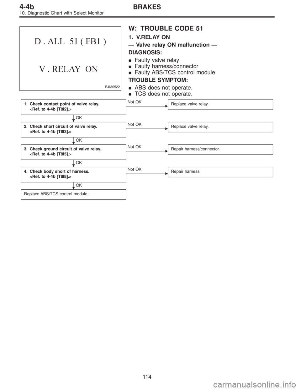
B4M0522
W: TROUBLE CODE 51
1. V.RELAY ON
—Valve relay ON malfunction—
DIAGNOSIS:
�Faulty valve relay
�Faulty harness/connector
�Faulty ABS/TCS control module
TROUBLE SYMPTOM:
�ABS does not operate.
�TCS does not operate.
1. Check contact point of valve relay.
OK
�Not OK
Replace valve relay.
2. Check short circuit of valve relay.
OK
�Not OK
Replace valve relay.
3. Check ground circuit of valve relay.
OK
�Not OK
Repair harness/connector.
4. Check body short of harness.
OK
�Not OK
Repair harness.
Replace ABS/TCS control module.
�
�
�
�
11 4
4-4bBRAKES
10. Diagnostic Chart with Select Monitor
Page 2326 of 2890
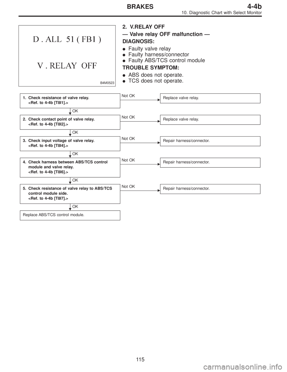
B4M0523
2. V.RELAY OFF
—Valve relay OFF malfunction—
DIAGNOSIS:
�Faulty valve relay
�Faulty harness/connector
�Faulty ABS/TCS control module
TROUBLE SYMPTOM:
�ABS does not operate.
�TCS does not operate.
1. Check resistance of valve relay.
OK
�Not OK
Replace valve relay.
2. Check contact point of valve relay.
OK
�Not OK
Replace valve relay.
3. Check input voltage of valve relay.
OK
�Not OK
Repair harness/connector.
4. Check harness between ABS/TCS control
module and valve relay.
OK
�Not OK
Repair harness/connector.
5. Check resistance of valve relay to ABS/TCS
control module side.
OK
�Not OK
Repair harness/connector.
Replace ABS/TCS control module.
�
�
�
�
�
11 5
4-4bBRAKES
10. Diagnostic Chart with Select Monitor
Page 2327 of 2890
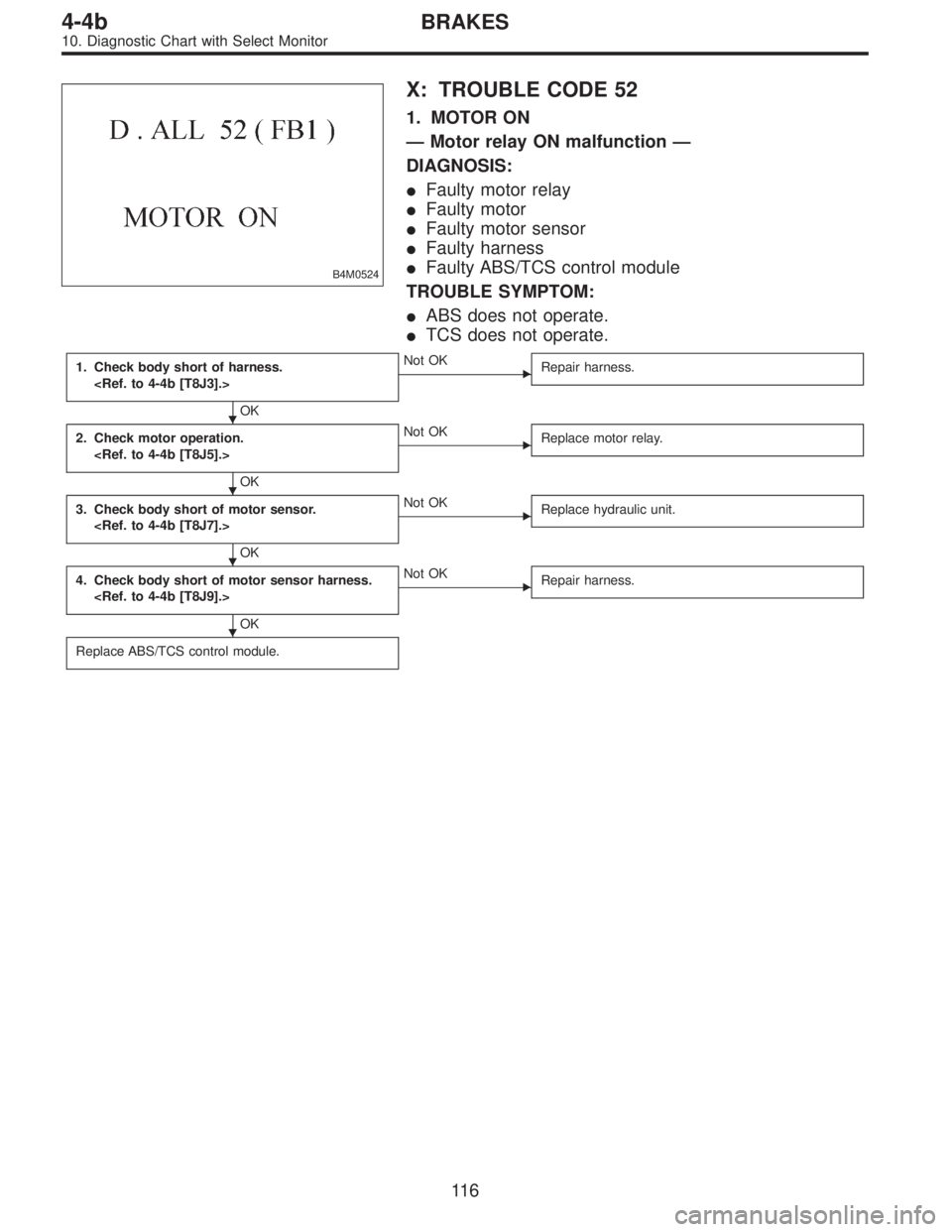
B4M0524
X: TROUBLE CODE 52
1. MOTOR ON
—Motor relay ON malfunction—
DIAGNOSIS:
�Faulty motor relay
�Faulty motor
�Faulty motor sensor
�Faulty harness
�Faulty ABS/TCS control module
TROUBLE SYMPTOM:
�ABS does not operate.
�TCS does not operate.
1. Check body short of harness.
OK
�Not OK
Repair harness.
2. Check motor operation.
OK
�Not OK
Replace motor relay.
3. Check body short of motor sensor.
OK
�Not OK
Replace hydraulic unit.
4. Check body short of motor sensor harness.
OK
�Not OK
Repair harness.
Replace ABS/TCS control module.
�
�
�
�
11 6
4-4bBRAKES
10. Diagnostic Chart with Select Monitor
Page 2328 of 2890
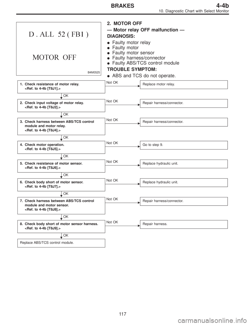
B4M0525
2. MOTOR OFF
—Motor relay OFF malfunction—
DIAGNOSIS:
�Faulty motor relay
�Faulty motor
�Faulty motor sensor
�Faulty harness/connector
�Faulty ABS/TCS control module
TROUBLE SYMPTOM:
�ABS and TCS do not operate.
1. Check resistance of motor relay.
OK
�Not OK
Replace motor relay.
2. Check input voltage of motor relay.
OK
�Not OK
Repair harness/connector.
3. Check harness between ABS/TCS control
module and motor relay.
OK
�Not OK
Repair harness/connector.
4. Check motor operation.
OK
�Not OK
Go to step 9.
5. Check resistance of motor sensor.
OK
�Not OK
Replace hydraulic unit.
6. Check body short of motor sensor.
OK
�Not OK
Replace hydraulic unit.
7. Check harness between ABS/TCS control
module and motor sensor.
OK
�Not OK
Repair harness/connector.
8. Check body short of motor sensor harness.
OK
�Not OK
Repair harness.
Replace ABS/TCS control module.
�
�
�
�
�
�
�
�
11 7
4-4bBRAKES
10. Diagnostic Chart with Select Monitor
Page 2329 of 2890
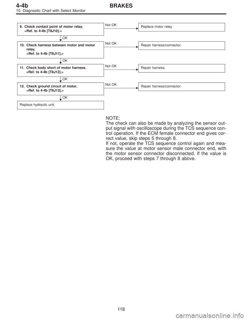
9. Check contact point of motor relay.
OK
�Not OK
Replace motor relay.
10. Check harness between motor and motor
relay.
OK
�Not OK
Repair harness/connector.
11. Check body short of motor harness.
OK
�Not OK
Repair harness.
12. Check ground circuit of motor.
OK
�Not OK
Repair harness/connector.
Replace hydraulic unit.
NOTE:
The check can also be made by analyzing the sensor out-
put signal with oscilloscope during the TCS sequence con-
trol operation. If the ECM female connector end gives cor-
rect value, skip steps 5 through 8.
If not, operate the TCS sequence control again and mea-
sure the value at motor sensor male connector end, with
the motor sensor connector disconnected. If the value is
OK, proceed with steps 7 through 8 above.
�
�
�
�
11 8
4-4bBRAKES
10. Diagnostic Chart with Select Monitor
Page 2344 of 2890
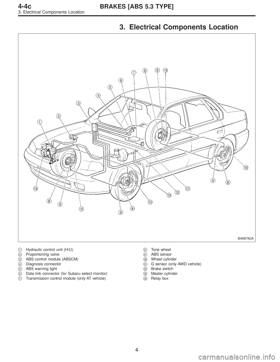
3. Electrical Components Location
B4M0782A
�1Hydraulic control unit (H/U)
�
2Proportioning valve
�
3ABS control module (ABSCM)
�
4Diagnosis connector
�
5ABS warning light
�
6Data link connector (for Subaru select monitor)
�
7Transmission control module (only AT vehicle)�
8Tone wheel
�
9ABS sensor
�
10Wheel cylinder
�
11G sensor (only AWD vehicle)
�
12Brake switch
�
13Master cylinder
�
14Relay box
4
4-4cBRAKES [ABS 5.3 TYPE]
3. Electrical Components Location