Page 2276 of 2890
 Turn ignition switch OFF.
2) Disconnect valve relay.
3) Disconnect ABS/TCS control module.
4) Measure resistance between AB")
B4M0446A
6. CHECK HARNESS BETWEEN ABS/TCS CONTROL
MODULE AND VALVE RELAY.
1) Turn ignition switch OFF.
2) Disconnect valve relay.
3) Disconnect ABS/TCS control module.
4) Measure resistance between ABS/TCS control module
connector and body.
Connector & terminal / Specified resistance:
(P6) No. 6—body/1MΩor more
5) Connect valve relay.
6) Measure resistance between ABS/TCS control module
connector and body.
Connector & terminal / Specified resistance:
(P6) No. 6—body / 1Ωor less
B4M0447A
7. CHECK RESISTANCE OF VALVE RELAY TO ABS/
TCS CONTROL MODULE SIDE.
1) Turn ignition switch OFF.
2) Connect valve relay.
3) Disconnect ABS/TCS control module.
4) Measure resistance between ABS/TCS control module
connector terminals.
Connector & terminal / Specified resistance:
(P5) No. 1—(P6) No. 1 / 90±10Ω
B4M0729A
8. CHECK BODY SHORT OF HARNESS.
1) Turn ignition switch OFF.
2) Connect valve relay.
3) Disconnect ABS/TCS control module.
4) Turn ignition switch ON.
5) Measure voltage between ABS/TCS control module
connector and body.
Connector & terminal / Specified voltage:
(P6) No. 1—body / 10—13 V
65
4-4bBRAKES
8. Diagnostics Chart with Trouble Code
Page 2277 of 2890

J: TROUBLE CODE 52
—FAULTY MOTOR, MOTOR SENSOR AND/
OR MOTOR RELAY—
DIAGNOSIS:
�Faulty motor relay
�Faulty motor
�Faulty motor sensor
�Faulty harness/connector
�Faulty ABS/TCS control module
TROUBLE SYMPTOM:
�ABS does not operate.
�TCS does not operate.
1. Check resistance of motor relay.
OK
�Not OK
Replace motor relay.
2. Check input voltage of motor relay.
OK
�Not OK
Repair harness/connector.
3. Check body short of harness.
OK
�Not OK
Repair harness.
4. Check harness between ABS/TCS control
module and motor relay.
OK
�Not OK
Repair harness/connector.
5. Check motor operation.
OK
�Not OK
Go to step 10.
6. Check resistance of motor sensor.
OK
�Not OK
Replace hydraulic unit.
7. Check body short of motor sensor.
OK
�Not OK
Replace hydraulic unit.
8. Check harness between ABS/TCS control
module and motor sensor.
OK
�Not OK
Repair harness/connector.
9. Check body short of motor sensor harness.
OK
�Not OK
Repair harness.
Replace ABS/TCS control module.
�
�
�
�
�
�
�
�
�
66
4-4bBRAKES
8. Diagnostics Chart with Trouble Code
Page 2278 of 2890
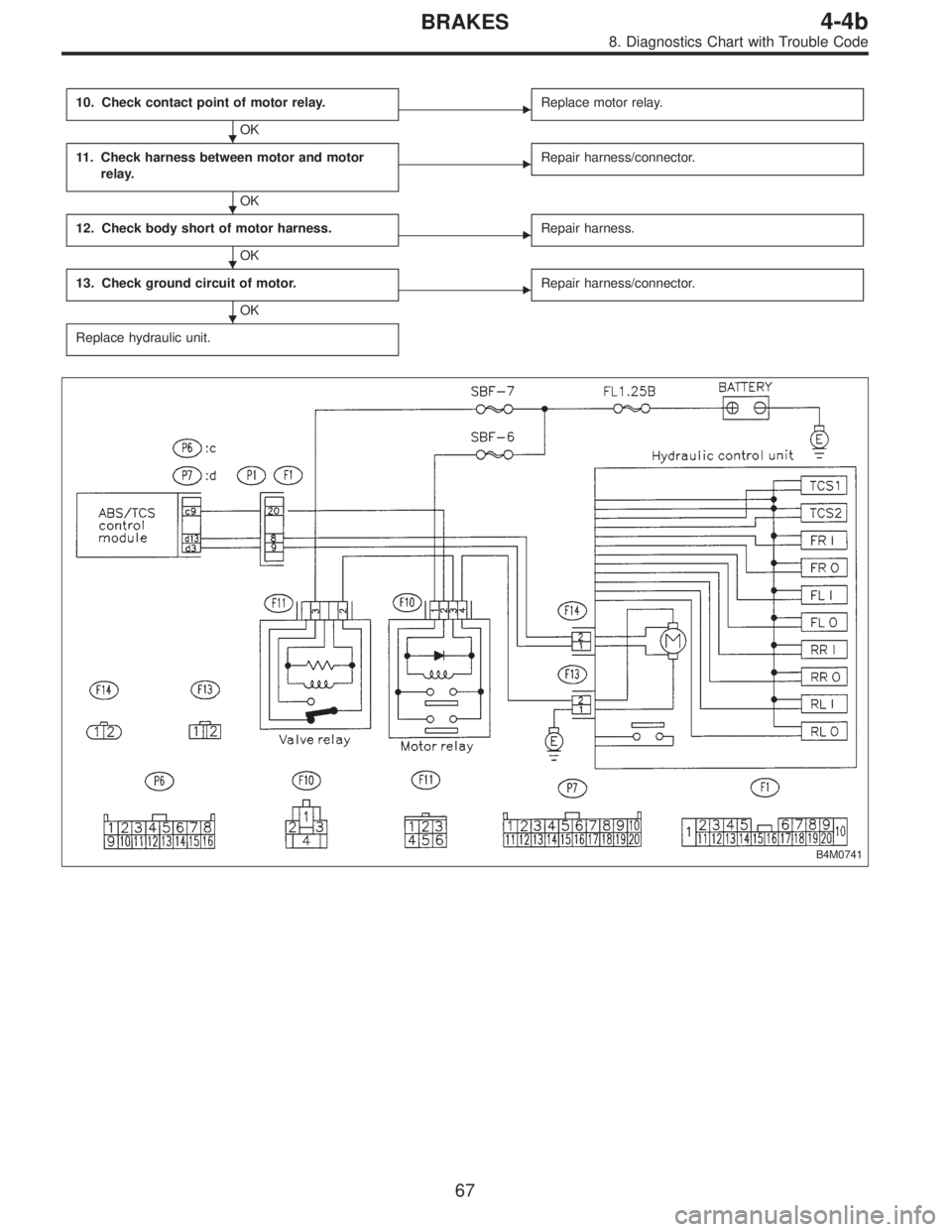
10. Check contact point of motor relay.
OK
�Replace motor relay.
11. Check harness between motor and motor
relay.
OK
�Repair harness/connector.
12. Check body short of motor harness.
OK
�Repair harness.
13. Check ground circuit of motor.
OK
�Repair harness/connector.
Replace hydraulic unit.
B4M0741
�
�
�
�
67
4-4bBRAKES
8. Diagnostics Chart with Trouble Code
Page 2279 of 2890
 Turn ignition switch OFF.
2) Remove motor relay.
3) Measure resistance between motor relay terminals.
Terminal / Specified resistance:
No. a—b/57Ω
N")
B4M0730A
1. CHECK RESISTANCE OF MOTOR RELAY.
1) Turn ignition switch OFF.
2) Remove motor relay.
3) Measure resistance between motor relay terminals.
Terminal / Specified resistance:
No. a—b/57Ω
NOTE:
Apply + to b terminal.
Apply � to a terminal.
B4M0451A
2. CHECK INPUT VOLTAGE OF MOTOR RELAY.
1) Turn ignition switch OFF.
2) Disconnect motor relay.
3) Measure voltage between motor relay connector and
body.
Connector & terminal / Specified voltage:
(F10) No. 1—body / 10—13 V
(F10) No. 3—body/0V
4) Turn ignition switch ON.
5) Measure voltage between motor relay connector and
body.
Connector & terminal / Specified voltage:
(F10) No. 1—body / 10—13 V
(F10) No. 3—body / 10—13 V (In 1 second after
turning ignition key ON.)
B4M0452A
3. CHECK BODY SHORT OF HARNESS.
1) Turn ignition switch OFF.
2) Disconnect motor relay.
3) Disconnect ABS/TCS control module.
4) Measure resistance between ABS/TCS control module
connector and body.
Connector & terminal / Specified resistance:
(P6) No. 9—body/1MΩor more
68
4-4bBRAKES
8. Diagnostics Chart with Trouble Code
Page 2280 of 2890
 Turn ignition switch OFF.
2) Connect motor relay.
3) Disconnect ABS/TCS control module.
4) Measure resistance between ABS/T")
B4M0731A
4. CHECK HARNESS BETWEEN ABS/TCS CONTROL
MODULE AND MOTOR RELAY.
1) Turn ignition switch OFF.
2) Connect motor relay.
3) Disconnect ABS/TCS control module.
4) Measure resistance between ABS/TCS control module
connector and body.
NOTE:
Apply + to GND.
Apply�to (P6) No. 9.
Connector & terminal / Specified resistance:
(P6) No. 9—body / 57±6Ω
5. CHECK MOTOR OPERATION.
1) Connect motor relay.
2) Connect ABS/TCS control module.
3) Operate the TCS sequence check.
4) By the whirring sound check that the motor rotates.
B4M0454A
6. CHECK RESISTANCE OF MOTOR SENSOR.
1) Turn ignition switch OFF.
2) Disconnect motor sensor connector.
3) Measure resistance between motor sensor connector
terminals.
Connector & terminal / Specified resistance:
(F14) No. 1—No.2/72—98Ω
B4M0455A
7. CHECK BODY SHORT OF MOTOR SENSOR.
1) Turn ignition switch OFF.
2) Disconnect motor sensor connector.
3) Measure resistance between motor sensor connector
and body.
Connector & terminal / Specified resistance:
(F14) No. 1—body/1MΩor more
(F14) No. 2—body/1MΩor more
69
4-4bBRAKES
8. Diagnostics Chart with Trouble Code
Page 2281 of 2890
 Turn ignition switch OFF.
2) Connect motor sensor connector.
3) Disconnect ABS/TCS control module.
4) Measure resistance b")
B4M0456A
8. CHECK HARNESS BETWEEN ABS/TCS CONTROL
MODULE AND MOTOR SENSOR.
1) Turn ignition switch OFF.
2) Connect motor sensor connector.
3) Disconnect ABS/TCS control module.
4) Measure resistance between ABS/TCS control module
connector terminals.
Connector & terminal / Specified resistance:
(P7) No. 3—No. 13 / 72—98Ω
B4M0457A
9. CHECK BODY SHORT OF MOTOR SENSOR
HARNESS.
1) Turn ignition switch OFF.
2) Connect motor sensor connector.
3) Disconnect ABS/TCS control module.
4) Measure resistance between ABS/TCS control module
and body.
Connector & terminal / Specified resistance:
(P7) No. 3—body/1MΩor more
(P7) No. 13—body/1MΩor more
B4M0458A
10. CHECK CONTACT POINT OF MOTOR RELAY.
1) Connect motor relay.
2) Connect ABS/TCS control module.
3) Operate the TCS sequence check.
[W20F0].>
4) Measure voltage between motor relay connector and
body.
Connector & terminal / Specified voltage:
(F10) No. 4—body / 10—14 V (While TCS oper-
ating indicator light is ON.)
B4M0459A
11. CHECK HARNESS BETWEEN MOTOR AND
MOTOR RELAY.
1) Turn ignition switch OFF.
2) Disconnect motor relay.
3) Disconnect motor connector.
4) Measure resistance between motor relay connector and
motor connector.
Connector & terminal / Specified resistance:
(F13) No. 2—(F10) No.4/1Ωor less
B4M0460A
12. CHECK BODY SHORT OF MOTOR HARNESS.
1) Turn ignition switch OFF.
2) Disconnect motor relay.
3) Disconnect motor connector.
4) Measure resistance between motor connector and
body.
Connector & terminal / Specified resistance:
(F13) No. 2—body/1MΩor more
70
4-4bBRAKES
8. Diagnostics Chart with Trouble Code
Page 2297 of 2890

If the system is in normal condition with the engine run at
idle speed (when the brake pedal is off), the LED of EC
(AEC signal) of FA2 will come on, the LED of")
2. FA MODE (ON/OFF DATA ARE DISPLAYED.)
If the system is in normal condition with the engine run at
idle speed (when the brake pedal is off), the LED of EC
(AEC signal) of FA2 will come on, the LED of EM (EAM
signal) blink and all other LED’s go out.
Function code
Measuring
itemsContents to be monitored Scroll Ref. to 4-4b
Code Abbreviation
FA 0OF OFF.SW LED 1 comes on with the OFF switch on.
Possible [T9H0] B1Stop light
switchLED 2 comes on with the switch on (with the brake
pedal down).
VRValve relay
signalLED 3 comes on with the valve relay off.
VMValve relay
monitorLED 4 comes on with the valve relay off.
MRMotor relay
signalLED 5 comes on with the motor on.
MS Motor sensor LED 6 comes on with the motor on.
FSFluid level
sensorLED 7 comes on with the sensor on (the fluid level
is lowered).
FA 1FI FR.IN valveLED 1 comes on when the FR.IN valve is operat-
ing.
Possible [T9I0] RO FR.OUT valveLED 2 comes on when the FR.OUT valve is operat-
ing.
FL FL.IN valve LED 3 comes on when the FL.IN valve is operating.
LO FL.OUT valveLED 4 comes on when the FL.OUT valve is operat-
ing.
T1 TCS1 valve LED 5 comes on when the TCS1 valve is operating.
RI RR.IN valveLED 6 comes on when the RR.IN valve is operat-
ing.
RO RR.OUT valveLED 7 comes on when the RR.OUT valve is operat-
ing.
RI RL.IN valve LED 8 comes on when the RL.IN valve is operating.
LO RL.OUT valveLED 9 comes on when the RL.OUT valve is operat-
ing.
T2 TCS2 valveLED 10 comes on when the TCS2 valve is operat-
ing.
FA 2AWABS warning
lightLED 1 comes on when the warning light is on.
Possible [T9J0] TWTCS warning
lightLED 2 comes on when the warning light is on.
TOTCS OFF
indicator lightLED 3 comes on when the indicator light is on.
TITCS operation
indicator lightLED 4 comes on when the indicator light is on.
EC AEC signalWith the engine run at idle speed, LED 6 (AEC)
comes on and LED 7 (AEB) goes out (They go on
and off depending on the behavior of a vehicle.) EB AEB signal
ET AET signal LED 8 comes on with the TCS control on.
EM EAM signalLED 9 comes on or blinks when the engine control
is enabled.
AT AAT signal LED 10 comes on when ABS control is on.
86
4-4bBRAKES
9. Select Monitor Function Mode
Page 2301 of 2890

—
�Compare speedometer with monitor indications.
�F04: RL wheel speed is indicated in mile per hour (mile/
h).
�F08: RL wheel speed i")
B4M0483
F: MODE F04 AND F08
—REAR LEFT WHEEL SPEED SIGNAL (RL)
—
�Compare speedometer with monitor indications.
�F04: RL wheel speed is indicated in mile per hour (mile/
h).
�F08: RL wheel speed is indicated in kilometer per hour
(km/h).
NOTE:
The monitor as shown, indicates that RL wheel speed is 50
mile/h.
B4M0484
G: MODE F09
—PEDAL STROKE SENSOR SIGNAL (PSS)
—
�Indicates the output step number of the pedal stroke
sensor.
LED No. Signal name Display
1 TCS OFF switch OF
2 Stop light switch B1
3 Valve relay signal VR
4 Valve relay monitor VM
5 Motor relay signal MR
6 Motor sensor MS
7 Brake fluid level sensor FS
8——
9——
10——
OF B1 VR VM MR
MS FS———
1
2345
678910
H: MODE FA0
—ON↔OFF SIGNAL—
Requirement for LED“ON”
LED No. 1 T.C.S OFF switch is turned ON.
LED No. 2 Stop light switch is turned ON. (With brake
pedal depressed.)
LED No. 3 Valve relay is turned OFF.
LED No. 4 Valve relay is turned OFF.
LED No. 5 Motor relay is turned ON.
LED No. 6 Motor is rotating.
LED No. 7 Brake fluid level sensor is turned ON. (Brake
fluid is insufficient.)
90
4-4bBRAKES
9. Select Monitor Function Mode