Page 2218 of 2890
Front left wheel P7 1�")
5. Control Module I/O Signal
1. I/O SIGNAL VOLTAGE
Contents Connector No. Terminal No.Input/Output signals
Measured value and measuring conditions
ABS
sensor
(Wheel
speed
sensor)Front left wheel P7 1—11 0.12—1 V (When it is 10 Hz.)
Front right wheel P6 8—16 0.12—1 V (When it is 10 Hz.)
Rear left wheel P6 7—15 0.12—1 V (When it is 10 Hz.)
Rear right wheel P7 2—12 0.12—1 V (When it is 10 Hz.)
Hydraulic
unitSolenoid
valveFront left outlet P4 1—GND
10—14 V when the valve is OFF.
Less than 1.5 V when the valve is ON. Front right outlet P5 3—GND
Rear left outlet P5 8—GND
Rear right outlet P4 3—GND
Front left inlet P4 2—GND
10—14 V when the valve is OFF.
Less than 1.0 V when the valve is ON. Front right inlet P5 2—GND
Rear left inlet P5 7—GND
Rear right inlet P4 4—GND
TCS 1 P4 5—GND
10—14 V when the valve is OFF.
Less than 1.0 V when the valve is ON.
TCS 2 P5 6—GND
Valve power supply P6 6—GND Ignition switch ON, 10—14 V
Valve relay power supply P6 1—GNDLess than 1.2 V when IGN is ON.
10—14 V when the system is down.
Motor relay power supply P6 9—GNDLess than 1.0 V when the motor is ON.
10—14 V when the motor is OFF.
Motor sensor signalsP7 3—GNDCyclic waveform of more than 180 Hz
when the motor across terminals is ON.
Less than 70 Hz when the motor is OFF. P7 13—GND
Pressure switch P7 6—GNDH/L toggle signal with the brake pedal off
(Cycle 14 mS, H: 10—14 V, L: less than
0.7 V). 10—14 V with the brake pedal
depressed.
Pedal
stroke
sensorOutput signals P7 5—GND 0.7—0.9 V with the brake pedal off.
Power supply P7 4—14 5±0.4 V
Stop light
switchSwitch P7 7—GNDLess than 2 V when the stop light is off.
10—12 V when the stop light is on.
Switch test signal P7 18—GNDH/L toggle signal with the brake pedal off
(Cycle 14 mS, H: 10—12 V, L: less than
0.7 V). Less than 2 V with the brake pedal
depressed.
TCS OFF switch P7 16—GNDLess than 2.0 V with the switch pressed
and 10—12 V with it released.
Indicator
lightTCS OFF P6 10—GND
Less than2Vwhenthelight is on and
10—12 V when it is off. TCS operation P6 11—GND
TCS warning P6 3—GND
ABS warning P6 2—GND
7
4-4bBRAKES
5. Control Module I/O Signal
Page 2222 of 2890
Trouble codeDiagnostic items
Detection timingIndicator
light ON
Parts concerned
At initial checking
Under no control
Under ABS control
Under TCS control
In diagnostic mode
ABS warning light
TCS warning light
TCS OFF indicator light
43 Abnormal EGI communication line
���—�—AET communication line (ABS/TCS C/M)
���—�—
�—�—
����—�—AEB communication line (ABS/TCS C/M)
����—�—
��—�—
����—�—AEC communication line (ABS/TCS C/M)
����—�—
���—�—
—Abnormal EGI communication line
���——�EAM communication line (ABS/TCS C/M)
51 Abnormal valve relay
���—Valve relay (ABS/TCS C/M)
Abnormal valve relay
���� ��—Valve relay (ABS/TCS C/M)
���� ��—
52 Abnormal motor system
��� ��—Motor (ABS/TCS C/M)
Abnormal motor system
�� ��—Motor (ABS/TCS C/M)
Abnormal motor system
���—
11
4-4bBRAKES
5. Control Module I/O Signal
Page 2234 of 2890
B4M0393A
1. CHECK HARNESS CONNECTOR BETWEEN ABS/
TCS CONTROL MODULE AND ABS WARNING LIGHT.
1) Turn ignition switch OFF.
2) Disconnect connector from ABS/TCS control module
and TCS valve relay.
3) Measure resistance between ABS/TCS control module
connector and body.
Connector & terminal / Specified resistance:
(P6) No. 2—body/1MΩor more
23
4-4bBRAKES
7. Diagnostics Chart for Warning Light Circuit Failure
Page 2245 of 2890
B4M0404A
2. CHECK INPUT VOLTAGE OF ABS/TCS CONTROL
MODULE.
1) Turn ignition switch OFF and connect combination
meter connector.
2) Disconnect all connectors from ABS/TCS control mod-
ule.
3) Remove ABS/TCS valve relay.
4) Turn ignition switch ON.
5) Measure voltage between ABS/TCS control module and
body.
Connector & terminal / Specified voltage:
ABS warning:
(P6) No. 2—body / 10—13 V
TCS warning:
(P6) No. 3—body / 10—13 V
TCS operation:
(P6) No. 11—body / 10—13 V
TCS OFF:
(P6) No. 10—body / 10—13 V
B4M0405A
3. CHECK GROUND LINE OF ABS/TCS CONTROL
MODULE.
Measure resistance between ABS/TCS control module and
body.
Connector & terminal / Specified resistance:
(P4) No. 6—body / 1Ωor less
(P5) No. 5—body / 1Ωor less
(P7) No. 15—body / 1Ωor less
34
4-4bBRAKES
7. Diagnostics Chart for Warning Light Circuit Failure
Page 2246 of 2890

8. Diagnostics Chart with Trouble Code
A: LIST OF TROUBLE CODE
Trouble code Contents of diagnosis Ref. to 4-4b
11Start code
�Trouble code is shown after start code.
�Only start code is shown in normal condition.—
21
Faulty ABS sensor
(Open circuit or short circuit)Front right wheel speed sensor
[T8B0] 23 Front left wheel speed sensor
25 Rear right wheel speed sensor
27 Rear left wheel speed sensor
22
Faulty ABS sensor
(Faulty ABS sensor signal)Front right wheel speed sensor
[T8C0] 24 Front left wheel speed sensor
26 Rear right wheel speed sensor
28 Rear left wheel speed sensor
31
Faulty solenoid valve circuit(s) in hydraulic
unitFront right inlet valve [T8D0]
32 Front right outlet valve [T8E0]
33 Front left inlet valve [T8D0]
34 Front left outlet valve [T8E0]
35 Rear right inlet valve [T8D0]
36 Rear right outlet valve [T8E0]
37 Rear left inlet valve [T8D0]
38 Rear left outlet valve [T8E0]
41 Faulty ABS/TCS control module [T8F0]
42 Source voltage is high.[T8G0]
43 Faulty engine control module communication cables [T8H0]
51 Faulty valve relay[T8I0]
52 Faulty motor, motor sensor and/or motor relay [T8J0]
54 Faulty stroke sensor and/or stop light switch [T8K0]
57 Faulty fluid level sensor[T8L0]
58 Faulty pressure switch[T8M0]
61
Faulty solenoid valve circuit(s) in hydraulic
unitTCS 1 valve [T8D0]
62 TCS 2 valve [T8D0]
35
4-4bBRAKES
8. Diagnostics Chart with Trouble Code
Page 2273 of 2890
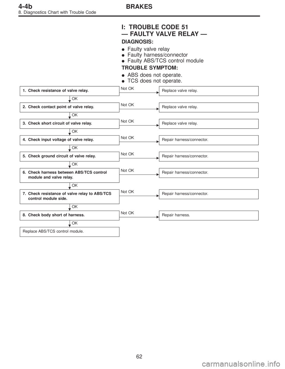
I: TROUBLE CODE 51
—FAULTY VALVE RELAY—
DIAGNOSIS:
�Faulty valve relay
�Faulty harness/connector
�Faulty ABS/TCS control module
TROUBLE SYMPTOM:
�ABS does not operate.
�TCS does not operate.
1. Check resistance of valve relay.
OK
�Not OK
Replace valve relay.
2. Check contact point of valve relay.
OK
�Not OK
Replace valve relay.
3. Check short circuit of valve relay.
OK
�Not OK
Replace valve relay.
4. Check input voltage of valve relay.
OK
�Not OK
Repair harness/connector.
5. Check ground circuit of valve relay.
OK
�Not OK
Repair harness/connector.
6. Check harness between ABS/TCS control
module and valve relay.
OK
�Not OK
Repair harness/connector.
7. Check resistance of valve relay to ABS/TCS
control module side.
OK
�Not OK
Repair harness/connector.
8. Check body short of harness.
OK
�Not OK
Repair harness.
Replace ABS/TCS control module.
�
�
�
�
�
�
�
�
62
4-4bBRAKES
8. Diagnostics Chart with Trouble Code
Page 2274 of 2890
B4M0440
B4M0441
1. CHECK RESISTANCE OF VALVE RELAY.
1) Turn ignition switch OFF.
2) Remove valve relay.
3) Measure resistance between valve relay terminals.
Terminal / Specified resistance:
No. A—B / 90±10Ω
B4M0442
2. CHECK CONTACT POINT OF VALVE RELAY.
1) Turn ignition switch OFF.
2) Remove valve relay.
3) Attach circuit tester probes to terminals as shown in
figure.
4) Measure resistance between respective terminals.
Terminal / Specified resistance:
No. C—E/1Ωor less (When 12 volts applied.)
No. C—E/1MΩor more
(When no voltage is applied.)
No. C—F/1MΩor more
(When 12 volts applied.)
No. C—F/1Ωor less
(When no voltage is applied.)
63
4-4bBRAKES
8. Diagnostics Chart with Trouble Code
Page 2275 of 2890
B4M0443
3. CHECK SHORT CIRCUIT OF VALVE RELAY.
1) Turn ignition switch OFF.
2) Remove valve relay.
3) Measure resistance between valve relay terminals.
Terminal / Specified resistance:
No. B—F/1MΩor more
B4M0444A
4. CHECK INPUT VOLTAGE OF VALVE RELAY.
1) Turn ignition switch OFF.
2) Disconnect valve relay.
3) Measure voltage between valve relay connector and
body.
Connector & terminal / Specified voltage:
(F11) No. 1—body/0V
(F11) No. 3—body / 10—13 V
4) Turn ignition switch ON.
5) Measure voltage between valve relay connector and
body.
Connector & terminal / Specified voltage:
(F11) No. 1—body / 10—13 V
(F11) No. 3—body / 10—13 V
B4M0445A
5. CHECK GROUND CIRCUIT OF VALVE RELAY.
1) Turn ignition switch OFF.
2) Disconnect valve relay.
3) Disconnect ABS/TCS control module.
4) Measure resistance between valve relay connector and
body.
Connector & terminal / Specified resistance:
(F11) No. 6—body / 1Ωor less
64
4-4bBRAKES
8. Diagnostics Chart with Trouble Code

 Turn ignition switch OFF.
2) Disconnect connector from ABS/TCS control module
and TCS valve relay.
3) Meas")
 Turn ignition switch OFF and connect combination
meter connector.
2) Disconnect all connectors from ABS/TCS control mod-
ule.
3) Remove AB")
 Turn ignition switch OFF.
2) Remove valve relay.
3) Measure resistance between valve relay terminals.
Terminal / Specified resistance:
No. A—B")
 Turn ignition switch OFF.
2) Remove valve relay.
3) Measure resistance between valve relay terminals.
Terminal / Specified resistance:
No. B—F/1MΩ")