Page 2346 of 2890
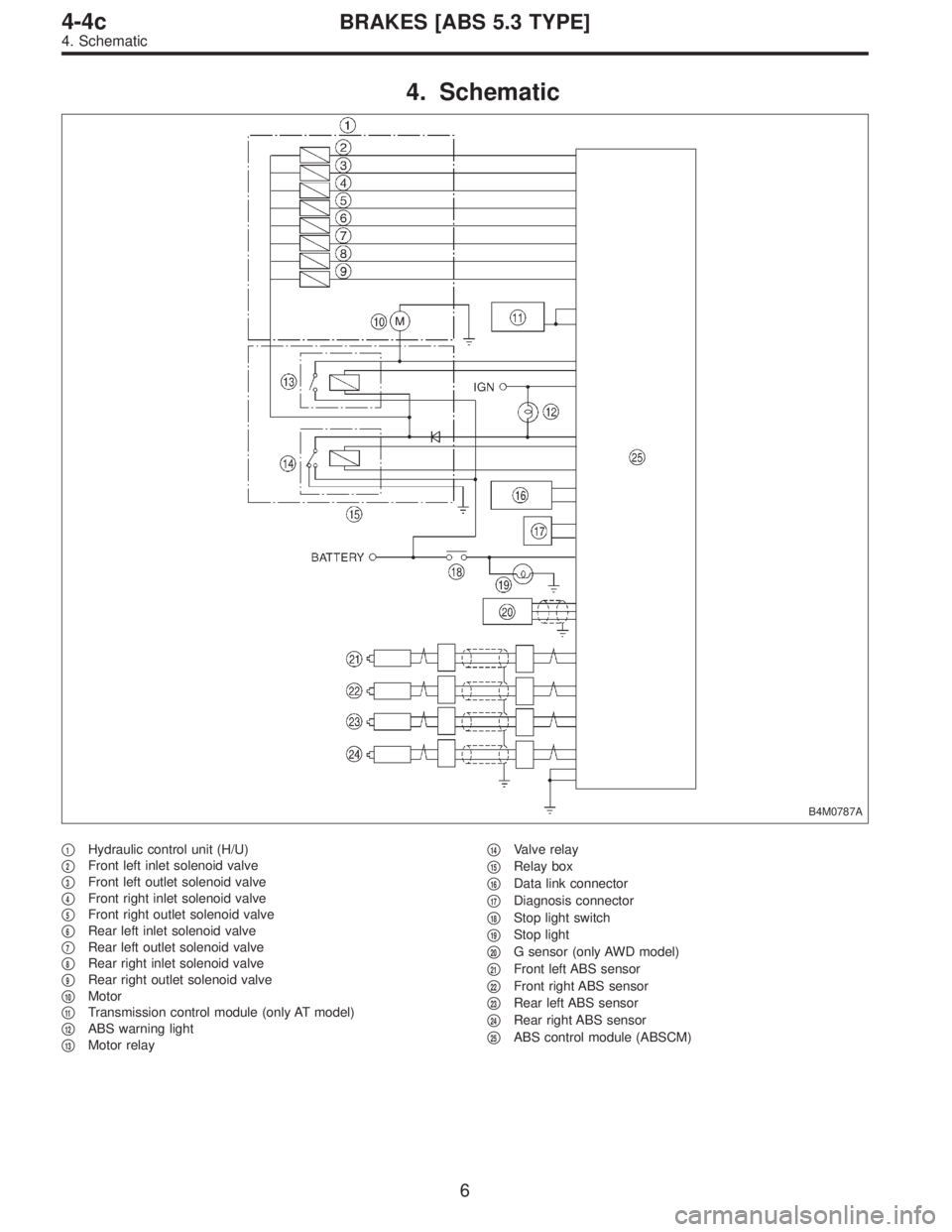
4. Schematic
B4M0787A
�1Hydraulic control unit (H/U)
�
2Front left inlet solenoid valve
�
3Front left outlet solenoid valve
�
4Front right inlet solenoid valve
�
5Front right outlet solenoid valve
�
6Rear left inlet solenoid valve
�
7Rear left outlet solenoid valve
�
8Rear right inlet solenoid valve
�
9Rear right outlet solenoid valve
�
10Motor
�
11Transmission control module (only AT model)
�
12ABS warning light
�
13Motor relay�
14Valve relay
�
15Relay box
�
16Data link connector
�
17Diagnosis connector
�
18Stop light switch
�
19Stop light
�
20G sensor (only AWD model)
�
21Front left ABS sensor
�
22Front right ABS sensor
�
23Rear left ABS sensor
�
24Rear right ABS sensor
�
25ABS control module (ABSCM)
6
4-4cBRAKES [ABS 5.3 TYPE]
4. Schematic
Page 2348 of 2890
Front left wheel 49—19
0.12—1V
(When it is 20 Hz.) Front right wheel 14—15
Rear le")
Contents Terminal No.Input/Output signal
Measured value and measuring conditions
ABS sensor
(Wheel
speed
sensor)Front left wheel 49—19
0.12—1V
(When it is 20 Hz.) Front right wheel 14—15
Rear left wheel 16—17
Rear right wheel 18—46
Hydraulic
control unitSolenoid
valveFront left outlet 51—1
10—13 V when the valve is OFF and
less than 1.5 V when the valve is ON. Front right outlet 3—1
Rear left outlet 4—1
Rear right outlet 50—1
Front left inlet 24—1
Front right inlet 30—1
Rear left inlet 31—1
Rear right inlet 23—1
Relay boxValve relay power supply 27—110—13 V when ignition switch is ON.
Valve relay coil 47—1 Less than 1.5 V when ignition switch is ON.
Motor relay coil 22—1More than 10 V when the ABS control does not operate still
and less than 1.5 V when ABS operates.
Motor monitoring 10—1Less than 1.5 V when the ABS control does not operate still
and more than 10 V when ABS operates.
G sensor
(AWD
model only)power supply 8—45 4.75—5.25 V
ground 45—
output 7—45 2.3±0.2 V when vehicle is in horizontal position.
Stop light switch 36—1Less than 1.5 V when the stop light is OFF and more than
4.5 V when the stop light is ON.
ABS warning light 54—1Less than 1.5 V during 1.5 seconds when ignition switch is
ON, and 10—14 V after 1.5 seconds.
AT ABS signal
(AT model only)12—1Less than 1.5 V when the ABS control does not operate still
and more than 5.5 V when ABS operates.
ABS operation signal monitor 39—1Less than 1.5 V when the ABS control does not operate still
and more than 5.5 V when ABS operates.
Select
monitorData is received. 11—1 Less than 1.5 V when no data is received.
Data is sent. 38—1 4.75—5.25 V when no data is sent.
Diagnosis
connectorTerminal No. 3 5—110—14 V when ignition switch is ON.
Terminal No. 6 13—110—14 V when ignition switch is ON.
Power supply 28—110—14 V when ignition switch is ON.
Grounding line 1—
Grounding line 55—
8
4-4cBRAKES [ABS 5.3 TYPE]
5. Control Module I/O Signal
Page 2354 of 2890
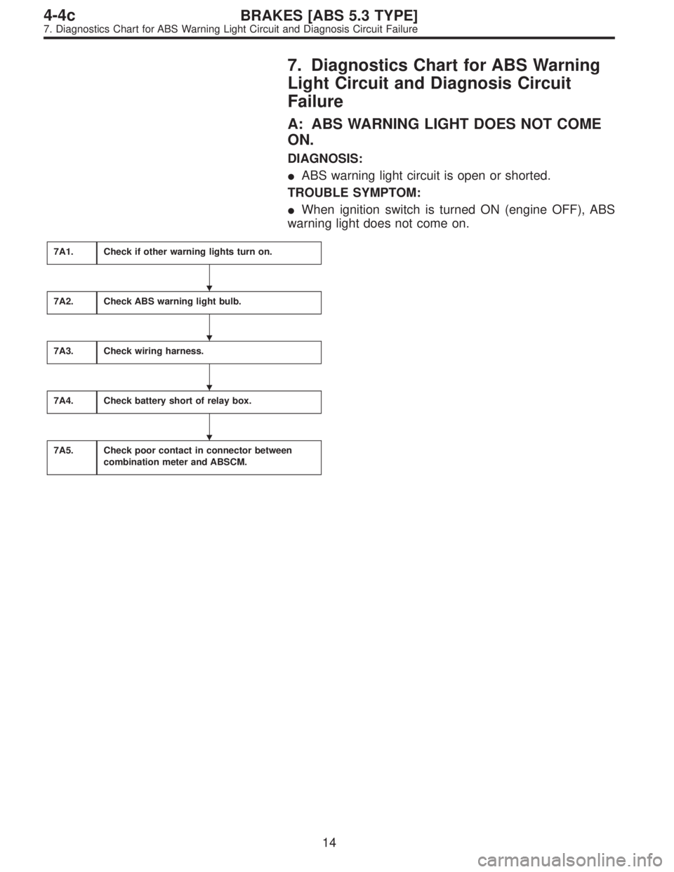
7. Diagnostics Chart for ABS Warning
Light Circuit and Diagnosis Circuit
Failure
A: ABS WARNING LIGHT DOES NOT COME
ON.
DIAGNOSIS:
�ABS warning light circuit is open or shorted.
TROUBLE SYMPTOM:
�When ignition switch is turned ON (engine OFF), ABS
warning light does not come on.
7A1.Check if other warning lights turn on.
7A2.Check ABS warning light bulb.
7A3.Check wiring harness.
7A4.Check battery short of relay box.
7A5.Check poor contact in connector between
combination meter and ABSCM.
�
�
�
�
14
4-4cBRAKES [ABS 5.3 TYPE]
7. Diagnostics Chart for ABS Warning Light Circuit and Diagnosis Circuit Failure
Page 2356 of 2890
7A2
CHECK ABS WARNING LIGHT BULB.
1) Turn ignition switch to OFF.
2) Remove combination meter.
3) Remove ABS warning light bulb from combination
meter.
: Is ABS warning light bulb OK?
: Go to step7A3.
: Replace ABS warning light bulb.
B4M0791A
7A3
CHECK WIRING HARNESS.
1) Disconnect connector from ABSCM.
2) Disconnect connector (F50) from relay box.
3) Turn ignition switch to ON.
4) Measure voltage between connector (F49) and chassis
ground.
: Connector & terminal
(F49) No. 54 (+) — Chassis ground (�):
Is voltage 12 V?
: Go to next step.
: Repair broken wire in harness or connector.
5) Turn ignition switch to OFF.
6) Measure voltage between ABSCM connector (F49) and
chassis ground.
: Connector & terminal
(F49) No. 54 (+) — Chassis ground (�):
Is voltage less than 3 V?
: Go to step7A4.
: Repair battery short of harness.
16
4-4cBRAKES [ABS 5.3 TYPE]
7. Diagnostics Chart for ABS Warning Light Circuit and Diagnosis Circuit Failure
Page 2357 of 2890
B4M0792B
7A4CHECK BATTERY SHORT OF RELAY
BOX.
1) Disconnect connector from relay box.
2) Turn ignition switch to ON.
3) Measure voltage between relay box and chassis
ground.
: Connector & terminal
To (F50) No. 2 (+)—Chassis ground (�):
Is voltage 0 V?
: Go to next step.
: Replace relay box.
4) Turn ignition switch OFF.
5) Measure voltage between relay box and chassis
ground.
: Connector & terminal
To (F50) No. 2 (+)—Chassis ground (�):
Is voltage 0 V?
: Go to step7A5.
: Replace relay box.
7A5CHECK POOR CONTACT IN CONNEC-
TOR BETWEEN COMBINATION METER
AND ABSCM.
: Is there poor contact in connectors between
combination meter and ABSCM?
: Repair connector.
: Replace ABSCM.
17
4-4cBRAKES [ABS 5.3 TYPE]
7. Diagnostics Chart for ABS Warning Light Circuit and Diagnosis Circuit Failure
Page 2358 of 2890
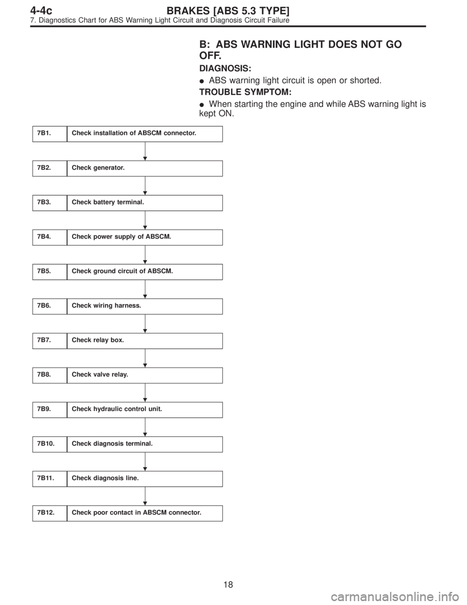
B: ABS WARNING LIGHT DOES NOT GO
OFF.
DIAGNOSIS:
�ABS warning light circuit is open or shorted.
TROUBLE SYMPTOM:
�When starting the engine and while ABS warning light is
kept ON.
7B1.Check installation of ABSCM connector.
7B2.Check generator.
7B3.Check battery terminal.
7B4.Check power supply of ABSCM.
7B5.Check ground circuit of ABSCM.
7B6.Check wiring harness.
7B7.Check relay box.
7B8.Check valve relay.
7B9.Check hydraulic control unit.
7B10.Check diagnosis terminal.
7B11.Check diagnosis line.
7B12.Check poor contact in ABSCM connector.
�
�
�
�
�
�
�
�
�
�
�
18
4-4cBRAKES [ABS 5.3 TYPE]
7. Diagnostics Chart for ABS Warning Light Circuit and Diagnosis Circuit Failure
Page 2361 of 2890
B4M0797A
7B5
CHECK GROUND CIRCUIT OF ABSCM.
1) Turn ignition switch to OFF.
2) Measure resistance between ABSCM connector and
chassis ground.
: Connector & terminal
(F49) No. 1—Chassis ground:
(F49) No. 55—Chassis ground:
Is resistance less than 0.5Ω?
: Go to step7B6.
: Repair ABSCM ground harness.
7B6
CHECK WIRING HARNESS.
1) Disconnect connector (F50) from relay box.
2) Turn ignition switch to ON.
: Does the ABS warning light remain off?
: Go to step7B7.
: Repair front wiring harness.
7B7
CHECK RELAY BOX.
1) Turn ignition switch to OFF.
2) Connect connector (F50) to relay box.
3) Remove valve relay from relay box.
4) Disconnect connector (ABS1) from hydraulic control
unit.
5) Turn ignition switch to ON.
: Does the ABS warning light remain off?
: Go to step7B8.
: Repair relay box and check fuse.
21
4-4cBRAKES [ABS 5.3 TYPE]
7. Diagnostics Chart for ABS Warning Light Circuit and Diagnosis Circuit Failure
Page 2362 of 2890
B4M0798A
B4M0811A
7B8
CHECK VALVE RELAY.
1) Measure resistance between valve relay terminal and
terminal.
: Terminals
No. 30—No. 87:
Is resistance more than 1 MΩ?
No. 30—No. 87a:
Is resistance less than 0.5Ω?
: Go to next step.
: Replace valve relay.
2) Connect battery to valve relay terminal No. 85 and No.
86.
3) Measure resistance between valve relay terminals.
: Terminals
No. 30—No. 87:
Is resistance less than 0.5Ω?
No. 30—No. 87a:
Is resistance more than 1 MΩ?
: Go to step7B9.
: Replace valve relay.
7B9
CHECK HYDRAULIC CONTROL UNIT.
1) Turn ignition switch to OFF.
2) Connect connector (ABS1) to hydraulic control unit.
3) Turn ignition switch to ON.
: Is the ABS warning light off?
: Go to step7B10.
: Replace hydraulic control unit and check fuse No.
19.
22
4-4cBRAKES [ABS 5.3 TYPE]
7. Diagnostics Chart for ABS Warning Light Circuit and Diagnosis Circuit Failure
 Turn ignition switch to OFF.
2) Remove combination meter.
3) Remove ABS warning light bulb from combination
meter.
: Is ABS warning light bulb OK?
: Go to step7A3.")
 Disconnect connector from relay box.
2) Turn ignition switch to ON.
3) Measure voltage between relay box and chassis
ground.
: Connector & terminal
To")
 Turn ignition switch to OFF.
2) Measure resistance between ABSCM connector and
chassis ground.
: Connector & terminal
(F49) No. 1—Chassis ground:
(F49)")
 Measure resistance between valve relay terminal and
terminal.
: Terminals
No. 30—No. 87:
Is resistance more than 1 MΩ?
No. 30—No. 87a:
Is resistance l")