Page 2458 of 2890
LED No. Signal name Display
1 Stop light switch B1
2 Valve relay signal VR
3 Motor relay signal MR
4 AT ABS signal AT
5——
6 ABS warning light AW
7 Valve relay monitor VM
8 Motor relay monitor MM
9 CCM signal CM
10——
B1 VR MR AT—
AW VM MM CM—
1
2345
678910
I: MODE FA0
—ON↔OFF SIGNAL—
Requirement for LED“ON”
LED No. 1 Stop light switch is turned ON. (With brake
pedal depressed.)
LED No. 2 Valve relay is turned OFF.
LED No. 3 Motor relay is turned ON.
LED No. 4 ABS control operates.
LED No. 6 ABS warning light is ON.
LED No. 7 Valve relay is turned OFF.
LED No. 8 Motor relay is turned ON.
LED No. 9 ABS control operates.
11 8
4-4cBRAKES [ABS 5.3 TYPE]
9. Select Monitor Function Mode
Page 2462 of 2890
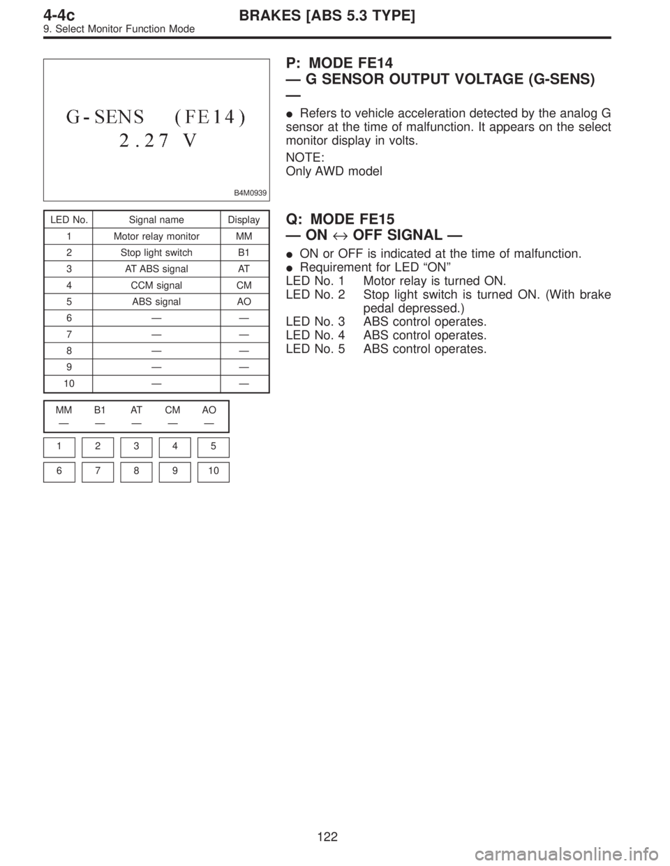
B4M0939
P: MODE FE14
—G SENSOR OUTPUT VOLTAGE (G-SENS)
—
�Refers to vehicle acceleration detected by the analog G
sensor at the time of malfunction. It appears on the select
monitor display in volts.
NOTE:
Only AWD model
LED No. Signal name Display
1 Motor relay monitor MM
2 Stop light switch B1
3 AT ABS signal AT
4 CCM signal CM
5 ABS signal AO
6——
7——
8——
9——
10——
MM B1 AT CM AO
—————
1
2345
678910
Q: MODE FE15
—ON↔OFF SIGNAL—
�ON or OFF is indicated at the time of malfunction.
�Requirement for LED“ON”
LED No. 1 Motor relay is turned ON.
LED No. 2 Stop light switch is turned ON. (With brake
pedal depressed.)
LED No. 3 ABS control operates.
LED No. 4 ABS control operates.
LED No. 5 ABS control operates.
122
4-4cBRAKES [ABS 5.3 TYPE]
9. Select Monitor Function Mode
Page 2464 of 2890
![SUBARU LEGACY 1996 Service Repair Manual B: LIST OF TROUBLE CODE
Code Display screen (FB1) Contents of diagnosis Ref. to
—ERROR 3 (1) Select monitor communication failure 4-4c [T10C0]
11 NO TROUBLEAlthough no trouble appears on the select](/manual-img/17/57433/w960_57433-2463.png "SUBARU LEGACY 1996 Service Repair Manual B: LIST OF TROUBLE CODE
Code Display screen (FB1) Contents of diagnosis Ref. to
—ERROR 3 (1) Select monitor communication failure 4-4c [T10C0]
11 NO TROUBLEAlthough no trouble appears on the select")
B: LIST OF TROUBLE CODE
Code Display screen (FB1) Contents of diagnosis Ref. to
—ERROR 3 (1) Select monitor communication failure 4-4c [T10C0]
11 NO TROUBLEAlthough no trouble appears on the select monitor display, the ABS
warning light remains on.4-4c [T10D0]
21 FR. SS HARD Open circuit or input voltage too high of FR sensor 4-4c [T10E0]
22 FR. SS SOFT Abnormal ABS sensor signal of FR sensor 4-4c [T10I0]
23 FL. SS HARD Open circuit or input voltage too high of FL sensor 4-4c [T10F0]
24 FL. SS SOFT Abnormal ABS sensor signal of FL sensor 4-4c [T10J0]
25 RR. SS HARD Open circuit or input voltage too high of RR sensor 4-4c [T10G0]
26 RR. SS SOFT Abnormal ABS sensor signal of RR sensor 4-4c [T10K0]
27 RL. SS HARD Open circuit or input voltage too high of RL sensor 4-4c [T10H0]
28 RL. SS SOFT Abnormal ABS sensor signal of RL sensor 4-4c [T10L0]
29 EITHER. SS SOFT Abnormal ABS sensor signal (any one of four) 4-4c [T10M0]
31 FR. EV VALVE Abnormal FR inlet valve 4-4c [T10N0]
32 FR. AV VALVE Abnormal FR outlet valve 4-4c [T10R0]
33 FL. EV VALVE Abnormal FL inlet valve 4-4c [T10O0]
34 FL. AV VALVE Abnormal FL outlet valve 4-4c [T10S0]
35 RR. EV VALVE Abnormal RR inlet valve 4-4c [T10P0]
36 RR. AV VALVE Abnormal RR outlet valve 4-4c [T10T0]
37 RL. EV VALVE Abnormal RL inlet valve 4-4c [T10Q0]
38 RL. AV VALVE Abnormal RL outlet valve 4-4c [T10U0]
41 ECU Abnormal ABSCM 4-4c [T10V0]
42 LOW VOLTAGE Source voltage is low. 4-4c [T10W0]
44CCM LINE A combination of AT control abnormals (ABS not in control) 4-4c [T10X0]
CCM OPEN A combination of AT control abnormals (ABS in control) 4-4c [T10Y0]
46GS POWER OVER G sensor line voltage too high 4-4c [T10Z0]
GS POWER LOW G sensor line voltage too low 4-4c [T10AA0]
51V. RELAY Abnormal valve relay 4-4c [T10AB0]
V. RELAY ON Valve relay ON failure 4-4c [T10AC0]
52M. RELAY OPEN Open circuit of motor relay 4-4c [T10AD0]
M. RELAY ON Motor relay ON failure 4-4c [T10AE0]
MOTOR Abnormal motor 4-4c [T10AF0]
54 BLS Abnormal stop light switch 4-4c [T10AG0]
56G SENSOR LINE Open or short circuit of G sensor 4-4c [T10AH0]
G SENSOR +B Battery short of G sensor 4-4c [T10AI0]
G SENSOR Hµ Abnormal G sensor high µ output 4-4c [T10AJ0]
G SENSOR STICK G sensor output is stuck. 4-4c [T10AK0]
NOTE:
High µ means high friction coefficient against road sur-
face.
124
4-4cBRAKES [ABS 5.3 TYPE]
10. Diagnostics Chart with Select Monitor
Page 2470 of 2890
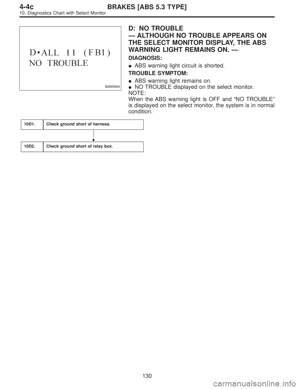
B4M0944
D: NO TROUBLE
—ALTHOUGH NO TROUBLE APPEARS ON
THE SELECT MONITOR DISPLAY, THE ABS
WARNING LIGHT REMAINS ON.—
DIAGNOSIS:
�ABS warning light circuit is shorted.
TROUBLE SYMPTOM:
�ABS warning light remains on.
�NO TROUBLE displayed on the select monitor.
NOTE:
When the ABS warning light is OFF and“NO TROUBLE”
is displayed on the select monitor, the system is in normal
condition.
10D1.Check ground short of harness.
10D2.Check ground short of relay box.
�
130
4-4cBRAKES [ABS 5.3 TYPE]
10. Diagnostics Chart with Select Monitor
Page 2472 of 2890
10D1
CHECK GROUND SHORT OF HARNESS.
1) Turn ignition switch to OFF.
2) Disconnect connector from ABSCM.
3) Disconnect connector (F50) from relay box.
4) Turn ignition switch to ON.
: Does the ABS warning light remain OFF?
: Go to step10D2.
: Repair harness between ABSCM, relay box ABS
warning light.
10D2CHECK GROUND SHORT OF RELAY
BOX.
1) Turn ignition switch to OFF.
2) Connect connector (F50) to relay box.
3) Disconnect connector (ABS1) from hydraulic unit.
4) Remove valve relay from relay box.
5) Turn ignition switch to ON.
: Does the ABS warning light remain OFF?
: Replace ABSCM.
: Replace relay box.
132
4-4cBRAKES [ABS 5.3 TYPE]
10. Diagnostics Chart with Select Monitor
Page 2543 of 2890
B4M0968
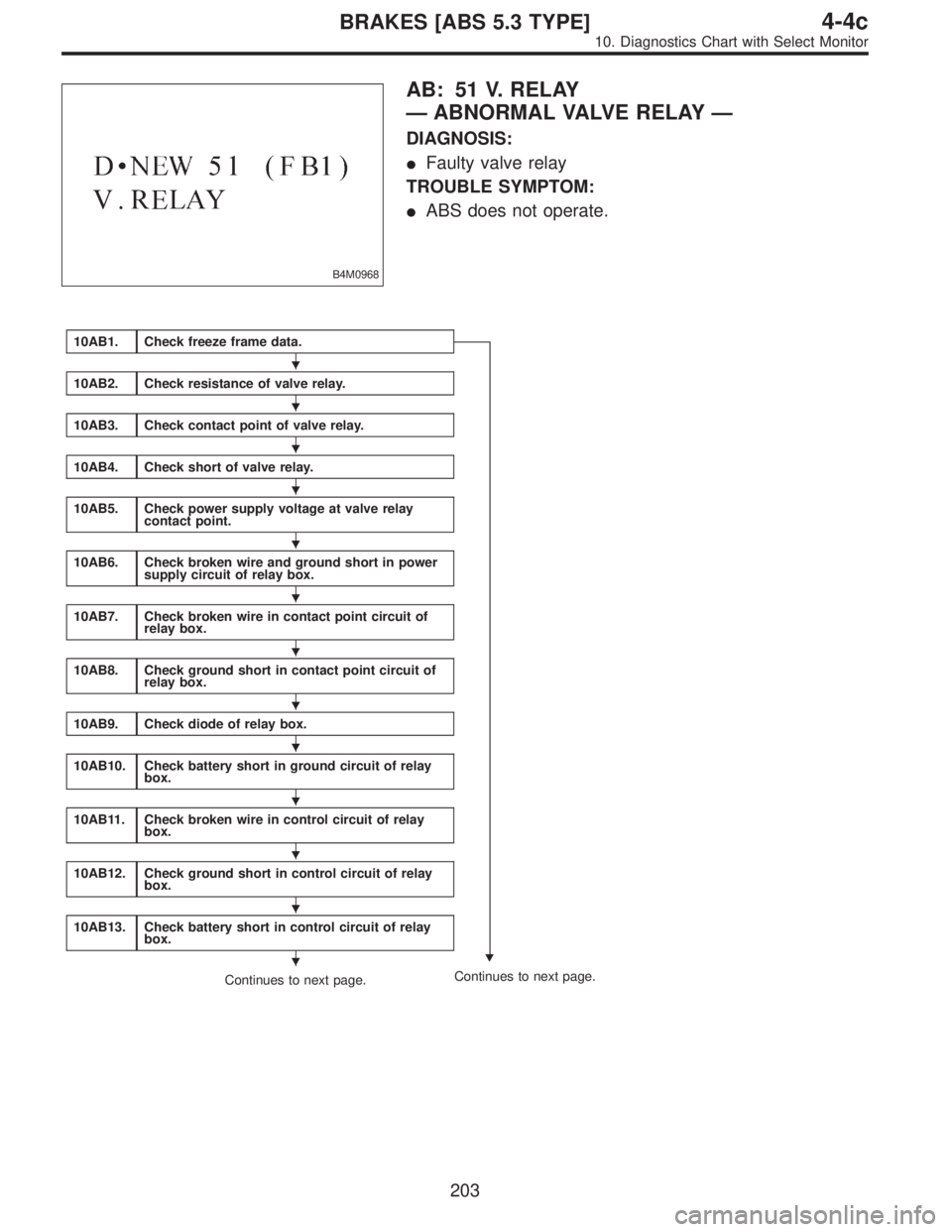
AB: 51 V. RELAY
—ABNORMAL VALVE RELAY—
DIAGNOSIS:
�Faulty valve relay
TROUBLE SYMPTOM:
�ABS does not operate.
10AB1.Check freeze frame data.
�
10AB2.Check resistance of valve relay.
10AB3.Check contact point of valve relay.
10AB4.Check short of valve relay.
10AB5.Check power supply voltage at valve relay
contact point.
10AB6.Check broken wire and ground short in power
supply circuit of relay box.
10AB7.Check broken wire in contact point circuit of
relay box.
10AB8.Check ground short in contact point circuit of
relay box.
10AB9.Check diode of relay box.
10AB10.Check battery short in ground circuit of relay
box.
10AB11.Check broken wire in control circuit of relay
box.
10AB12.Check ground short in control circuit of relay
box.
10AB13.Check battery short in control circuit of relay
box.
Continues to next page.Continues to next page.
�
�
�
�
�
�
�
�
�
�
�
�
�
203
4-4cBRAKES [ABS 5.3 TYPE]
10. Diagnostics Chart with Select Monitor
Page 2544 of 2890
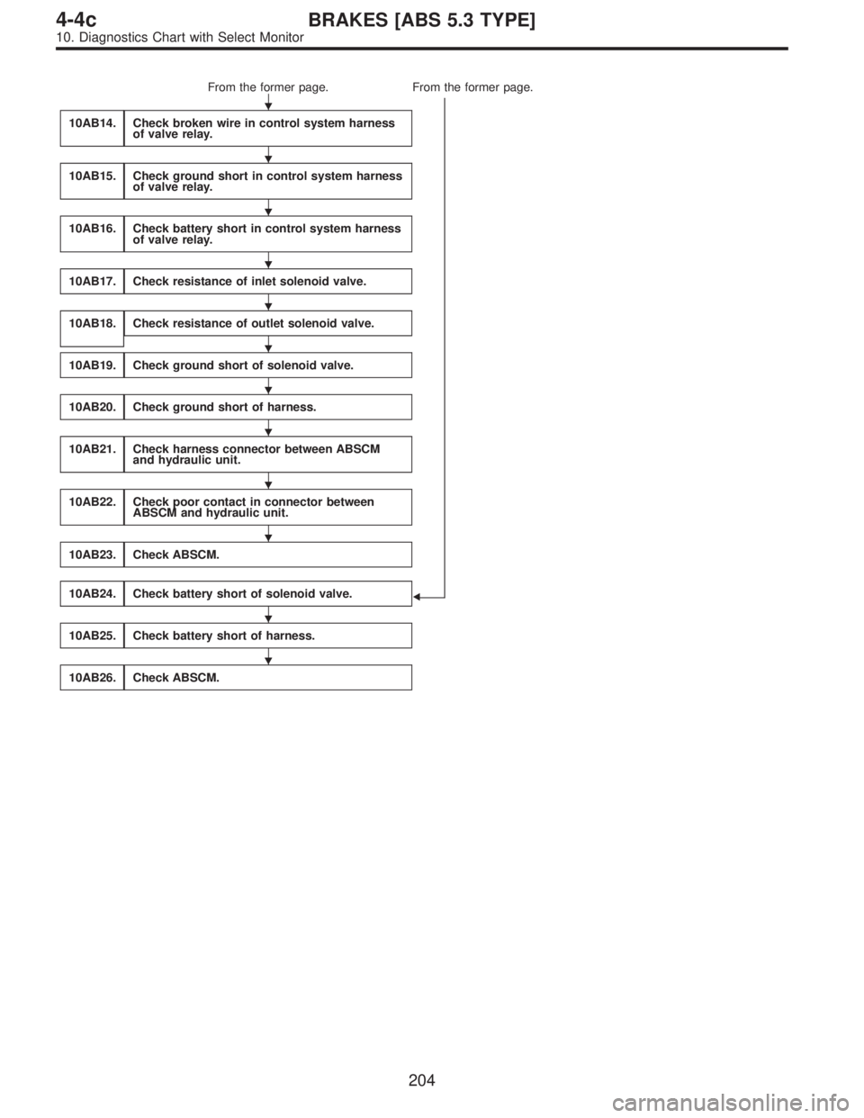
From the former page. From the former page.
�
10AB14.Check broken wire in control system harness
of valve relay.
10AB15.Check ground short in control system harness
of valve relay.
10AB16.Check battery short in control system harness
of valve relay.
10AB17.Check resistance of inlet solenoid valve.
10AB18.Check resistance of outlet solenoid valve.
10AB19.Check ground short of solenoid valve.
10AB20.Check ground short of harness.
10AB21.Check harness connector between ABSCM
and hydraulic unit.
10AB22.Check poor contact in connector between
ABSCM and hydraulic unit.
10AB23.Check ABSCM.
10AB24.Check battery short of solenoid valve.
10AB25.Check battery short of harness.
10AB26.Check ABSCM.
�
�
�
�
�
�
�
�
�
�
�
�
204
4-4cBRAKES [ABS 5.3 TYPE]
10. Diagnostics Chart with Select Monitor
Page 2546 of 2890
 Turn ignition switch to OFF.
2) Remove valve relay from relay box.
3) Measure resistance between valve relay terminals.
: Terminals
No. 85—No. 86
I")
B4M0858A
10AB2
CHECK RESISTANCE OF VALVE RELAY.
1) Turn ignition switch to OFF.
2) Remove valve relay from relay box.
3) Measure resistance between valve relay terminals.
: Terminals
No. 85—No. 86
Is resistance 103±10Ω?
: Go to step10AB3.
: Replace valve relay.
B4M0811A
10AB3CHECK CONTACT POINT OF VALVE
RELAY.
1) Connect battery to valve relay terminals No. 85 and No.
86.
2) Measure resistance between valve relay terminals.
: Terminals
No. 30—No. 87
Is resistance less than 0.5Ω?
: Go to next.
: Replace valve relay.
: Terminals
No. 30—No. 87a
Is resistance more than 1 MΩ?
: Go to next step.
: Replace valve relay.
B4M0798A
3) Disconnect battery from valve relay terminals.
4) Measure resistance between valve relay terminals.
: Terminals
No. 30—No. 87
Is resistance more than 1 MΩ?
: Go to next.
: Replace valve relay.
: Terminals
No. 30—No. 87a
Is resistance less than 0.5Ω?
: Go to step10AB4.
: Replace valve relay.
206
4-4cBRAKES [ABS 5.3 TYPE]
10. Diagnostics Chart with Select Monitor

 Turn ignition switch to OFF.
2) Disconnect connector from ABSCM.
3) Disconnect connector (F50) from relay box.
4) Turn ignition switch to ON.
: Does the ABS warn")