Page 2571 of 2890
 Disconnect connector from ABSCM.
2) Turn ignition switch to ON.
3) Measure voltage between motor relay installing point
and chassi")
B4M0897
10AD11CHECK BATTERY SHORT IN CONTROL
CIRCUIT OF RELAY BOX.
1) Disconnect connector from ABSCM.
2) Turn ignition switch to ON.
3) Measure voltage between motor relay installing point
and chassis ground.
: Connector & terminal
Motor relay installing point No. 85 (+)—
Chassis ground (�)
Motor relay installing point No. 86 (+)—
Chassis ground (�).
Is voltage 0 V?
: Go to next step.
: Replace relay box and check all fuses.
4) Turn ignition switch to OFF.
5) Measure voltage between motor relay installing point
and chassis ground.
: Connector & terminal
Motor relay installing point No. 85 (+)—
Chassis ground
Motor relay installing point No. 86 (+)—
Chassis ground (�)
Is voltage 0 V?
: Go to step10AD12.
: Replace relay box and check all fuses.
B4M0898B
10AD12CHECK BROKEN WIRE IN MONITOR
SYSTEM HARNESS.
1) Connect between terminals No. 10 and No. 1 of
ABSCM connector (F49) with a lead wire.
2) Measure resistance between relay box connector and
chassis ground.
: Connector & terminal
(F50) No. 6—Chassis ground
Is resistance less than 0.5Ω?
: Go to step10AD13.
: Repair harness connector between ABSCM and
relay box.
231
4-4cBRAKES [ABS 5.3 TYPE]
10. Diagnostics Chart with Select Monitor
Page 2572 of 2890
B4M0899A
10AD13CHECK BROKEN WIRE IN RELAY CON-
TROL SYSTEM HARNESS.
1) Connect valve relay and motor relay to relay box.
2) Connect connector (F50) to relay box.
3) Connect connector to hydraulic unit.
4) Measure resistance between ABSCM connector and
chassis ground.
: Connector & terminal
(F49) No. 22—Chassis ground
Is resistance 80±10Ω?
: Go to step10AD14.
: Repair harness connector between ABSCM and
relay box.
B4M0900A
10AD14CHECK GROUND SHORT BETWEEN
RELAY BOX AND ABSCM.
1) Disconnect connector (F50) from relay box.
2) Measure resistance between ABSCM connector and
chassis ground.
: Connector & terminal
(F49) No. 22—Chassis ground
(F49) No. 10—Chassis ground
Is resistance more than 1 MΩ?
: Go to step10AD15.
: Repair harness between ABSCM and relay box.
Check fuse No. 19 and SBF6.
232
4-4cBRAKES [ABS 5.3 TYPE]
10. Diagnostics Chart with Select Monitor
Page 2573 of 2890
 Turn ignition switch to ON.
2) Measure voltage between ABSCM and chassis ground.
: Connector & terminal
(F49) No. 22 (+)—Chassis gr")
B4M0901A
10AD15CHECK BATTERY SHORT BETWEEN
RELAY BOX AND ABSCM.
1) Turn ignition switch to ON.
2) Measure voltage between ABSCM and chassis ground.
: Connector & terminal
(F49) No. 22 (+)—Chassis ground (�)
(F49) No. 10 (+)—Chassis ground (�)
Is voltage 0 V?
: Go to next step.
: Repair harness between relay box and ABSCM.
Check fuse SBF6.
3) Turn ignition switch to OFF.
4) Measure voltage between ABSCM and chassis ground.
: Connector & terminal
(F49) No. 22 (+)—Chassis ground (�)
(F49) No. 10 (+)—Chassis ground (�)
Is voltage 0 V?
: Go to step10AD16.
: Repair harness between relay box and ABSCM.
Check fuse SBF6.
B4M0902A
10AD16CHECK GROUND SHORT AT ABSCM
MONITOR TERMINAL.
Measure resistance between ABSCM terminals.
: Connector & terminal
To (F49) No. 10—No. 1
Is resistance more than 1 MΩ?
: Go to step10AD17.
: Replace ABSCM.
B4M0904A
10AD17CHECK ABSCM MOTOR DRIVE TERMI-
NAL.
1) Disconnect connector cover from ABSCM connector.
2) Connect all connectors.
3) Measure voltage between ABSCM connector terminals.
4) Operate the check sequence.
: Connector & terminals
(F49) No. 22 (+)—No.1(�)
Does the voltage drop from 10—13Vto
less than 1.5 V, and rise to 10—13 V again
when carrying out the check sequence?
: Go to step10AD18.
: Replace ABSCM.
233
4-4cBRAKES [ABS 5.3 TYPE]
10. Diagnostics Chart with Select Monitor
Page 2574 of 2890
![SUBARU LEGACY 1996 Service Repair Manual B4M0905A
10AD18
CHECK MOTOR OPERATION.
1) Measure voltage between ABSCM connector terminal.
2) Operate the check sequence. <Ref. to 4-4 [W22D1].>
: Connector & terminals
(F49) No. 10 (+)—No.1(�)
Doe](/manual-img/17/57433/w960_57433-2573.png "SUBARU LEGACY 1996 Service Repair Manual B4M0905A
10AD18
CHECK MOTOR OPERATION.
1) Measure voltage between ABSCM connector terminal.
2) Operate the check sequence. <Ref. to 4-4 [W22D1].>
: Connector & terminals
(F49) No. 10 (+)—No.1(�)
Doe")
B4M0905A
10AD18
CHECK MOTOR OPERATION.
1) Measure voltage between ABSCM connector terminal.
2) Operate the check sequence.
: Connector & terminals
(F49) No. 10 (+)—No.1(�)
Does the voltage raise from less than 1.5 V
to 10—13 V, and return to less than 1.5 V
again when carrying out the check
sequence?
Can motor revolution noise (buzz) be heard
when carrying out the check sequence?
: Go to step10AD19.
: Replace hydraulic unit.
10AD19CHECK POOR CONTACT IN CONNEC-
TOR BETWEEN HYDRAULIC UNIT,
RELAY BOX AND ABSCM.
: Is there poor contact in connector between
hydraulic unit, relay box and ABSCM?
: Repair connector.
: Go to step10AD20.
10AD20
CHECK ABSCM.
1) Connect all connectors.
2) Erase the memory.
3) Perform inspection mode.
4) Read out the trouble code.
: Is the same trouble code as in the current
diagnosis still being output?
: Replace ABSCM.
: Go to next.
: Are other trouble codes being output?
: Proceed with the diagnosis corresponding to the
trouble code.
: A temporary poor contact.
234
4-4cBRAKES [ABS 5.3 TYPE]
10. Diagnostics Chart with Select Monitor
Page 2575 of 2890
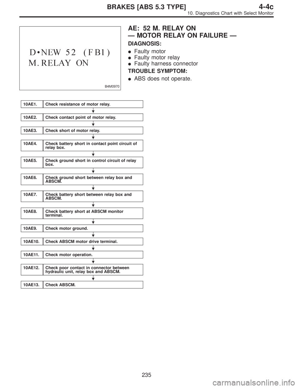
B4M0970
AE: 52 M. RELAY ON
—MOTOR RELAY ON FAILURE—
DIAGNOSIS:
�Faulty motor
�Faulty motor relay
�Faulty harness connector
TROUBLE SYMPTOM:
�ABS does not operate.
10AE1.Check resistance of motor relay.
10AE2.Check contact point of motor relay.
10AE3.Check short of motor relay.
10AE4.Check battery short in contact point circuit of
relay box.
10AE5.Check ground short in control circuit of relay
box.
10AE6.Check ground short between relay box and
ABSCM.
10AE7.Check battery short between relay box and
ABSCM.
10AE8.Check battery short at ABSCM monitor
terminal.
10AE9.Check motor ground.
10AE10.Check ABSCM motor drive terminal.
10AE11.Check motor operation.
10AE12.Check poor contact in connector between
hydraulic unit, relay box and ABSCM.
10AE13.Check ABSCM.
�
�
�
�
�
�
�
�
�
�
�
�
235
4-4cBRAKES [ABS 5.3 TYPE]
10. Diagnostics Chart with Select Monitor
Page 2576 of 2890
WIRING DIAGRAM:
B4M1049
B4M0886A
10AE1
CHECK RESISTANCE OF MOTOR RELAY.
1) Turn ignition switch to OFF.
2) Remove motor relay from relay box.
3) Measure resistance between motor relay terminals.
: Terminals
No. 85—No. 86
Is resistance 80±10Ω?
: Go to step10AE2.
: Replace motor relay.
236
4-4cBRAKES [ABS 5.3 TYPE]
10. Diagnostics Chart with Select Monitor
Page 2577 of 2890
B4M0887A
10AE2CHECK CONTACT POINT OF MOTOR
RELAY.
1) Connect battery to motor relay terminals No. 85 and No.
86.
2) Measure resistance between motor relay terminals.
: Terminals
No. 30—No. 87
Is resistance less than 0.5Ω?
: Go to next step.
: Replace motor relay.
B4M0888A
3) Disconnect battery from motor relay terminals.
4) Measure resistance between motor relay terminals.
: Terminals
No. 30—No. 87
Is resistance more than 1 MΩ?
: Go to step10AE3.
: Replace motor relay.
B4M0889A
10AE3
CHECK SHORT OF MOTOR RELAY.
Measure resistance between motor relay terminals.
: Terminals
No. 85—No. 30
No. 85—No. 87
Is resistance more than 1 MΩ?
: Go to step10AE4.
: Replace motor relay.
237
4-4cBRAKES [ABS 5.3 TYPE]
10. Diagnostics Chart with Select Monitor
Page 2578 of 2890
 Disconnect connector from ABSCM.
2) Disconnect connector (ABS1) from hydraulic unit.
3) Turn ignition switch to ON.
4) Measu")
B4M0793A
10AE4CHECK BATTERY SHORT IN CONTACT
POINT CIRCUIT OF RELAY BOX.
1) Disconnect connector from ABSCM.
2) Disconnect connector (ABS1) from hydraulic unit.
3) Turn ignition switch to ON.
4) Measure voltage between relay box connector and
chassis ground.
: Connector & terminal
(ABS1) No. 1 (+)—Chassis ground (�)
Is voltage 0 V?
: Go to next step.
: Replace relay box.
5) Turn ignition switch to OFF.
6) Measure voltage between relay box connector and
chassis ground.
: Connector & terminal
(ABS1) No. 1 (+)—Chassis ground (�)
Is voltage 0 V?
: Go to step10AE5.
: Replace relay box.
B4M1032
10AE5CHECK GROUND SHORT IN CONTROL
CIRCUIT OF RELAY BOX.
1) Disconnect connector (F50) from relay box.
2) Measure resistance between relay box and chassis
ground.
: Connector & terminal
Motor relay installing point No. 85—Chas-
sis ground
Motor relay installing point No. 86—Chas-
sis ground
Is resistance more than 1 MΩ?
: Go to step10AE6.
: Replace relay box. Check fuse No. 19.
238
4-4cBRAKES [ABS 5.3 TYPE]
10. Diagnostics Chart with Select Monitor
 Connect valve relay and motor relay to relay box.
2) Connect connector (F50) to relay box.
3) Connect connector to hydraulic unit")
 Turn ignition switch to OFF.
2) Remove motor relay from relay box.
3) Measure resistance between motor relay terminals.
: Ter")
 Connect battery to motor relay terminals No. 85 and No.
86.
2) Measure resistance between motor relay terminals.
: Terminals
No. 30—No. 87
Is res")