Page 2725 of 2890
B6M0198
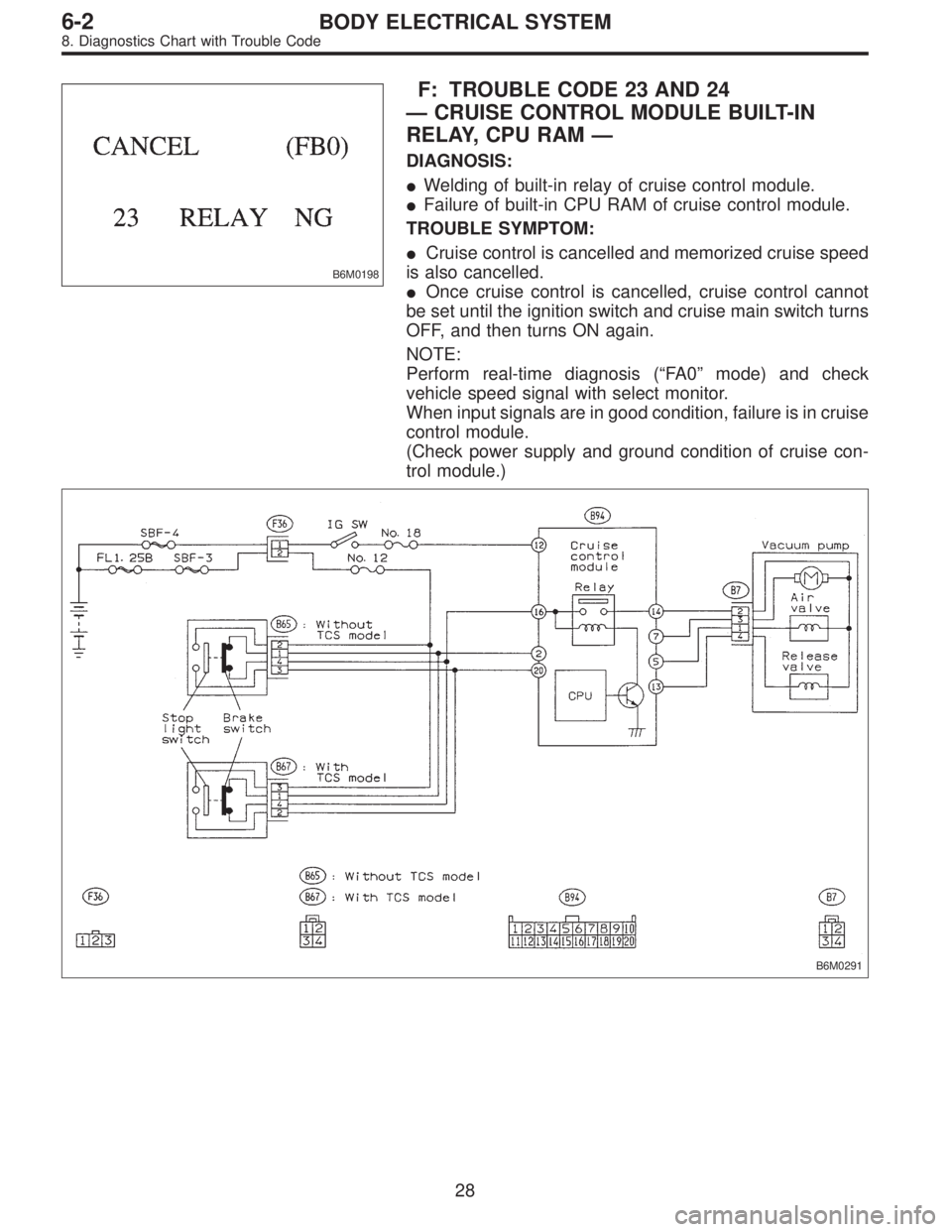
F: TROUBLE CODE 23 AND 24
—CRUISE CONTROL MODULE BUILT-IN
RELAY, CPU RAM—
DIAGNOSIS:
�Welding of built-in relay of cruise control module.
�Failure of built-in CPU RAM of cruise control module.
TROUBLE SYMPTOM:
�Cruise control is cancelled and memorized cruise speed
is also cancelled.
�Once cruise control is cancelled, cruise control cannot
be set until the ignition switch and cruise main switch turns
OFF, and then turns ON again.
NOTE:
Perform real-time diagnosis (“FA 0”mode) and check
vehicle speed signal with select monitor.
When input signals are in good condition, failure is in cruise
control module.
(Check power supply and ground condition of cruise con-
trol module.)
B6M0291
28
6-2BODY ELECTRICAL SYSTEM
8. Diagnostics Chart with Trouble Code
Page 2736 of 2890
10) Relays are classified as normally-open or normally-
closed.
The normally-closed relay has one or more contacts.
The wiring diagram shows the relay mode when the ener-
gizing circuit is OFF.
G6M0204
Key to symbols:
�→: Current flows.
X→: Current does not flow.
6
6-3WIRING DIAGRAM
1. General Description
Page 2738 of 2890

2. Basic Diagnostics Procedures
The most important purpose of diagnostics is to determine
which part is malfunctioning quickly, to save time and labor.
A: IDENTIFICATION OF TROUBLE SYMPTOM
Determine what the problem is based on the symptom.
B: PROBABLE CAUSE OF TROUBLE
Look at the wiring diagram and check the system’s circuit.
Then check the switch, relay, fuse, ground, etc.
C: LOCATION AND REPAIR OF TROUBLE
1) Using the diagnostics narrow down the causes.
2) If necessary, use a voltmeter, ohmmeter, etc.
3) Before replacing certain component parts (switch, relay,
etc.), check the power supply, ground, for open wiring
harness, poor connectors, etc. If no problems are
encountered, check the component parts.
D: CONFIRMATION OF SYSTEM OPERATION
After repairing, ensure that the system operates properly.
G6M0206
E: INSPECTION
1. VOLTAGE MEASUREMENT
1) Using a voltmeter, connect the negative lead to a good
ground point or negative battery terminal and the positive
lead to the connector or component terminal.
2) Contact the positive probe of the voltmeter on connec-
tor (A).
The voltmeter will indicate a voltage.
3) Shift the positive probe to connector (B). The voltmeter
will indicate no voltage.
With test set-up held as it is, turn switch ON. The voltme-
ter will indicate a voltage and, at the same time, the light
will come on.
4) The circuit is in good order. If a problem such as a lamp
failing to light occurs, use the procedures outlined above to
track down the malfunction.
8
6-3WIRING DIAGRAM
2. Basic Diagnostics Procedures
Page 2742 of 2890
G6M0213
5) Some connectors are provided with a lock. One type of
such a connector is disconnected by pushing the lock, and
the other, by moving the lock up. In either type the lock
shape must be identified before attempting to disconnect
the connector.
To connect, insert the connector until it snaps and confirm
that it is tightly connected.
G6M0214
6) When checking continuity between connector terminals,
or measuring voltage across the terminal and ground,
always contact tester probe(s) on terminals from the wiring
connection side. If the probe is too thick to gain access to
the terminal, use“mini”test leads.
To check water-proof connectors (which are not accessible
from the wiring side), contact test probes on the terminal
side being careful not to bend or damage the terminals.
7) Sensors, relays, electrical unit, etc., are sensitive to
strong impacts.
Handle them with care so that they are not dropped or
mishandled.
12
6-3WIRING DIAGRAM
3. Working Precautions
Page 2743 of 2890
4. How to Use Wiring Diagram
B6M0213A
A: RELAY
A symbol used to indicate a relay.
B: CONNECTOR-1
The sketch of the connector indicates the one-
pole types.
C: WIRING CONNECTION
Some wiring diagrams are indicated in foldouts
for convenience. Wiring destinations are indi-
cated where necessary by corresponding sym-
bols (as when two pages are needed for clear
indication).
D: FUSE No. & RATING
The“FUSE No. & RATING”corresponds that
used in the fuse box (main fuse box, and joint
box).
E: CONNECTOR-2
1. Each connector is indicated by a symbol.
2. Each terminal number is indicated in the cor-
responding wiring diagram in an abbreviated
form.
3. For example, terminal number“C2”refers to
No. 2 terminal of connector (C:F41) shown in
the connector sketch.
13
6-3WIRING DIAGRAM
4. How to Use Wiring Diagram
Page 2750 of 2890

MB-2 Power window circuit breaker
MB-3Engine control module
Fuel pump relay
Main relay
OBD-II service connector
MB-4 A/C relay holder
MB-5 He")
No. Load
MB-1Fuse holder (Rear power supply & seat
heater)
MB-2 Power window circuit breaker
MB-3Engine control module
Fuel pump relay
Main relay
OBD-II service connector
MB-4 A/C relay holder
MB-5 Headlight alarm relay (with security)
MB-6 Headlight LH
MB-7Daytime running light control module
Diode (Lighting)
Diode (Security)
Lighting switch
MB-8Combination meter
Front fog light switch
Headlight RH
Front fog light relay
MB-9Door lock timer
Headlight alarm relay
Interrupt relay
Radio
Security control module
Security indicator light
Spot light
Room light
Step light
Combination meter
Luggage room light
Trailer connector
Trunk room light
MB-10 A/C relay holder
SBF-6ABS relay box
TCS motor relay
SBF-7 TCS valve relay
ALT-1Combination meter
Daytime running light control module
Diode (TCS)
IG Headlight alarm relay
STCruise control module
Engine control module
Inhibitor switch (AT)
Interrupt relay
Starter interlock relay (MT)
FB-1Front washer motor
Rear washer motor
FB-2 Diode (A/C)
FB-3A/C relay holder
Sub fan motor
FB-4Engine control module
Fuel pump relay
Ignition coil
Transmission control module
FB-5 ABS relay boxNo. Load
FB-6Side marker light LH
Side marker light RH
FB-7 Door lock timer
FB-9 Hazard switch
FB-10AT shift lock control module
Key warning switch
Power antenna
FB-11 Radio
FB-12 Cigarette lighter socket
FB-13Mirror heater
Rear power supply relay
Remote control rearview mirror switch
Security control module
Vanity mirror illumination light
FB-14AT shift lock control module
Combination switch
Front wiper motor
Rear wiper motor
Rear wiper relay
FB-15ABS/TCS control module
Transmission control module
FB-16Rear defogger
Rear defogger condenser
Rear defogger switch
FB-17 Rear defogger switch
FB-18AT shift lock control module
Back-up light switch (MT)
Inhibitor switch (AT)
FB-19 Hazard switch
FB-20A/C switch
Combination meter
Mode control panel
TCS off switch
FB-21 Combination meter (Airbag)
FB-22Blower motor relay
Check connector
Daytime running light control module
Daytime running light relay
FRESH/RECIRC actuator
Hi-beam relay
Power window and sunroof relay
Seat belt timer
FB-23 Airbag control module
20
6-3WIRING DIAGRAM
6. Wiring Diagram
Page 2751 of 2890
No. Load
FB-24 Airbag control module
FB-25 Lighting switch
FB-26 Parking switch
FB-27 Parking switch
FB-28 Illumination light
FB-29 Illumination light
FB-30Pedal stroke switch
Stop light switch
Stop & brake switch
FB-31 Horn relay
FB-32 Blower motor relay
FB-33 Parking switch
FB-34License plate light
Rear combination light LH
Rear combination light RH
Rear finisher light LH
Rear finisher light RH
FB-35ABS control module
ABS/TCS control module
TCS valve relay
Cruise control main switch
Cruise control module
FB-36 Front fog light relay
21
6-3WIRING DIAGRAM
6. Wiring Diagram
Page 2754 of 2890

Lighting switch
MB")
No. Load
MB-2 Power window circuit breaker
MB-3Engine control module
Fuel pump relay
Main relay
OBD-II service connector
MB-4 A/C relay holder
MB-6 Headlight LH
MB-7Diode (Lighting)
Lighting switch
MB-8Combination meter
Headlight RH
MB-9Combination meter
Door lock timer
Luggage room light
Radio
Room light
MB-10 A/C relay holder
ALT-1 Combination meter
IG A/C relay holder
STCruise control module
Engine control module
Inhibitor switch
FB-2 Diode (A/C)
FB-3Sub fan motor
Sub fan relay-2
FB-4Engine control module
Fuel pump relay
Ignition coil
Transmission control module
FB-6Side marker light LH
Side marker light RH
FB-7 Door lock timer
FB-9 Hazard switch
FB-10AT shift lock control module
Key warning switch
Power antenna
FB-11 Radio
FB-12 Cigarette lighter
FB-13 Remote control rearview mirror switch
FB-14AT shift lock control module
Combination switch
Front washer motor
Front wiper motor
Rear washer motor
Rear wiper motor
Rear wiper relay
FB-15 Transmission control moduleNo. Load
FB-16Rear defogger
Rear defogger condenser
Rear defogger switch
FB-17 Rear defogger switch
FB-18AT shift lock control module
Inhibitor switch
FB-19 Hazard switch
FB-20Combination meter
Mode control panel
FB-21 Combination meter (Airbag)
FB-22Blower motor relay
Check connector
FRESH/RECIRC actuator
Mode actuator
Power window relay
Seat belt timer
FB-23 Airbag control module
FB-24 Airbag control module
FB-25 Lighting switch
FB-26 Parking switch
FB-27 Parking switch
FB-28 Illumination light
FB-29 Illumination light
FB-30Stop light switch
Stop & brake switch
FB-31 Horn relay
FB-32 Blower motor relay
FB-33 Parking switch
FB-34License plate light LH
License plate light RH
Rear combination light LH
Rear combination light RH
Rear finisher light LH
Rear finisher light RH
FB-35Cruise control main switch
Cruise control module
24
6-3WIRING DIAGRAM
6. Wiring Diagram
 Relays are classified as normally-open or normally-
closed.
The normally-closed relay has one or more contacts.
The wiring diagram shows the relay mode when the ener-
gizing circuit is OFF.
G6M020")
 Some connectors are provided with a lock. One type of
such a connector is disconnected by pushing the lock, and
the other, by moving the lock up. In either type the lock
shape must be ident")

