Page 640 of 2890
B2M0154
18) Install air cleaner element, air cleaner upper cover and
air intake duct.
19) Connect connector to mass air flow sensor.
B2M0154
5. Engine Coolant Temperature Sensor
A: REMOVAL AND INSTALLATION
1) Remove air intake duct.
G2M0407
2) Disconnect connector from engine coolant temperature
sensor.
3) Remove engine coolant temperature sensor.
G2M0407
4) Installation is in the reverse order of removal.
Tightening torque:
25±3 N⋅m (2.5±0.3 kg-m, 18.1±2.2 ft-lb)
G2M0408
6. Crankshaft Position Sensor
A: REMOVAL AND INSTALLATION
1) Remove bolt which install crankshaft position sensor to
cylinder block.
18
2-7SERVICE PROCEDURE
4. Intake Manifold - 6. Crankshaft Position Sensor
Page 650 of 2890
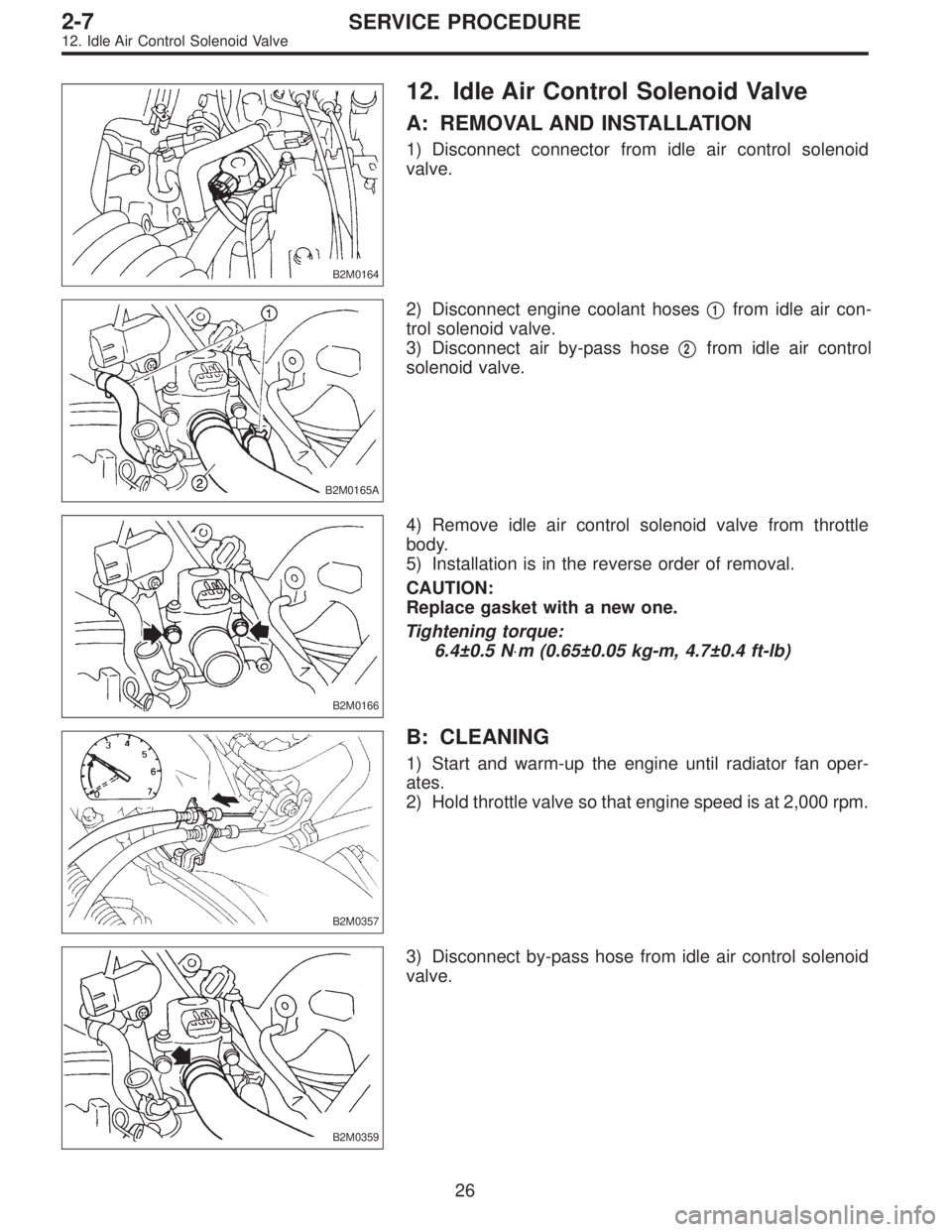
B2M0164
12. Idle Air Control Solenoid Valve
A: REMOVAL AND INSTALLATION
1) Disconnect connector from idle air control solenoid
valve.
B2M0165A
2) Disconnect engine coolant hoses�1from idle air con-
trol solenoid valve.
3) Disconnect air by-pass hose�
2from idle air control
solenoid valve.
B2M0166
4) Remove idle air control solenoid valve from throttle
body.
5) Installation is in the reverse order of removal.
CAUTION:
Replace gasket with a new one.
Tightening torque:
6.4±0.5 N⋅m (0.65±0.05 kg-m, 4.7±0.4 ft-lb)
B2M0357
B: CLEANING
1) Start and warm-up the engine until radiator fan oper-
ates.
2) Hold throttle valve so that engine speed is at 2,000 rpm.
B2M0359
3) Disconnect by-pass hose from idle air control solenoid
valve.
26
2-7SERVICE PROCEDURE
12. Idle Air Control Solenoid Valve
Page 720 of 2890
1. General Precaution
1) Remove or install engine and transmission in an area
where chain hoists, lifting devices, etc. are available for
ready use.
2) Be sure not to damage coated surfaces of body panels
with tools or stain seats and windows with coolant or oil.
Place a cover over fenders, as required, for protection.
3) Prior to starting work, prepare the following:
Service tools, clean cloth, containers to catch coolant and
oil, wire ropes, chain hoist, transmission jacks, etc.
4) Lift-up or lower the vehicle when necessary. Make sure
to support the correct positions. (Refer to Chapter 1-3
“General Information”.)
7
2-11SERVICE PROCEDURE
1. General Precaution
Page 721 of 2890

2. Engine
A: REMOVAL
1. Set the vehicle on lift arms.
2. Open front hood and support with a stay.
3. Release fuel pressure.
4. Disconnect battery cable and remove battery from vehicle.
5. Drain coolant.
6. Remove cooling system.
With A/C
7. Collect refrigerant, and remove pressure hoses.
8. Remove air intake system.
9. Remove canister and bracket.
10. Disconnect connectors, cables and hoses.
11. Remove power steering pump from bracket.
12. Remove front exhaust pipe and center exhaust pipe.
13. Remove nuts which hold lower side of transmission to
engine.
14. Remove nuts which install front cushion rubber onto front
crossmember.
AT model
15. Separate torque converter from drive plate.
16. Remove pitching stopper.
17. Disconnect fuel delivery hose, return hose and evaporation
hoses.
18. Support engine with a lifting device and wire ropes.
19. Support transmission with a garage jack.
20. Remove bolts which hold upper side of transmission to
engine.
21. Remove engine from vehicle.
�
�
�
�
�
�
�
�
�
�
�
�
�
�
�
8
2-11SERVICE PROCEDURE
2. Engine
Page 722 of 2890
1) Set the vehicle on lift arms.
2) Open front hood fully and support with stay.
G2M0341
3) Release fuel pressure.
(1) Disconnect fuel tank connector.
(2) Start the engine, and run until it stalls.
(3) After the engine stalls, crank it for five seconds
more.
(4) Turn ignition switch to“OFF”.
G6M0095
4) Disconnect battery cables and remove battery from
vehicle.
B2M0015A
5) Drain coolant.
Set container under the vehicle, and remove drain cock
from radiator.
G2M0263
6) Remove cooling system.
(1) Disconnect radiator fan motor connector.
(2) Disconnect radiator outlet hose from thermostat
cover.
9
2-11SERVICE PROCEDURE
2. Engine
Page 733 of 2890

B: INSTALLATION
1. Install engine to transmission.
2. Tighten bolts which hold upper side of transmission to engine.
3. Remove lifting device and wire rope.
4. Remove garage jack.
5. Install pitching stopper.
AT model
6. Install torque converter onto drive plate.
7. Install canister and bracket.
8. Install power steering pump on bracket.
9. Tighten nuts which hold lower side of transmission to engine.
10. Tighten nuts which install front cushion rubber onto cross-
member.
11. Install front exhaust pipe and center exhaust pipe.
12. Connect hoses, connectors and cables.
13. Install air intake system.
�Air intake duct
�Air cleaner element and upper cover.
With A/C
14. Install A/C pressure hoses.
15. Install cooling system.
16. Install battery onto the vehicle, and connect cables.
17. Fill coolant.
18. Check ATF level, and connect if necessary. [AT]
19. Correct power steering oil, and bleed air.
20. Remove front hood stay, and close front hood.
21. Take off the vehicle from lift arms.
�
�
�
�
�
�
�
�
�
�
�
�
20
2-11SERVICE PROCEDURE
2. Engine
Page 739 of 2890
G2M0267
(5) Connect radiator inlet hose.
B2M0016A
(6) Connect radiator outlet hose.
(7) Connect ATF cooler hoses. (AT model)
B2M0017
(8) Install V-belt cover.
16) Install battery in the vehicle, and connect cables.
17) Fill coolant.
18) Check ATF level and correct if necessary. (AT model)
19) Charge A/C system with refrigerant.
20) Remove front hood stay, and close front hood.
21) Take off the vehicle from lift arms.
26
2-11SERVICE PROCEDURE
2. Engine
Page 864 of 2890

3. Performance Test
A: STALL TEST
1. GENERAL
The stall test is of extreme importance in diagnosing the
condition of the automatic transmission and the engine. It
should be conducted to measure the engine stall speeds in
all shift ranges except the P and N ranges.
Purposes of the stall test:
1) To check the operation of the automatic transmission
clutch.
2) To check the operation of the torque converter clutch.
3) To check engine performance.
2. TEST METHODS
Preparations before test:
�
1Check that throttle valve opens fully.
�
2Check that engine oil level is correct.
�
3Check that coolant level is correct.
�
4Check that ATF level is correct.
�
5Check that differential gear oil level is correct.
�
6Increase ATF temperature to 50 to 80°C (122 to 176°F)
by idling the engine for approximately 30 minutes (with
select lever set to“N”or“P”).
1) Install an engine tachometer at a location visible from
the driver’s compartment and mark the stall speed range
on the tachometer scale.
2) Place the wheel chocks at the front and rear of all
wheels and engage the parking brake.
3) Move the manual linkage to ensure it operates properly,
and shift the select lever to the 2 range.
B3M0286B
4) While forcibly depressing the foot brake pedal, gradu-
ally depress the accelerator pedal until the engine operates
at full throttle.
5) When the engine speed is stabilized, read that speed
quickly and release the accelerator pedal.
6) Shift the select lever to Neutral, and cool down the
engine by idling it for more than one minute.
7) Record the stall speed.
8) If stall speed in 2 range is higher than specifications,
forward clutch slipping on brake band slipping may occur.
To identify it, conduct the same test as above in D range.
9) Perform the stall tests with the select lever in the R
range.
CAUTION:
�Do not continue the stall test for MORE THAN FIVE
SECONDS at a time (from closed throttle, fully open
throttle to stall speed reading). Failure to follow this
instruction causes the engine oil and ATF to deterio-
rate and the clutch and brake band to be adversely
affected.
38
3-2SERVICE PROCEDURE
3. Performance Test
 Install air cleaner element, air cleaner upper cover and
air intake duct.
19) Connect connector to mass air flow sensor.
B2M0154
5. Engine Coolant Temperature Sensor
A: REMOVAL AND INSTALL")
 Remove or install engine and transmission in an area
where chain hoists, lifting devices, etc. are available for
ready use.
2) Be sure not to damage coated surfaces of body pa")
 Set the vehicle on lift arms.
2) Open front hood fully and support with stay.
G2M0341
3) Release fuel pressure.
(1) Disconnect fuel tank connector.
(2) Start the engine, and run until it stalls.
(3")
 Connect radiator inlet hose.
B2M0016A
(6) Connect radiator outlet hose.
(7) Connect ATF cooler hoses. (AT model)
B2M0017
(8) Install V-belt cover.
16) Install battery in the vehicle, and c")