Page 1928 of 2890
10I1
CHECK DTC P0115 ON DISPLAY.
: Does the Subaru select monitor or OBD-II
general scan tool indicate DTC P0115?
: Inspect DTC P0115 using“10. Diagnostics Chart
with Trouble Code 2-7 [T1000]”.
NOTE:
In this case, it is not necessary to inspect DTC P0125.
: Replace engine coolant temperature sensor.
160
2-7ON-BOARD DIAGNOSTICS II SYSTEM
10. Diagnostics Chart with Trouble Code
Page 1930 of 2890
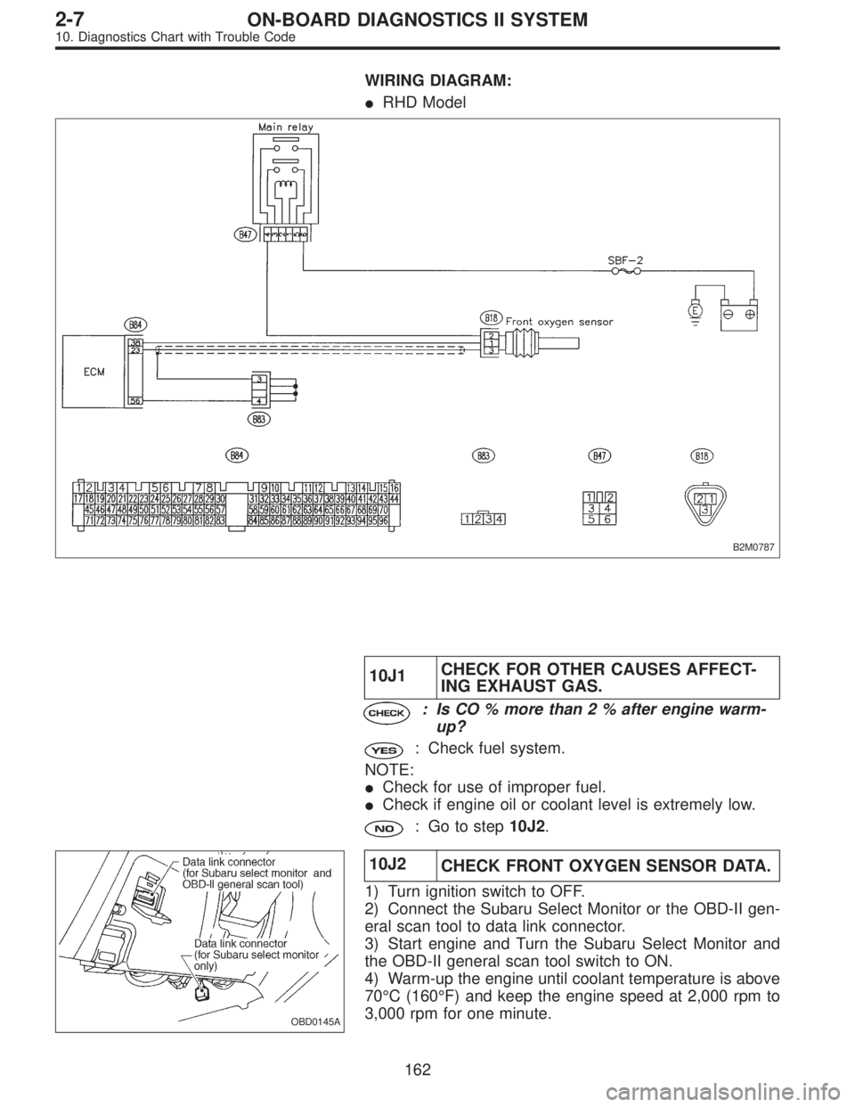
WIRING DIAGRAM:
�RHD Model
B2M0787
10J1CHECK FOR OTHER CAUSES AFFECT-
ING EXHAUST GAS.
: Is CO % more than 2 % after engine warm-
up?
: Check fuel system.
NOTE:
�Check for use of improper fuel.
�Check if engine oil or coolant level is extremely low.
: Go to step10J2.
OBD0145A
10J2
CHECK FRONT OXYGEN SENSOR DATA.
1) Turn ignition switch to OFF.
2) Connect the Subaru Select Monitor or the OBD-II gen-
eral scan tool to data link connector.
3) Start engine and Turn the Subaru Select Monitor and
the OBD-II general scan tool switch to ON.
4) Warm-up the engine until coolant temperature is above
70°C (160°F) and keep the engine speed at 2,000 rpm to
3,000 rpm for one minute.
162
2-7ON-BOARD DIAGNOSTICS II SYSTEM
10. Diagnostics Chart with Trouble Code
Page 1943 of 2890

10M1
CHECK DTC P0130 ON DISPLAY.
: Does the Subaru select monitor or OBD-II
general scan tool indicate DTC P0130?
: Go to step10M2.
: Go to step10M3.
10M2
CHECK FAILURE CAUSE OF P0130.
Perform the step 1 of DTC P0130.
: Is the failure cause of P0130 in the fuel sys-
tem?
: Check fuel system.
NOTE:
In this case, it is not necessary to inspect DTC P0136.
: Go to step10M3.
OBD0145A
10M3
CHECK REAR OXYGEN SENSOR DATA.
1) Turn ignition switch to OFF.
2) Connect Subaru Select Monitor or OBD-II general scan
tool to data link connector.
3) Start the engine, and turn Subaru Select Monitor or
OBD-II general scan tool switch to ON.
4) Warm-up the engine until engine coolant temperature is
above 70°C (160°F), and keep the engine speed at 2,000
rpm to 3,000 rpm for two minutes.
B2M0488
5) Read data on Subaru Select Monitor or OBD-II general
scan tool.
�Subaru Select Monitor
Designate mode using function key.
Function mode: F13
�F13: Rear oxygen sensor output signal is indicated.
: Does the value fluctuate in function mode
F13?
: Go to step10M5.
: Go to next.
175
2-7ON-BOARD DIAGNOSTICS II SYSTEM
10. Diagnostics Chart with Trouble Code
Page 1953 of 2890
OBD0240
P: DTC P0170
—FUEL TRIM MALFUNCTION (FUEL)—
DTC DETECTING CONDITION:
�Two consecutive trips with fault
TROUBLE SYMPTOM:
�Erroneous idling
�Engine stalls.
�Poor driving performance
10P1Check exhaust system.
10P2Check air intake system.
10P3Check fuel pressure.
10P4Check engine coolant temperature sensor.
10P5Check mass air flow sensor.
CAUTION:
After repair or replacement of faulty parts, conduct
CLEAR MEMORY and INSPECTION MODE.
�
�
�
�
185
2-7ON-BOARD DIAGNOSTICS II SYSTEM
10. Diagnostics Chart with Trouble Code
Page 1956 of 2890
OBD0145A
10P4CHECK ENGINE COOLANT TEMPERA-
TURE SENSOR.
1) Turn ignition switch to OFF.
2) Connect the Subaru Select Monitor or the OBD-II gen-
eral scan tool to data link connector.
3) Start the engine and warm-up completely.
B2M0479
4) Read data on Subaru Select Monitor or the OBD-II gen-
eral scan tool.
�Subaru Select Monitor
Designate mode using function key.
Function mode: F04
�F04: Water temperature is indicated in“°C”and“°F”.
: Is temperature greater than 60°Cor140°Fin
function mode F04?
: Go to step10P5.
: Replace engine coolant temperature sensor.
�OBD-II general scan tool
For detailed operation procedures, refer to the OBD-II Gen-
eral Scan Tool Instruction Manual.
188
2-7ON-BOARD DIAGNOSTICS II SYSTEM
10. Diagnostics Chart with Trouble Code
Page 1957 of 2890
 Turn ignition switch to OFF.
2) Connect the Subaru Select Monitor or the OBD-II gen-
eral scan tool to data link connector.
3) Start the engine and warm-up")
OBD0145A
10P5
CHECK MASS AIR FLOW SENSOR.
1) Turn ignition switch to OFF.
2) Connect the Subaru Select Monitor or the OBD-II gen-
eral scan tool to data link connector.
3) Start the engine and warm-up engine until coolant tem-
perature is greater than 60°C (140°F).
4) Place the selector lever in“N”or“P”position.
5) Turn A/C switch to OFF.
6) Turn all accessory switches to OFF.
B2M0481
7) Read data on Subaru Select Monitor or OBD-II general
scan tool.
�Subaru Select Monitor
Designate mode using function key.
Function mode: F06
�F06: Mass air flow and voltage input from mass air flow
sensor are shown on display.
: Is the voltage in function mode F06 within
the specifications shown in the following
table?
Model Engine speed Specified value
2200 ccIdling 1.7—3.3 (g/sec)
2,500 rpm 7.1—14.2 (g/sec)
2500 ccIdling 2.2—4.2 (g/sec)
2,500 rpm 8.6—14.5 (g/sec)
: Contact with SOA service.
NOTE:
Inspection by DTM is required, because probable cause is
deterioration of multiple parts.
: Replace mass air flow sensor.
�OBD-II general scan tool
For detailed operation procedures, refer to the OBD-II Gen-
eral Scan Tool Instruction Manual.
189
2-7ON-BOARD DIAGNOSTICS II SYSTEM
10. Diagnostics Chart with Trouble Code
Page 2837 of 2890
![SUBARU LEGACY 1996 Service Repair Manual 7. Electrical Unit Location
Electrical unit Refer to;
A.B.S. control module 4-4a [T300]
A.B.S. G sensor (MT) 4-4a [T300]
A/C compressor relay�
7
A/C fuse�11
A/C main fan relay 1�10
A/C main fan relay](/manual-img/17/57433/w960_57433-2836.png "SUBARU LEGACY 1996 Service Repair Manual 7. Electrical Unit Location
Electrical unit Refer to;
A.B.S. control module 4-4a [T300]
A.B.S. G sensor (MT) 4-4a [T300]
A/C compressor relay�
7
A/C fuse�11
A/C main fan relay 1�10
A/C main fan relay")
7. Electrical Unit Location
Electrical unit Refer to;
A.B.S. control module 4-4a [T300]
A.B.S. G sensor (MT) 4-4a [T300]
A/C compressor relay�
7
A/C fuse�11
A/C main fan relay 1�10
A/C main fan relay 2�8
A/C pressure switch�2
A/C sub fan relay 2�9
ATF temperature sensor 2-7 [T2B1]
Blower motor resistor�
26
Blower relay�13
Camshaft position sensor 2-7 [T2A2]
Check connector�
25
Clutch switch (MT) 6-2 [T300]
Crankshaft position sensor 2-7 [T2A2]
Cruise control module 6-2 [T300]
Cruise control pump 6-2 [T300]
Data link connector (for OBD-II G.S.T.) 2-7 [T2A1]
Data link connector (for S.S.M.) 2-7 [T2A1]
Diagnosis connector 4-4a [T300]
Diagnosis terminal (Ground) 4-4a [T300]
Door lock timer�
27
Engine control module 2-7 [T2A1]
Engine coolant temperature sensor 2-7 [T2A2]
Engine hood switch (Security) 6-2 [K6A0]
Evaporator thermoswitch�
29
F/B�15
FRESH/RECIRC actuator�28
Fuel pump relay 2-7 [T2A3]
Fuel gauge module�
31
Fuel gauge sub module (AWD)�32
FWD switch (AT)�1
Headlight alarm relay (Security) 6-2 [K6A0]
Headlight relay LH�
5
Headlight relay RH�6
Horn relay�14
Electrical unit Refer to;
Hydraulic unit (A.B.S.) 4-4a [T300]
Ignition coil 2-7 [T2A3]
Ignitor 2-7 [T2A3]
Idle air control solenoid valve 2-7 [T2A3]
Illumination control module�
21
Inhibitor switch 6-2 [T300]
Knock sensor 2-7 [T2A2]
Main fan relay�
19
Main relay 2-7 [T2A3]
Mass air flow sensor 2-7 [T2A2]
Mode actuator�
12
M/B�4
Oil pressure switch�3
Oxygen sensor 2-7 [T2A2]
Pedal stroke sensor (T.C.S.) 4-4b [T300]
Power window and sunroof relay�
24
Power window circuit breaker�23
Purge control solenoid valve 2-7 [T2A3]
Rear defogger relay�
17
Seat belt timer�20
Security control module 6-2 [K6A0]
Shift lock control module�
22
Starter interrupt relay (Security) 6-2 [K6A0]
Stop & brake switch (With cruise con-
trol)6-2 [T300]
Sunroof control module�
30
Tail and illumination relay�18
T.C.S. control module 4-4b [T300]
T.C.S. motor relay 4-4b [T300]
T.C.S. valve relay 4-4b [T300]
Throttle position sensor 2-7 [T2A2]
Test mode connector 2-7 [T2A1]
Transmission control module 2-7 [T2B1]
Turn & hazard module�
16
Vehicle speed sensor 1 2-7 [T2B1]
Vehicle speed sensor 2 2-7 [T2B1]
107
6-3WIRING DIAGRAM
7. Electrical Unit Location
Page 2853 of 2890

Connector Connecting to
No. Pole Color Area No. Name
E1 6 * A-3 B20
Bulkhead wiring harness E2 12 Gray A-3 B21
E3 16 Gray A-3 B22
E4 2 Blue A-2 Purge control solenoid valve
E5 2 Light gray A-2 Injector #1
E6 2 Dark gray A-3 Injector #3
E7 3 Gray A-3 Idle air control solenoid valve
E8 2 Brown B-3 Engine coolant temperature sensor
E9 1 * B-3 Thermometer
E10 2 Gray B-3 Crankshaft position sensor
E11 1 * B-3 Oil pressure switch
E12 3 Gray A-3 Ignition coil
E13 3 Brown A-3 Throttle position sensor
E14 1 Gray B-3 Knock sensor
E15 2 Dark gray B-4 Camshaft position sensor
E16 2 Light gray B-4 Injector #2
E17 2 Dark gray B-4 Injector #4
E18 2 Brown B-3 EGR solenoid (AT)
*: Non-colored
Connector Connecting to
No. Pole Color Area No. Name
T1 2 Gray C-1 B24
Bulkhead wiring harness (MT)
T2 2 Brown C-1 B25
T3 12 Gray D-3 B12
Bulkhead wiring harness (AT)
T4 16 Gray D-3 B11
T5 4 Gray C-1/C-3 B19 Bulkhead wiring harness
T6 4 Gray D-2/D-4 Rear oxygen sensor
123
6-3WIRING DIAGRAM
8. Electrical Wiring Harness and Ground Point
![SUBARU LEGACY 1996 Service Repair Manual 10I1
CHECK DTC P0115 ON DISPLAY.
: Does the Subaru select monitor or OBD-II
general scan tool indicate DTC P0115?
: Inspect DTC P0115 using“10. Diagnostics Chart
with Trouble Code 2-7 [T1000]”.
NO](/manual-img/17/57433/w960_57433-1927.png "SUBARU LEGACY 1996 Service Repair Manual 10I1
CHECK DTC P0115 ON DISPLAY.
: Does the Subaru select monitor or OBD-II
general scan tool indicate DTC P0115?
: Inspect DTC P0115 using“10. Diagnostics Chart
with Trouble Code 2-7 [T1000]”.
NO")
![SUBARU LEGACY 1996 Service Repair Manual OBD0145A
10P4CHECK ENGINE COOLANT TEMPERA-
TURE SENSOR.
<REF. TO 2-7 F: DTC P0115 [T10F0].>
1) Turn ignition switch to OFF.
2) Connect the Subaru Select Monitor or the OBD-II gen-
eral scan tool to da](/manual-img/17/57433/w960_57433-1955.png "SUBARU LEGACY 1996 Service Repair Manual OBD0145A
10P4CHECK ENGINE COOLANT TEMPERA-
TURE SENSOR.
<REF. TO 2-7 F: DTC P0115 [T10F0].>
1) Turn ignition switch to OFF.
2) Connect the Subaru Select Monitor or the OBD-II gen-
eral scan tool to da")