Page 1777 of 2890

�
2Ignition coil
�
3Ignitor
�
4Crankshaft position sensor
�
5Camshaft position sensor
�
6Throttle position sensor
�
7Fuel injectors
�
8Pressure regulator
�
9Engine coolan")
�1Engine control module (ECM)
�
2Ignition coil
�
3Ignitor
�
4Crankshaft position sensor
�
5Camshaft position sensor
�
6Throttle position sensor
�
7Fuel injectors
�
8Pressure regulator
�
9Engine coolant temperature sensor
�
10Mass air flow sensor
�
11Idle air control solenoid valve
�
12Purge control solenoid valve
�
13Fuel pump
�
14PCV valve
�
15Air cleaner
�
16Canister
�
17Main relay
�
18Fuel pump relay
�
19Fuel filter
�
20Front catalytic converter
�
21Rear catalytic converter
�
22EGR valve�
23EGR control solenoid valve
�
24Radiator fan
�
25Radiator fan relay
�
26Pressure sources switching solenoid valve
�
27Knock sensor
�
28Back-pressure transducer
�
29Front oxygen sensor
�
30Rear oxygen sensor
�
31Pressure sensor
�
32A/C compressor
�
33Inhibitor switch
�
34CHECK ENGINE malfunction indicator lamp (MIL)
�
35Tachometer
�
36A/C relay
�
37A/C control module
�
38Ignition switch
�
39Transmission control module (TCM)
�
40Vehicle speed sensor
�
41Data link connector (Subaru select monitor)
�
42Data link connector (OBD-II general scan tool)
�
43Two way valve
�
44Filter
9
2-7ON-BOARD DIAGNOSTICS II SYSTEM
1. General
Page 1779 of 2890

�
2Ignition coil
�
3Ignitor
�
4Crankshaft position sensor
�
5Camshaft position sensor
�
6Throttle position sensor
�
7Fuel injectors
�
8Pressure regulator
�
9Engine coolan")
�1Engine control module (ECM)
�
2Ignition coil
�
3Ignitor
�
4Crankshaft position sensor
�
5Camshaft position sensor
�
6Throttle position sensor
�
7Fuel injectors
�
8Pressure regulator
�
9Engine coolant temperature sensor
�
10Mass air flow sensor
�
11Idle air control solenoid valve
�
12Purge control solenoid valve
�
13Fuel pump
�
14PCV valve
�
15Air cleaner
�
16Canister
�
17Main relay
�
18Fuel pump relay
�
19Fuel filter
�
20Front catalytic converter
�
21Rear catalytic converter
�
22EGR valve
�
23EGR control solenoid valve�
24Radiator fan
�
25Radiator fan relay
�
26Pressure sources switching solenoid valve
�
27Knock sensor
�
28Back-pressure transducer
�
29Front oxygen sensor
�
30Rear oxygen sensor (Except California model)
�
31Pressure sensor
�
32A/C compressor
�
33Inhibitor switch
�
34CHECK ENGINE malfunction indicator lamp (MIL)
�
35Tachometer
�
36A/C relay
�
37A/C control module
�
38Ignition switch
�
39Transmission control module (TCM)
�
40Vehicle speed sensor 2
�
41Data link connector (For Subaru select monitor)
�
42Data link connector (For Subaru select monitor and OBD-II
general scan tool)
�
43Two way valve
�
44Rear oxygen sensor (California model only)
�
45Filter
11
2-7ON-BOARD DIAGNOSTICS II SYSTEM
1. General
Page 1783 of 2890
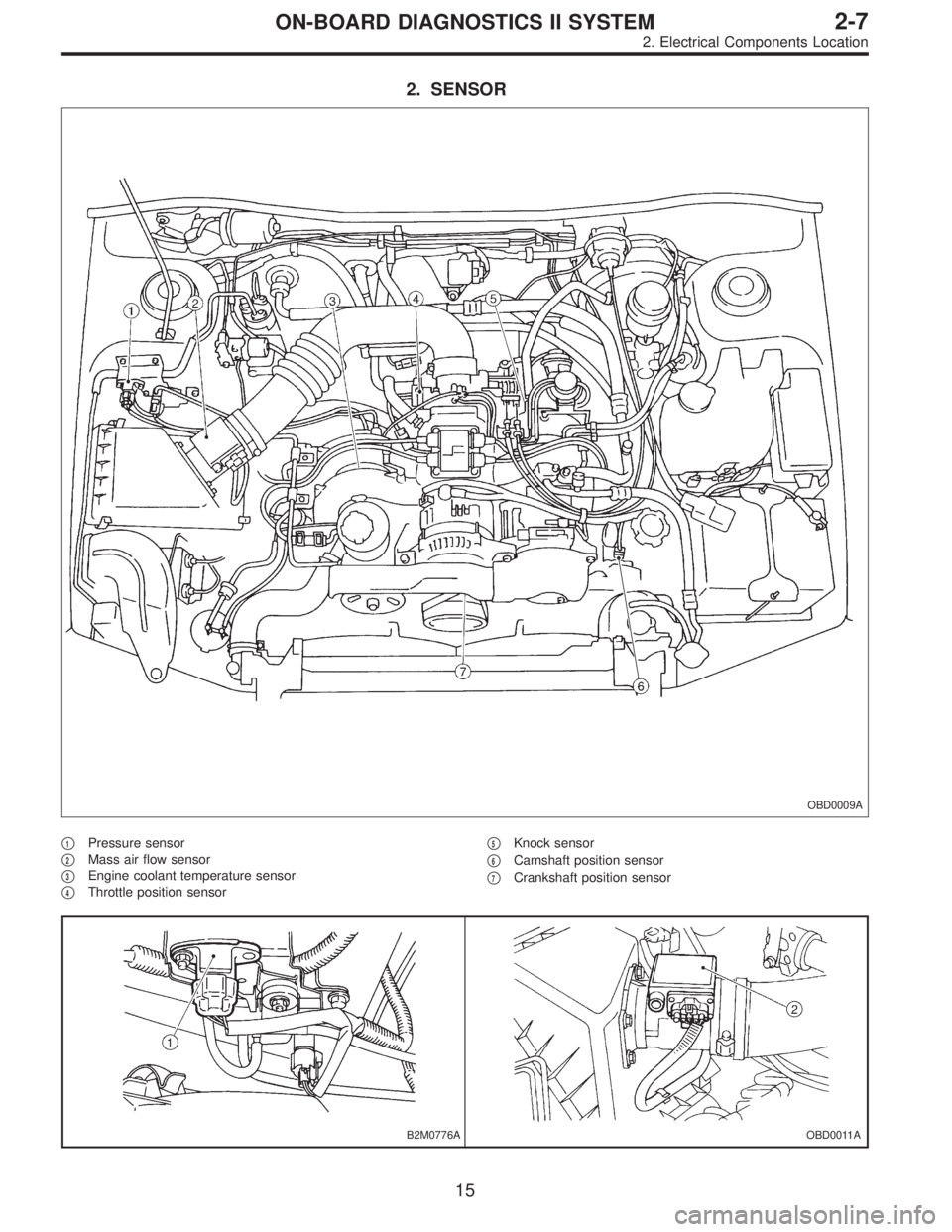
2. SENSOR
OBD0009A
�1Pressure sensor
�
2Mass air flow sensor
�
3Engine coolant temperature sensor
�
4Throttle position sensor�
5Knock sensor
�
6Camshaft position sensor
�
7Crankshaft position sensor
B2M0776AOBD0011A
15
2-7ON-BOARD DIAGNOSTICS II SYSTEM
2. Electrical Components Location
Page 1798 of 2890

Refers to data denoting the current operating condition of
analog input/output, digital input/output and/or the power-
train system.
A list of the supp")
3. CURRENT POWERTRAIN DIAGNOSTIC DATA
(MODE $01)
Refers to data denoting the current operating condition of
analog input/output, digital input/output and/or the power-
train system.
A list of the support data and PID (Parameter Identification)
codes are shown in the following table.
PID DataUnit of measure
01 Number of emission-related powertrain trouble codes and MIL status ON/OFF
03 Fuel system control status—
04 Calculated engine load value%
05 Engine coolant temperature°C
06 Short term fuel trim%
07 Long term fuel trim%
0B Intake manifold absolute pressurekPa
0C Engine revolutionrpm
0D Vehicle speedkm/h
0E Ignition timing advance°
10 Air flow rate from mass air flow sensor g/sec
11 Throttle valve opening angle%
13 Check whether oxygen sensor is installed.—
14 Oxygen sensor output voltage and short term fuel trim associated with oxygen sensor—bank 1 V and %
15 Oxygen sensor output voltage and short term fuel trim associated with oxygen sensor—bank 2 V and %
1C On-board diagnosis system—
NOTE:
Refer to OBD-II general scan tool manufacturer’s instruc-
tion manual to access generic OBD-II PIDs (MODE $01).
4. POWERTRAIN FREEZE FRAME DATA (MODE $02)
Refers to data denoting the operating condition when
trouble is sensed by the on-board diagnosis system.
A list of the support data and PID (Parameter Identification)
codes are shown in the following table.
PID DataUnit of measure
02 Trouble code that caused CARB required freeze frame data storage—
03 Fuel system control status—
04 Calculated engine load value%
05 Engine coolant temperature°C
06 Short term fuel trim%
07 Long term fuel trim%
0B Intake manifold absolute pressurekPa
0C Engine revolutionrpm
0D Vehicle speedkm/h
NOTE:
Refer to OBD-II general scan tool manufacturer’s instruc-
tion manual to access freeze frame data (MODE $02).
30
2-7ON-BOARD DIAGNOSTICS II SYSTEM
3. Diagnosis System
Page 1805 of 2890

6. READ DATA FUNCTION KEY LIST FOR ENGINE
Function mode Contents Abbreviation Unit of measure
F00 ROM ID number YEAR—
F01 Battery voltage VB V
F02 Vehicle speed signal VSP km/h, MPH
F03 Engine speed signal EREV rpm
F04 Engine coolant temperature signal TW°C,°F
F05 Ignition signal ADVS deg
F06 Mass air flow signal QA g/s, V
F07 Throttle position signal THV %, V
F08 Injector pulse width TIM mS
F09 Idle air control signal ISC %
F10 Load data LOAD %
F11 Front oxygen sensor output signal O2 V
F12 Front oxygen sensor maximum and minimum output signal O2max - min V, V
F13 Rear oxygen sensor output signal RO2 V
F14 Rear oxygen sensor maximum and minimum output signal RO2max - min V, V
F17 Short term fuel trim ALPHA %
F19 Knock sensor signal KNOCK deg
F20 Atmospheric absolute pressure signal BARO. P kPa, mmHg
F21 Intake manifold absolute pressure signal MANI. P kPa, mmHg
F29 A/F correction (short term trim) by rear oxygen sensor PHOS %
F30 Long term fuel trim KBLRC %
F31 Long term whole fuel trim K0 %
F32 Front oxygen sensor heater current FO2H A
F33 Rear oxygen sensor heater current RO2H A
F35 Purge control solenoid valve duty ratio CPCD %
F36Maximum value of cylinder #1 misfire times during 100 rota-
tionsMF1 %
F37Maximum value of cylinder #2 misfire times during 100 rota-
tionsMF2 %
F38Maximum value of cylinder #3 misfire times during 100 rota-
tionsMF3 %
F39Maximum value of cylinder #4 misfire times during 100 rota-
tionsMF4 %
F42Maximum and minimum EGR system pressure value (AT
vehicles only)EGRmax - min kPa
F43 Fuel tank pressure signal TNKP kPa, mmHg
F44 Fuel temperature signal TNKT°C,°F
F45 Fuel level signal FLEVEL V
FA 0 O N)OFF signal——
FA 1 O N)OFF signal——
FA 2 O N)OFF signal——
FA 3 O N)OFF signal——
FA 4 O N)OFF signal——
FA 5 O N)OFF signal——
FB0 Diagnostic trouble code (DTC) INSPECT—
FB1 Diagnostic trouble code (DTC) OBD—
37
2-7ON-BOARD DIAGNOSTICS II SYSTEM
3. Diagnosis System
Page 1806 of 2890
 LOAD�F %
Engine coolant temperature signal (Freeze frame data) TW�F °C
Throttle position signal (Freeze frame data")
Function mode Contents Abbreviation Unit of measure
FB2Load data (Freeze frame data) LOAD�F %
Engine coolant temperature signal (Freeze frame data) TW�F °C
Throttle position signal (Freeze frame data) ALPH�F %
Long term fuel trim (Freeze frame data) KBLR�F %
Intake manifold absolute pressure signal (Freeze frame data) MANI�F kPa
Engine speed signal (Freeze frame data) EREV�F rpm
Vehicle speed signal (Freeze frame data) VSP�F km/h
FB3Mass air flow signal (Freeze frame data) QA�F (P0100) V
Pressure signal (Freeze frame data) PS�F (P0105) V
Pressure signal (Freeze frame data) PR�F (P0106) V
Engine coolant temperature signal (Freeze frame data) TW�F (P0115) V
Throttle position signal (Freeze frame data) THV�F (P0120) V
EGR control solenoid valve signal (Freeze frame data) EGR (P0403) —*1
Purge control solenoid valve signal (Freeze frame data) CPC (P0443) —*1
Start switch signal (Freeze frame data) STSW (P1100) —*1
Pressure sources switching solenoid valve signal (Freeze
frame data)BR1 (P1102) —*1
Radiator fan relay 1 signal (Freeze frame data) FAN1 (P1500) —*1
FC0 Clear memory — —
FD01 Compulsory fuel pump relay operation check FUEL PUMP —
FD02 Compulsory purge control solenoid valve operation check CPC SOL —
FD03 Compulsory radiator fan relay operation check RAD FAN —
FD04 Compulsory A/C relay operation check A/C RELAY —
FD05 Compulsory EGR control solenoid valve operation check EGR SOL —
FD07 Compulsory pressure control solenoid valve operation check PCV SOL —
FD08 Compulsory vent control solenoid valve operation check VENT SOL —
FD10Compulsory pressure sources switching solenoid valve opera-
tion checkBR SOL —
NOTE:
1) Subaru select monitor is also available for monitoring
information other than that used for check and repair of the
vehicle.
2) F42 (Maximum and minimum EGR system pressure
value) will not read accurately until the EGR flow diagno-
sis terminates.
EGR flow diagnosis terminates when LED No. 2 illuminates
at function mode FA4.
3) *1: “Hi” or “Low” is shown instead of measured value.
4) Because ASV solenoid valve, FICD solenoid valve and
air injection system diagnosis solenoid valve are not
installed, FD06, FD09 and FD11 will be displayed but non-
functional.
38
2-7ON-BOARD DIAGNOSTICS II SYSTEM
3. Diagnosis System
Page 1808 of 2890
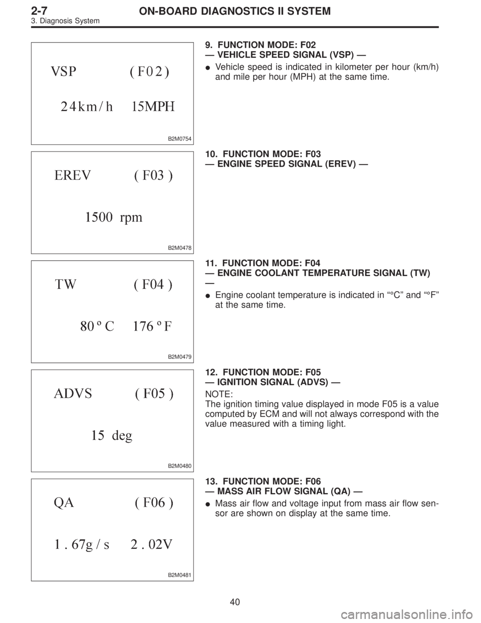
B2M0754
9. FUNCTION MODE: F02
—VEHICLE SPEED SIGNAL (VSP)—
�Vehicle speed is indicated in kilometer per hour (km/h)
and mile per hour (MPH) at the same time.
B2M0478
10. FUNCTION MODE: F03
—ENGINE SPEED SIGNAL (EREV)—
B2M0479
11. FUNCTION MODE: F04
—ENGINE COOLANT TEMPERATURE SIGNAL (TW)
—
�Engine coolant temperature is indicated in“°C”and“°F”
at the same time.
B2M0480
12. FUNCTION MODE: F05
—IGNITION SIGNAL (ADVS)—
NOTE:
The ignition timing value displayed in mode F05 is a value
computed by ECM and will not always correspond with the
value measured with a timing light.
B2M0481
13. FUNCTION MODE: F06
—MASS AIR FLOW SIGNAL (QA)—
�Mass air flow and voltage input from mass air flow sen-
sor are shown on display at the same time.
40
2-7ON-BOARD DIAGNOSTICS II SYSTEM
3. Diagnosis System
Page 1818 of 2890
Current trouble code indicated by on-board
diagnostics after clear memo")
47. FB MODE FOR ENGINE
Function mode Abbreviation Contents Contents of display Page
FB0 INSPECT On-board diagnostics (Inspection)Current trouble code indicated by on-board
diagnostics after clear memory.58
FB1 OBD On-board diagnostics (Read data)Current trouble code indicated by on-board
diagnostics.32
FB2LOAD�F Load data
�Freeze frame data
�Data stored at the time of trouble
occurrence, is shown on display.34
TW�F Engine coolant temperature signal
ALPH�F Throttle position signal
KBLR�F Long term fuel trim
MANI�FIntake manifold absolute pressure
signal
EREV�F Engine speed signal
VSP�F Vehicle speed signal
FB3QA�F (P0100) Mass air flow signal
�Freeze frame data
�Data stored at the time of trouble
occurrence, is shown on display.35
PS�F (P0105) Pressure signal
PR�F (P0106) Pressure signal
TW�F (P0115) Engine coolant temperature signal
THV�F (P0120) Throttle position signal
EGR (P0403) EGR control solenoid valve signal
CPC (P0443) Purge control solenoid valve signal
STSW (P1100) Start switch signal
BR1 (P1102)Pressure sources switching sole-
noid valve signal
FAN1 (P1500) Radiator fan relay 1 signal
48. FC MODE FOR ENGINE
Function mode Abbreviation Contents Contents of display Page
FC0 MEMORY CLR Back-up memory clearFunction of clearing trouble code stored in
memory.57
49. FD MODE FOR ENGINE
Function mode Abbreviation Contents Contents of display Page
FD01 FUEL PUMP
Compulsory valve operation checkFunction of checking operation of fuel
pump relay, purge control solenoid valve,
radiator fan relay, A/C relay, EGR control
solenoid valve, pressure control solenoid
valve, vent control solenoid valve and pres-
sure sources switching solenoid valve.63
FD02 CPC SOL
FD03 RAD FAN
FD04 A/C RELAY
FD05 EGR SOL
FD07 PCV SOL
FD08 VENT SOL
FD10 BR SOL
NOTE:
Because ASV solenoid valve, FICD solenoid valve and air
injection system diagnosis solenoid valve are not installed,
FD06, FD09 and FD11 will be displayed but non-functional.
50
2-7ON-BOARD DIAGNOSTICS II SYSTEM
3. Diagnosis System