Page 622 of 2890

�
2Intake manifold gasket RH
(2200 cc model)
�
3Intake manifold gasket LH
(2500 cc model)
�
4Intake manifold gasket RH
(2500 cc")
1. Intake Manifold
B2M0739A
�1Intake manifold gasket LH
(2200 cc model)
�
2Intake manifold gasket RH
(2200 cc model)
�
3Intake manifold gasket LH
(2500 cc model)
�
4Intake manifold gasket RH
(2500 cc model)
�
5Fuel injector pipe insulator
�
6Fuel injector pipe
�
7O-ring A
�
8O-ring B
�
9Fuel injector
�
10Insulator
�
11Fuel injector cap
�
12Plate
�
13Sealing�
14Gasket
�
15Engine coolant hose B
�
16Air by-pass hose
�
17Idle air control solenoid valve
�
18Engine coolant hose A
�
19Nipple (AT model)
�
20Plug
�
21PCV valve
�
22Purge control solenoid valve
�
23Nipple
�
24BPT
�
25BPT holder bracket
�
26Back pressure hose
�
27EGR vacuum hose A
�
28EGR vacuum pipe
�
29EGR vacuum hose C
�
30EGR valve�
31Gasket
�
32EGR vacuum hose B
�
33EGR solenoid valve
�
34EGR pipe
�
35Collar
�
36Intake manifold
Tightening torque: N⋅m (kg-m, ft-lb)
T1: 3.4±0.5 (0.35±0.05, 2.5±0.4)
T2: 6.4±0.5 (0.65±0.05, 4.7±0.4)
T3: 16±1.5 (1.6±0.15, 11.6±1.1)
T4: 19±1 (1.9±0.1, 13.7±0.7)
T5: 19±1.5 (1.9±0.15, 13.7±1.1)
T6: 23±3 (2.3±0.3, 16.6±2.2)
T7: 25±2 (2.5±0.2, 18.1±1.4)
T8: 34±2 (3.5±0.2, 25.3±1.4)
2
2-7COMPONENT PARTS
1. Intake Manifold
Page 627 of 2890
B2M0154
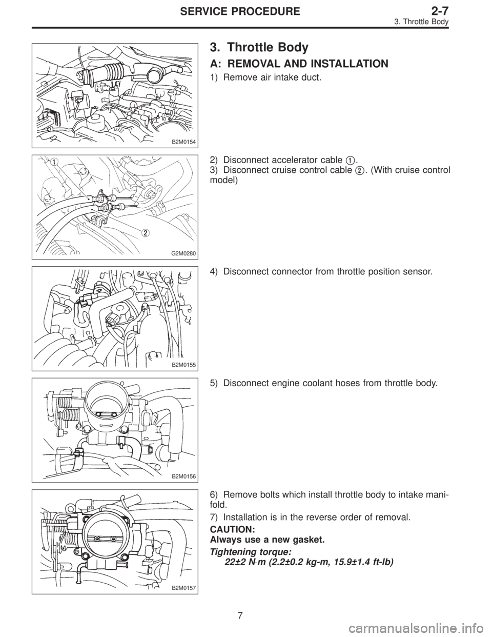
3. Throttle Body
A: REMOVAL AND INSTALLATION
1) Remove air intake duct.
G2M0280
2) Disconnect accelerator cable�1.
3) Disconnect cruise control cable�
2. (With cruise control
model)
B2M0155
4) Disconnect connector from throttle position sensor.
B2M0156
5) Disconnect engine coolant hoses from throttle body.
B2M0157
6) Remove bolts which install throttle body to intake mani-
fold.
7) Installation is in the reverse order of removal.
CAUTION:
Always use a new gasket.
Tightening torque:
22±2 N⋅m (2.2±0.2 kg-m, 15.9±1.4 ft-lb)
7
2-7SERVICE PROCEDURE
3. Throttle Body
Page 629 of 2890
B2M0334
(3) Remove bolts which install power steering pump
from bracket.
B2M0029
(4) Place power steering pump on the right side wheel
apron.
B6M0160
8) Disconnect spark plug cords from ignition coil.
H2M1246
9) Disconnect engine coolant hoses from throttle body.
H2M1259A
10) Disconnect engine coolant hose�1from idle air con-
trol solenoid valve.
11) Disconnect air by-pass hose�
2from idle air control
solenoid valve.
9
2-7SERVICE PROCEDURE
4. Intake Manifold
Page 630 of 2890
B2M0342
12) Disconnect brake booster hose.
B2M0343
13) Remove EGR pipe.
G2M0370
14) Disconnect canister hose from pipe.
B2M0019
15) Disconnect engine harness connectors from bulkhead
harness connectors.
B2M0345A
16) Disconnect connectors from engine coolant tempera-
ture sensor�
1and thermometer�2.
10
2-7SERVICE PROCEDURE
4. Intake Manifold
Page 635 of 2890
G2M0408
4) Connect connector to crankshaft position sensor.
G2M0416
5) Connect connector to camshaft position sensor.
B2M0346
6) Connect connector to knock sensor.
B2M0345A
7) Connect connectors to engine coolant temperature sen-
sor�
1and thermometer�2.
B2M0019
8) Connect engine harness connector to bulkhead har-
ness connectors.
15
2-7SERVICE PROCEDURE
4. Intake Manifold
Page 636 of 2890
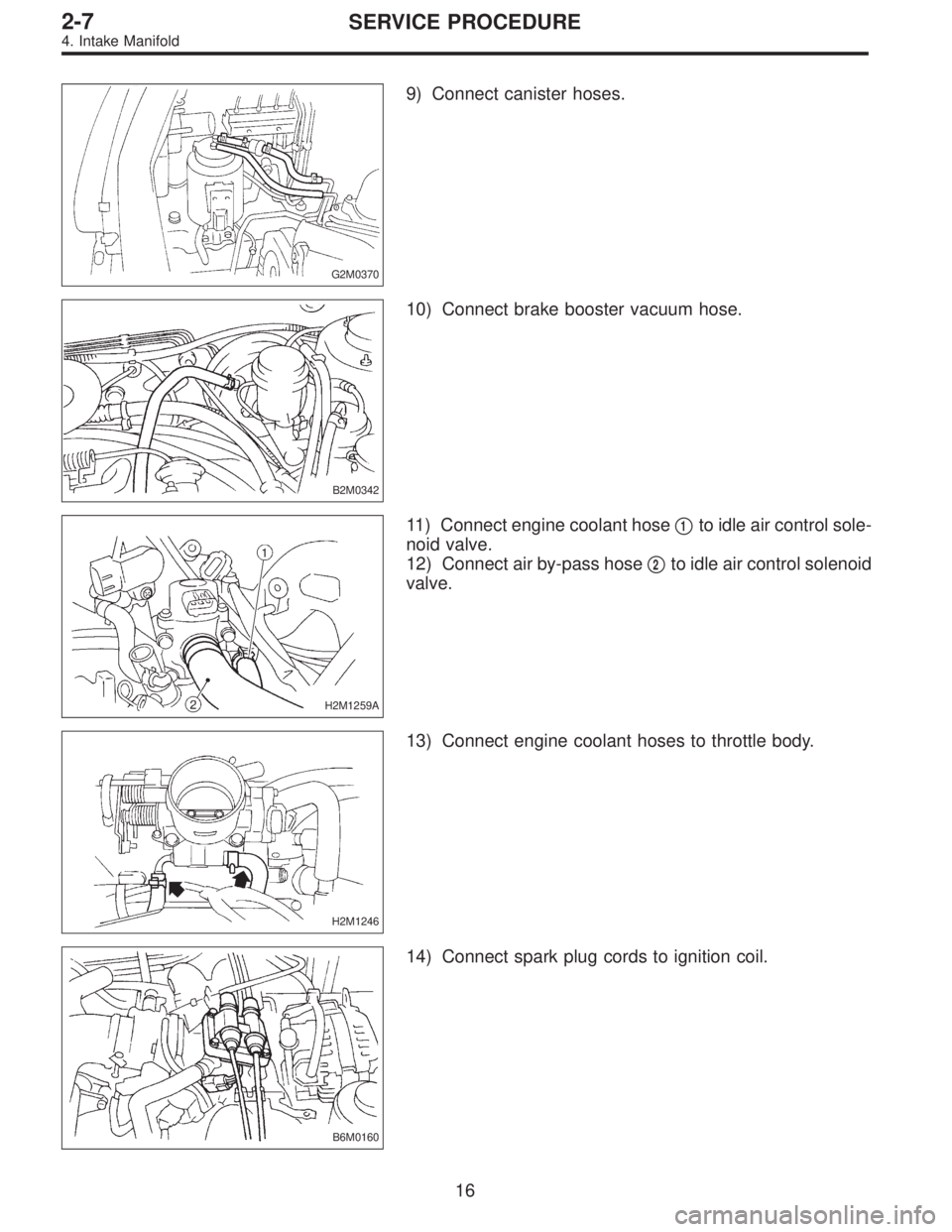
G2M0370
9) Connect canister hoses.
B2M0342
10) Connect brake booster vacuum hose.
H2M1259A
11) Connect engine coolant hose�1to idle air control sole-
noid valve.
12) Connect air by-pass hose�
2to idle air control solenoid
valve.
H2M1246
13) Connect engine coolant hoses to throttle body.
B6M0160
14) Connect spark plug cords to ignition coil.
16
2-7SERVICE PROCEDURE
4. Intake Manifold
Page 638 of 2890
B2M0154
18) Install air cleaner element, air cleaner upper cover and
air intake duct.
19) Connect connector to mass air flow sensor.
B2M0154
5. Engine Coolant Temperature Sensor
A: REMOVAL AND INSTALLATION
1) Remove air intake duct.
G2M0407
2) Disconnect connector from engine coolant temperature
sensor.
3) Remove engine coolant temperature sensor.
G2M0407
4) Installation is in the reverse order of removal.
Tightening torque:
25±3 N⋅m (2.5±0.3 kg-m, 18.1±2.2 ft-lb)
G2M0408
6. Crankshaft Position Sensor
A: REMOVAL AND INSTALLATION
1) Remove bolt which install crankshaft position sensor to
cylinder block.
18
2-7SERVICE PROCEDURE
4. Intake Manifold - 6. Crankshaft Position Sensor
Page 639 of 2890
B2M0154
18) Install air cleaner element, air cleaner upper cover and
air intake duct.
19) Connect connector to mass air flow sensor.
B2M0154
5. Engine Coolant Temperature Sensor
A: REMOVAL AND INSTALLATION
1) Remove air intake duct.
G2M0407
2) Disconnect connector from engine coolant temperature
sensor.
3) Remove engine coolant temperature sensor.
G2M0407
4) Installation is in the reverse order of removal.
Tightening torque:
25±3 N⋅m (2.5±0.3 kg-m, 18.1±2.2 ft-lb)
G2M0408
6. Crankshaft Position Sensor
A: REMOVAL AND INSTALLATION
1) Remove bolt which install crankshaft position sensor to
cylinder block.
18
2-7SERVICE PROCEDURE
4. Intake Manifold - 6. Crankshaft Position Sensor
 Remove bolts which install power steering pump
from bracket.
B2M0029
(4) Place power steering pump on the right side wheel
apron.
B6M0160
8) Disconnect spark plug cords from ignition coil.")
 Disconnect brake booster hose.
B2M0343
13) Remove EGR pipe.
G2M0370
14) Disconnect canister hose from pipe.
B2M0019
15) Disconnect engine harness connectors from bulkhead
harness connector")
 Connect connector to crankshaft position sensor.
G2M0416
5) Connect connector to camshaft position sensor.
B2M0346
6) Connect connector to knock sensor.
B2M0345A
7) Connect connectors to en")
 Install air cleaner element, air cleaner upper cover and
air intake duct.
19) Connect connector to mass air flow sensor.
B2M0154
5. Engine Coolant Temperature Sensor
A: REMOVAL AND INSTALL")
 Install air cleaner element, air cleaner upper cover and
air intake duct.
19) Connect connector to mass air flow sensor.
B2M0154
5. Engine Coolant Temperature Sensor
A: REMOVAL AND INSTALL")