Page 510 of 2890

CONDITION:
Condition (1) :
�Engine coolant temperature is below 89°C (192°F).
�A/C switch is turned ON.
�Vehicle speed is over 20 km/h (12 MPH).
Condition (2) :")
C: HI MODE OPERATION (WITH A/C MODEL)
CONDITION:
Condition (1) :
�Engine coolant temperature is below 89°C (192°F).
�A/C switch is turned ON.
�Vehicle speed is over 20 km/h (12 MPH).
Condition (2) :
�Engine coolant temperature is above 95°C (203°F).
�A/C switch is turned OFF.
�Vehicle speed is over 20 km/h (12 MPH).
Condition (3) :
�Engine coolant temperature is above 95°C (203°F).
�A/C switch is turned ON.
TROUBLE SYMPTOM:
�Radiator main fan does not rotate at HI speed under
conditions (1), (2) and (3) above.
1. Check operation of main fan motor LO mode.
OK
�Not OK
Check LO mode operation.
2. Check power supply to main fan relay-2.
OK
�Not OK
Melted fuse (in A/C relay holder),repair the
shorted part of the circuit,replace fuse.
3. Check main fan relay-2.
OK
�Not OK
Replace main fan relay-2.
4. Check harness connector between main fan
relay-2 and main fan motor.
OK
�Not OK
Repair or replace wiring harness.
5. Check ground circuit of main fan motor.
OK
�Not OK
Repair or replace wiring harness.
6. Check main fan motor.
OK
�Not OK
Replace main fan motor.
Refer to 2-7 On-Board Diagnostics II System.
�
�
�
�
�
�
27
2-5DIAGNOSTICS
2. Radiator Main Fan
Page 514 of 2890
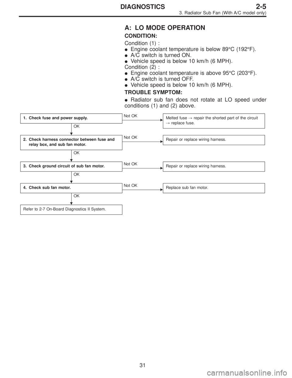
A: LO MODE OPERATION
CONDITION:
Condition (1) :
�Engine coolant temperature is below 89°C (192°F).
�A/C switch is turned ON.
�Vehicle speed is below 10 km/h (6 MPH).
Condition (2) :
�Engine coolant temperature is above 95°C (203°F).
�A/C switch is turned OFF.
�Vehicle speed is below 10 km/h (6 MPH).
TROUBLE SYMPTOM:
�Radiator sub fan does not rotate at LO speed under
conditions (1) and (2) above.
1. Check fuse and power supply.
OK
�Not OK
Melted fuse,repair the shorted part of the circuit
,replace fuse.
2. Check harness connector between fuse and
relay box, and sub fan motor.
OK
�Not OK
Repair or replace wiring harness.
3. Check ground circuit of sub fan motor.
OK
�Not OK
Repair or replace wiring harness.
4. Check sub fan motor.
OK
�Not OK
Replace sub fan motor.
Refer to 2-7 On-Board Diagnostics II System.
�
�
�
�
31
2-5DIAGNOSTICS
3. Radiator Sub Fan (With A/C model only)
Page 516 of 2890
 :
�Engine coolant temperature is below 89°C (192°F).
�A/C switch is turned ON.
�Vehicle speed is over 20 km/h (12 MPH).
Condition (2) :
�Engine coolant")
B: HI MODE OPERATION
CONDITION:
Condition (1) :
�Engine coolant temperature is below 89°C (192°F).
�A/C switch is turned ON.
�Vehicle speed is over 20 km/h (12 MPH).
Condition (2) :
�Engine coolant temperature is above 95°C (203°F).
�A/C switch is turned OFF.
�Vehicle speed is over 20 km/h (12 MPH).
Condition (3) :
�Engine coolant temperature is above 95°C (203°F).
�A/C switch is turned ON.
TROUBLE SYMPTOM:
�Radiator sub fan does not rotate at HI speed under con-
ditions (1), (2) and (3) above.
1. Check operation of sub fan motor LO mode.
OK
�Not OK
Check LO mode operation.
2. Check power supply to sub fan relay-2.
OK
�Not OK
Melted fuse (in A/C relay holder),repair the
shorted part of the circuit,replace fuse.
3. Check sub fan relay-2.
OK
�Not OK
Replace sub fan relay-2.
4. Check harness connector between sub fan
relay-2 and sub fan motor.
OK
�Not OK
Repair or replace wiring harness.
5. Check ground circuit of sub fan motor.
OK
�Not OK
Repair or replace wiring harness.
6. Check sub fan motor.
OK
�Not OK
Replace sub fan motor.
Refer to 2-7 On-Board Diagnostics II System.
�
�
�
�
�
�
33
2-5DIAGNOSTICS
3. Radiator Sub Fan (With A/C model only)
Page 519 of 2890

FUEL INJECTION SYSTEM2-7
Page
C COMPONENT PARTS....................................................................................2
1. Intake Manifold.........................................................................................2
2. Air Intake System.....................................................................................3
3. Air Cleaner ...............................................................................................4
W SERVICE PROCEDURE...............................................................................5
1. Air Cleaner and Air Intake Duct ...............................................................5
2. Mass Air Flow Sensor ..............................................................................6
3. Throttle Body............................................................................................7
4. Intake Manifold.........................................................................................8
5. Engine Coolant Temperature Sensor ....................................................18
6. Crankshaft Position Sensor ...................................................................18
7. Front Oxygen Sensor.............................................................................19
8. Rear Oxygen Sensor .............................................................................21
9. Throttle Position Sensor ........................................................................24
10. Camshaft Position Sensor .....................................................................25
11. Pressure Sensor (AT model)..................................................................25
12. Idle Air Control Solenoid Valve ..............................................................26
13. Pressure Sources Switching Solenoid Valve (AT model) ......................27
14. Fuel Injector ...........................................................................................28
15. Engine Control Module ..........................................................................28
16. Main Relay .............................................................................................30
17. Fuel Pump Relay ...................................................................................31
Page 520 of 2890

�
2Intake manifold gasket RH
(2200 cc model)
�
3Intake manifold gasket LH
(2500 cc model)
�
4Intake manifold gasket RH
(2500 cc")
1. Intake Manifold
B2M0739A
�1Intake manifold gasket LH
(2200 cc model)
�
2Intake manifold gasket RH
(2200 cc model)
�
3Intake manifold gasket LH
(2500 cc model)
�
4Intake manifold gasket RH
(2500 cc model)
�
5Fuel injector pipe insulator
�
6Fuel injector pipe
�
7O-ring A
�
8O-ring B
�
9Fuel injector
�
10Insulator
�
11Fuel injector cap
�
12Plate
�
13Sealing�
14Gasket
�
15Engine coolant hose B
�
16Air by-pass hose
�
17Idle air control solenoid valve
�
18Engine coolant hose A
�
19Nipple (AT model)
�
20Plug
�
21PCV valve
�
22Purge control solenoid valve
�
23Nipple
�
24BPT
�
25BPT holder bracket
�
26Back pressure hose
�
27EGR vacuum hose A
�
28EGR vacuum pipe
�
29EGR vacuum hose C
�
30EGR valve�
31Gasket
�
32EGR vacuum hose B
�
33EGR solenoid valve
�
34EGR pipe
�
35Collar
�
36Intake manifold
Tightening torque: N⋅m (kg-m, ft-lb)
T1: 3.4±0.5 (0.35±0.05, 2.5±0.4)
T2: 6.4±0.5 (0.65±0.05, 4.7±0.4)
T3: 16±1.5 (1.6±0.15, 11.6±1.1)
T4: 19±1 (1.9±0.1, 13.7±0.7)
T5: 19±1.5 (1.9±0.15, 13.7±1.1)
T6: 23±3 (2.3±0.3, 16.6±2.2)
T7: 25±2 (2.5±0.2, 18.1±1.4)
T8: 34±2 (3.5±0.2, 25.3±1.4)
2
2-7COMPONENT PARTS
1. Intake Manifold
Page 525 of 2890
B2M0154
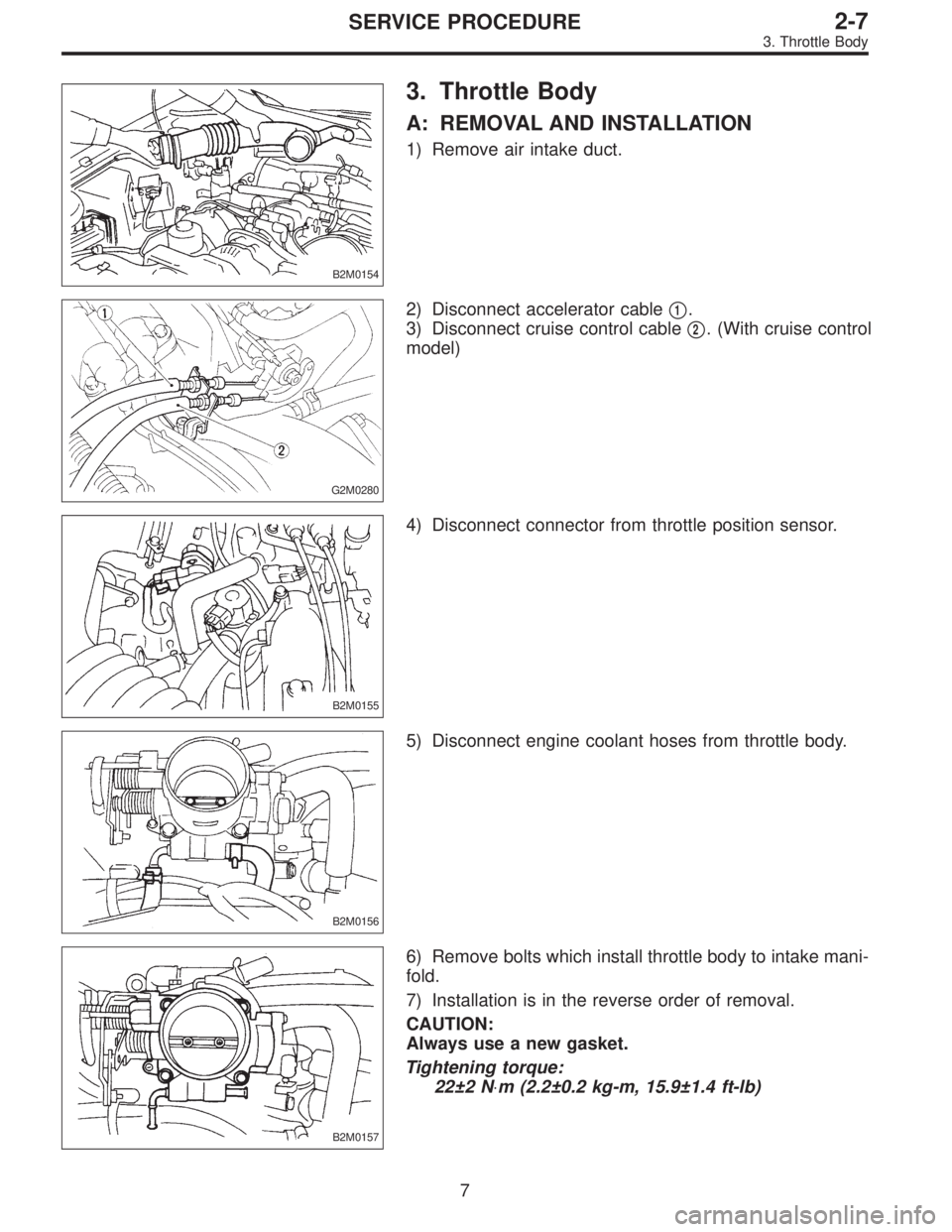
3. Throttle Body
A: REMOVAL AND INSTALLATION
1) Remove air intake duct.
G2M0280
2) Disconnect accelerator cable�1.
3) Disconnect cruise control cable�
2. (With cruise control
model)
B2M0155
4) Disconnect connector from throttle position sensor.
B2M0156
5) Disconnect engine coolant hoses from throttle body.
B2M0157
6) Remove bolts which install throttle body to intake mani-
fold.
7) Installation is in the reverse order of removal.
CAUTION:
Always use a new gasket.
Tightening torque:
22±2 N⋅m (2.2±0.2 kg-m, 15.9±1.4 ft-lb)
7
2-7SERVICE PROCEDURE
3. Throttle Body
Page 527 of 2890
B2M0334
(3) Remove bolts which install power steering pump
from bracket.
B2M0029
(4) Place power steering pump on the right side wheel
apron.
B6M0160
8) Disconnect spark plug cords from ignition coil.
H2M1246
9) Disconnect engine coolant hoses from throttle body.
H2M1259A
10) Disconnect engine coolant hose�1from idle air con-
trol solenoid valve.
11) Disconnect air by-pass hose�
2from idle air control
solenoid valve.
9
2-7SERVICE PROCEDURE
4. Intake Manifold
Page 528 of 2890
B2M0342
12) Disconnect brake booster hose.
B2M0343
13) Remove EGR pipe.
G2M0370
14) Disconnect canister hose from pipe.
B2M0019
15) Disconnect engine harness connectors from bulkhead
harness connectors.
B2M0345A
16) Disconnect connectors from engine coolant tempera-
ture sensor�
1and thermometer�2.
10
2-7SERVICE PROCEDURE
4. Intake Manifold
 Remove bolts which install power steering pump
from bracket.
B2M0029
(4) Place power steering pump on the right side wheel
apron.
B6M0160
8) Disconnect spark plug cords from ignition coil.")
 Disconnect brake booster hose.
B2M0343
13) Remove EGR pipe.
G2M0370
14) Disconnect canister hose from pipe.
B2M0019
15) Disconnect engine harness connectors from bulkhead
harness connector")