Page 384 of 2890
B2M0390A
(2) Apply fluid packing to matching surface of oil pump.
Fluid packing:
THREE BOND 1215 or equivalent
(3) Install oil pump on cylinder block. Be careful not to
damage oil seal during installation.
CAUTION:
�Do not forget to install O-ring and seal when install-
ing oil pump.
�Align flat surface of oil pump’s inner rotor with
crankshaft before installation.
G2M0628
9) Install engine coolant pump and gasket.
CAUTION:
�Be sure to use a new gasket.
�When installing engine coolant pump, tighten bolts
in two stages in numerical sequence as shown in Fig-
ure.
10) Install engine coolant pipe.
11) Install oil filter.
2. RELATED PARTS
1) Install cylinder head and intake manifold.
2) Install timing belt, camshaft sprocket and related parts.
74
2-3SERVICE PROCEDURE
7. Cylinder Block
Page 388 of 2890

2. Engine Noise
Valve lash adjusters may make clicking noise once engine
starts. It is normal if clicking noise ceases after a few min-
utes.
If clicking noise continues after a few minutes, check
engine oil level and add oil if necessary.
Then, do as follows to cease clicking noise.
1) Warm-up engine for five minutes.
2) Turn ignition switch OFF.
3) Connect test mode connector.
4) Start the engine and run it at approximately 2,000 rpm
for twenty minutes.
5) Turn ignition switch OFF.
6) Disconnect test mode connector.
7) Start the engine and check that clicking noise is ceased.
If noise still exists, conduct troubleshooting procedures in
accordance with the following table.
CAUTION:
Do not disconnect spark plug cord while engine is run-
ning.
Type of sound Condition Possible cause
Regular clicking soundSound increases as engine
speed increases.Valve mechanism is defective.
�Broken lash adjuster
�Worn valve rocker
�Worn camshaft
�Broken valve spring
�Worn valve lifter hole
Heavy and dull clankOil pressure is low.�Worn crankshaft main bearing
�Worn connecting rod bearing (big end)
Oil pressure is normal.�Loose flywheel mounting bolts
�Damaged engine mounting
High-pitched clank
(Spark knock)Sound is noticeable when
accelerating with an overload.�Ignition timing advanced
�Accumulation of carbon inside combustion chamber
�Wrong spark plug
�Improper gasoline
Clank when engine speed is
medium (1,000 to 2,000 rpm).Sound is reduced when fuel
injector connector of noisy
cylinder is disconnected.
(NOTE*)�Worn crankshaft main bearing
�Worn bearing at crankshaft end of connecting rod
Knocking sound when engine
is operating under idling speed
and engine is warm.Sound is reduced when fuel
injector connector of noisy
cylinder is disconnected.
(NOTE*)�Worn cylinder liner and piston ring
�Broken or stuck piston ring
�Worn piston pin and hole at piston end of connecting rod
Sound is not reduced if each
fuel injector connector is
disconnected in turn. (NOTE*)�Unusually worn valve lifter
�Worn cam gear
�Worn camshaft journal bore in crankcase
Squeaky sound—�Insufficient generator lubrication
Rubbing sound—�Defective generator brush and rotor contact
Gear scream when starting
engine—�Defective ignition starter switch
�Worn gear and starter pinion
Sound like polishing glass with
a dry cloth—�Loose drive belt
�Defective engine coolant pump shaft
78
2-3DIAGNOSTICS
2. Engine Noise
Page 397 of 2890
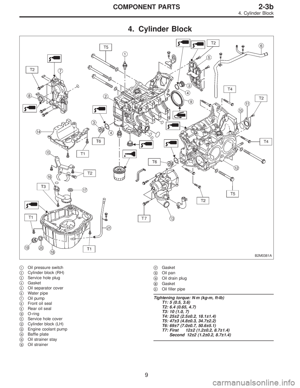
4. Cylinder Block
B2M0381A
�1Oil pressure switch
�
2Cylinder block (RH)
�
3Service hole plug
�
4Gasket
�
5Oil separator cover
�
6Water pipe
�
7Oil pump
�
8Front oil seal
�
9Rear oil seal
�
10O-ring
�
11Service hole cover
�
12Cylinder block (LH)
�
13Engine coolant pump
�
14Baffle plate
�
15Oil strainer stay
�
16Oil strainer�
17Gasket
�
18Oil pan
�
19Oil drain plug
�
20Gasket
�
21Oil filler pipe
Tightening torque: N⋅m (kg-m, ft-lb)
T1: 5 (0.5, 3.6)
T2: 6.4 (0.65, 4.7)
T3: 10 (1.0, 7)
T4: 25±2 (2.5±0.2, 18.1±1.4)
T5: 47±3 (4.8±0.3, 34.7±2.2)
T6: 69±7 (7.0±0.7, 50.6±5.1)
T7: First 12±2 (1.2±0.2, 8.7±1.4)
Second 12±2 (1.2±0.2, 8.7±1.4)
9
2-3bCOMPONENT PARTS
4. Cylinder Block
Page 399 of 2890
G2M0709
1. General Precautions
1) Before disassembling engine, place it on ST3.
ST1 498457000 ENGINE STAND ADAPTER RH
ST2 498457100 ENGINE STAND ADAPTER LH
ST3 499817000 ENGINE STAND
2) All parts should be thoroughly cleaned, paying special
attention to the engine oil passages, pistons and bearings.
3) Rotating parts and sliding parts such as piston, bearing
and gear should be coated with oil prior to assembly.
4) Be careful not to let oil, grease or coolant contact the
timing belt, clutch disc and flywheel.
5) All removed parts, if to be reused, should be reinstalled
in the original positions and directions.
6) Gaskets and lock washers must be replaced with new
ones. Liquid gasket should be used where specified to
prevent leakage.
7) Bolts, nuts and washers should be replaced with new
ones as required.
8) Even if necessary inspections have been made in
advance, proceed with assembly work while making
rechecks.
11
2-3bSERVICE PROCEDURE
1. General Precautions
Page 406 of 2890
B2M0737
7) Remove left-hand belt cover No. 2.
B2M0738
8) Remove right-hand belt cover No. 2.
B: INSPECTION
1. TIMING BELT
1) Check timing belt teeth for breaks, cracks, and wear. If
any fault is found, replace belt.
2) Check the condition of back side of belt; if any crack is
found, replace belt.
CAUTION:
�Be careful not to let oil, grease or coolant contact
the belt. Remove quickly and thoroughly if this hap-
pens.
G2M0115
�Do not bend the belt sharply.
Bending radius: h
60 mm (2.36 in) or more
18
2-3bSERVICE PROCEDURE
2. Timing Belt
Page 423 of 2890
4. Cylinder Head
A: REMOVAL
1. INTAKE MANIFOLD
1) Remove V-belt.
2) Remove generator, air conditioner compressor and
brackets.
3) Remove hoses and tubes from cylinder block.
4) Disconnect each connector and/or remove connector
bracket.
5) Remove coolant filler tank.
6) Remove intake manifold assembly and gasket.
7) Remove water pipe.
8) Remove crank angle sensor, cam angle sensor and
knock sensor.
9) Remove timing belt, camshaft sprockets and related
parts.
10) Remove rocker cover, camshafts and related parts.
2. CYLINDER HEAD
B2M0770A
35
2-3bSERVICE PROCEDURE
4. Cylinder Head
Page 433 of 2890
2) Install camshaft sprockets, timing belt and related parts.
B2M0702
B2M0703
3) Install engine coolant pipe.
CAUTION:
Use new gaskets.
45
2-3bSERVICE PROCEDURE
4. Cylinder Head
Page 434 of 2890
G2M0774
4) Install intake manifold.
CAUTION:
Use new gaskets.
5) Install coolant filler tank.
6) Install crankshaft position sensor, camshaft position
sensor and knock sensor. Use dry compressed air to
remove foreign particles before installing sensors.
7) Connect each connector and/or install connector
bracket.
8) Connect hoses and tubes to cylinder block.
9) Install brackets, generator and air conditioner compres-
sor.
10) Install V-belt.
46
2-3bSERVICE PROCEDURE
4. Cylinder Head
 Apply fluid packing to matching surface of oil pump.
Fluid packing:
THREE BOND 1215 or equivalent
(3) Install oil pump on cylinder block. Be careful not to
damage oil seal during installa")
 Before disassembling engine, place it on ST3.
ST1 498457000 ENGINE STAND ADAPTER RH
ST2 498457100 ENGINE STAND ADAPTER LH
ST3 499817000 ENGINE STAND
2) All parts shou")
 Remove left-hand belt cover No. 2.
B2M0738
8) Remove right-hand belt cover No. 2.
B: INSPECTION
1. TIMING BELT
1) Check timing belt teeth for breaks, cracks, and wear. If
any fault is found")
 Remove V-belt.
2) Remove generator, air conditioner compressor and
brackets.
3) Remove hoses and tubes from cylinder block.
4) Disconnect each connect")
![SUBARU LEGACY 1996 Service Repair Manual 2) Install camshaft sprockets, timing belt and related parts.
<Ref. to 2-3b [W2C0].>
B2M0702
B2M0703
3) Install engine coolant pipe.
CAUTION:
Use new gaskets.
45
2-3bSERVICE PROCEDURE
4. Cylinder Head](/manual-img/17/57433/w960_57433-432.png "SUBARU LEGACY 1996 Service Repair Manual 2) Install camshaft sprockets, timing belt and related parts.
<Ref. to 2-3b [W2C0].>
B2M0702
B2M0703
3) Install engine coolant pipe.
CAUTION:
Use new gaskets.
45
2-3bSERVICE PROCEDURE
4. Cylinder Head")
 Install intake manifold.
CAUTION:
Use new gaskets.
5) Install coolant filler tank.
6) Install crankshaft position sensor, camshaft position
sensor and knock sensor. Use dry compressed air t")