Page 533 of 2890
G2M0408
4) Connect connector to crankshaft position sensor.
G2M0416
5) Connect connector to camshaft position sensor.
B2M0346
6) Connect connector to knock sensor.
B2M0345A
7) Connect connectors to engine coolant temperature sen-
sor�
1and thermometer�2.
B2M0019
8) Connect engine harness connector to bulkhead har-
ness connectors.
15
2-7SERVICE PROCEDURE
4. Intake Manifold
Page 534 of 2890
G2M0370
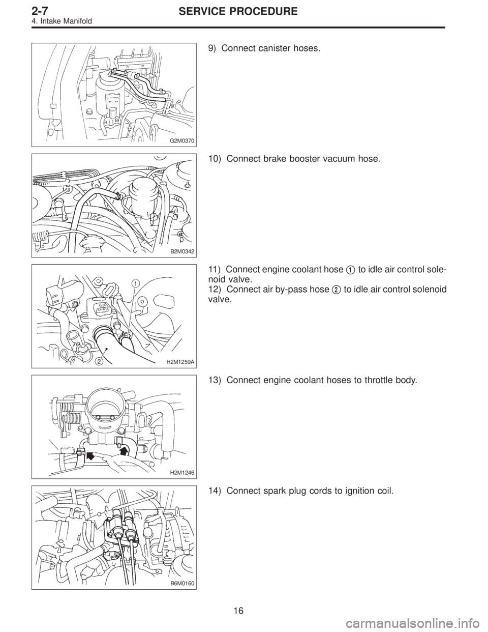
9) Connect canister hoses.
B2M0342
10) Connect brake booster vacuum hose.
H2M1259A
11) Connect engine coolant hose�1to idle air control sole-
noid valve.
12) Connect air by-pass hose�
2to idle air control solenoid
valve.
H2M1246
13) Connect engine coolant hoses to throttle body.
B6M0160
14) Connect spark plug cords to ignition coil.
16
2-7SERVICE PROCEDURE
4. Intake Manifold
Page 536 of 2890
B2M0154
18) Install air cleaner element, air cleaner upper cover and
air intake duct.
19) Connect connector to mass air flow sensor.
B2M0154
5. Engine Coolant Temperature Sensor
A: REMOVAL AND INSTALLATION
1) Remove air intake duct.
G2M0407
2) Disconnect connector from engine coolant temperature
sensor.
3) Remove engine coolant temperature sensor.
G2M0407
4) Installation is in the reverse order of removal.
Tightening torque:
25±3 N⋅m (2.5±0.3 kg-m, 18.1±2.2 ft-lb)
G2M0408
6. Crankshaft Position Sensor
A: REMOVAL AND INSTALLATION
1) Remove bolt which install crankshaft position sensor to
cylinder block.
18
2-7SERVICE PROCEDURE
4. Intake Manifold - 6. Crankshaft Position Sensor
Page 544 of 2890
B2M0164
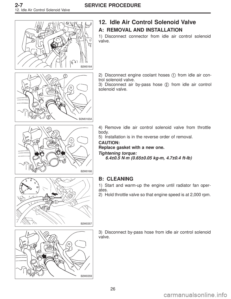
12. Idle Air Control Solenoid Valve
A: REMOVAL AND INSTALLATION
1) Disconnect connector from idle air control solenoid
valve.
B2M0165A
2) Disconnect engine coolant hoses�1from idle air con-
trol solenoid valve.
3) Disconnect air by-pass hose�
2from idle air control
solenoid valve.
B2M0166
4) Remove idle air control solenoid valve from throttle
body.
5) Installation is in the reverse order of removal.
CAUTION:
Replace gasket with a new one.
Tightening torque:
6.4±0.5 N⋅m (0.65±0.05 kg-m, 4.7±0.4 ft-lb)
B2M0357
B: CLEANING
1) Start and warm-up the engine until radiator fan oper-
ates.
2) Hold throttle valve so that engine speed is at 2,000 rpm.
B2M0359
3) Disconnect by-pass hose from idle air control solenoid
valve.
26
2-7SERVICE PROCEDURE
12. Idle Air Control Solenoid Valve
Page 596 of 2890

G2M0213
C: INSTALLATION
Installation is in the reverse order of removal.
CAUTION:
�Replace gasket with a new one.
�When installing engine coolant pump, tighten bolts
in two stages in numerical sequence as shown in fig-
ure.
Tightening torque:
10
+4
�0N⋅m (1.0+0.4
�0kg-m, 7.2+2.9
�0ft-lb)
G2M0214
3. Thermostat
A: REMOVAL AND INSTALLATION
1) Drain engine coolant.
Set container under the vehicle, and remove drain cock
from radiator.
2) Disconnect radiator outlet hose from thermostat cover.
3) Remove thermostat cover and gasket, and pull out the
thermostat.
G2M0227
4) Install the thermostat in the intake manifold, and install
the thermostat cover together with a gasket.
CAUTION:
�When reinstalling the thermostat, use a new gasket.
�The thermostat must be installed with the jiggle pin
upward.
�In this time, set the jiggle pin of thermostat for front
side.
G2M0215
B: INSPECTION
Replace the thermostat if the valve does not close com-
pletely at an ambient temperature or if the following test
shows unsatisfactory results.
Immerse the thermostat and a thermometer in water. Raise
water temperature gradually, and measure the temperature
and valve lift when the valve begins to open and when the
valve is fully opened. During the test, agitate the water for
even temperature distribution. The measurement should
be to the specification.
Starts to open:
76.0—80.0°C (169—176°F)
Fully opens:
91°C (196°F)
12
2-5SERVICE PROCEDURE
2. Engine Coolant Pump - 3. Thermostat
Page 597 of 2890
B2M0015A
4. Radiator
A: REMOVAL
1) Disconnect battery cables and remove battery from
body.
2) Drain engine coolant.
Set container under the vehicle, and remove drain cock
from radiator.
B2M0304
3) Disconnect radiator outlet hose from thermostat cover.
4) Disconnect ATF cooler hoses from radiator. (AT model)
B2M0017
5) Remove V-belt cover.
B2M0305
6) Disconnect inlet hose from radiator.
G2M0263
7) Disconnect connectors of radiator main fan and sub fan
motor.
13
2-5SERVICE PROCEDURE
4. Radiator
Page 602 of 2890
B2M0323
5) Remove radiator fan motor assembly.
6) Remove fan motor from shroud.
B: INSTALLATION
Installation is in the reverse order of removal procedures.
Do the following:
1) Before installing radiator fan motor, apply a coat of seal-
ant to threads and tighten nuts.
2) Make sure radiator fan does not come into contact with
shroud when installed.
3) After installation, make sure there is no unusual noise
or vibration when fan is rotated.
G6M0095
7. Engine Coolant Pipe
A: REMOVAL
1) Release fuel pressure.
2) Disconnect ground cable from the battery.
B2M0015A
3) Drain engine coolant completely.
B2M0160
4) Remove intake manifold.
17
2-5SERVICE PROCEDURE
6. Radiator Fan and Fan Motor - 7. Engine Coolant Pipe
Page 603 of 2890
B2M0323
5) Remove radiator fan motor assembly.
6) Remove fan motor from shroud.
B: INSTALLATION
Installation is in the reverse order of removal procedures.
Do the following:
1) Before installing radiator fan motor, apply a coat of seal-
ant to threads and tighten nuts.
2) Make sure radiator fan does not come into contact with
shroud when installed.
3) After installation, make sure there is no unusual noise
or vibration when fan is rotated.
G6M0095
7. Engine Coolant Pipe
A: REMOVAL
1) Release fuel pressure.
2) Disconnect ground cable from the battery.
B2M0015A
3) Drain engine coolant completely.
B2M0160
4) Remove intake manifold.
17
2-5SERVICE PROCEDURE
6. Radiator Fan and Fan Motor - 7. Engine Coolant Pipe
 Connect connector to crankshaft position sensor.
G2M0416
5) Connect connector to camshaft position sensor.
B2M0346
6) Connect connector to knock sensor.
B2M0345A
7) Connect connectors to en")
 Install air cleaner element, air cleaner upper cover and
air intake duct.
19) Connect connector to mass air flow sensor.
B2M0154
5. Engine Coolant Temperature Sensor
A: REMOVAL AND INSTALL")
 Disconnect battery cables and remove battery from
body.
2) Drain engine coolant.
Set container under the vehicle, and remove drain cock
from radiator.
B2M0304
3) Dis")
 Remove radiator fan motor assembly.
6) Remove fan motor from shroud.
B: INSTALLATION
Installation is in the reverse order of removal procedures.
Do the following:
1) Before installing radia")
 Remove radiator fan motor assembly.
6) Remove fan motor from shroud.
B: INSTALLATION
Installation is in the reverse order of removal procedures.
Do the following:
1) Before installing radia")