Page 1838 of 2890
 I/O SIGNAL
OBD0092A
ContentConnector
No.Terminal
No.Signal (V)
Note
Ignition SW ON
(Engine OFF)Engine ON (Idling)
Crankshaft
position
sensorSignal (+)")
5. Specified Data
1. ENGINE CONTROL MODULE (ECM) I/O SIGNAL
OBD0092A
ContentConnector
No.Terminal
No.Signal (V)
Note
Ignition SW ON
(Engine OFF)Engine ON (Idling)
Crankshaft
position
sensorSignal (+) B84 8 0�7—+7 Sensor output waveform
Signal (�) B84 29 0 0—
Shield B84 54 0 0—
Camshaft
position
sensorSignal (+) B84 7 0�7—+7 Sensor output waveform
Signal (�) B84 28 0 0—
Shield B84 54 0 0—
Mass air
flow sensorSignal B84 5 0—0.3 0.8—1.2—
Shield B84 57 0 0—
GND B84 20 0 0—
Throttle
position
sensorSignal B84 6Fully closed: 0.2—1.0
Fully opened: 4.2—4.7—
Power
supplyB84 21 5 5—
GND B84 20 0 0—
Front
oxygen
sensorSignal B84 23 0 0—0.9—
Shield B84 56 0 0—
Rear
oxygen
sensorSignal B84 24 0 0—0.9—
Shield B84 56 0 0—
Engine coolant
temperature sensorB84 22 1.0—1.4 1.0—1.4 After warm-up
Vehicle speed sensor 2 B84 83 0 or 5 0 or 5“5”and“0”are repeatedly
displayed when vehicle is
driven.
Starter switch B84 86 0 0 Cranking: 8 to 14
A/C switch B84 60ON: 10—13
OFF: 0ON: 13—14
OFF: 0—
Ignition switch B84 85 10—13 13—14—
Neutral position switch
(MT)
B84 82ON: 5.0±0.5
OFF: 0�On MT model; switch is ON
when gear is in neutral position.
Neutral position switch
(AT)ON: 0
OFF: 5.0±0.5�On AT model; switch is ON when
shift is in“N”or“P”position.
Test mode connector B84 84 5 5 When connected: 0
70
2-7ON-BOARD DIAGNOSTICS II SYSTEM
5. Specified Data
Page 1886 of 2890

Throttle position sensor
Crankshaft position sensor & Camshaft po")
9. General Diagnostics Table
1. FOR ENGINE
12345678910111213
Problem parts
Mass air flow sensor
Engine coolant temperature sensor (*1)
Throttle position sensor
Crankshaft position sensor & Camshaft position sensor (*2)
Idle air control solenoid valve
Knock sensor
Purge control solenoid valve
EGR valve
Fuel injection parts (*3)
Ignition parts (*4)
Fuel pump and relay
A/C switch and A/C cut relay
Engine torque control signal circuitSymptom
1 Engine stalls during idling.�� � � ���
2 Rough idling�� � � � �
3 Engine does not return to idle.���
4 Poor acceleration�� � � ���
5Engine stalls or engine sags or hesi-
tates at acceleration.�� � � ��� �
6 Surge�� � �� �
7 Spark knock����
8 After burning in exhaust system�� � �
*1: The mark,�, indicates the symptom occurring only in cold temperatures.
*2: For items with the mark,�, ensure the secure installation of crankshaft position sensor and camshaft position sensor. Replacement is
not necessary.
*3: Check fuel injector, fuel pressure regulator and fuel filter.
*4: Check ignitor, ignition coil and spark plug.
NOTE:
Malfunction of parts other than the above is also possible. Refer to 1. Engine Trouble in General [K100] in Repair Section 2-3 or 2-3b of
the Service Manual.
11 8
2-7ON-BOARD DIAGNOSTICS II SYSTEM
9. General Diagnostics Table
Page 1891 of 2890
 LIST
DTC
No.Abbreviation
(Subaru select monitor)Item Page
P0100 QA Mass air flow sensor circuit malfunction 125
P0101 QA
—R M")
10. Diagnostics Chart with Trouble
Code
A: DIAGNOSTIC TROUBLE CODE (DTC) LIST
DTC
No.Abbreviation
(Subaru select monitor)Item Page
P0100 QA Mass air flow sensor circuit malfunction 125
P0101 QA
—R Mass air flow sensor circuit range/performance problem 132
P0105 P
—S Pressure sensor circuit malfunction 134
P0106 PS
—R Pressure sensor circuit range/performance problem 142
P0115 TW Engine coolant temperature sensor circuit malfunction 147
P0120 THV Throttle position sensor circuit malfunction 151
P0121 TH
—R Throttle position sensor circuit range/performance problem 157
P0125 TW
—CL Insufficient coolant temperature for closed loop fuel control 159
P0130 FO2
—V Front oxygen sensor circuit malfunction 161
P0133 FO2
—R Front oxygen sensor circuit slow response 164
P0135 FO2H Front oxygen sensor heater circuit malfunction 166
P0136 RO2
—V Rear oxygen sensor circuit malfunction 172
P0139 RO2
—R Rear oxygen sensor circuit slow response 177
P0141 RO2H Rear oxygen sensor heater circuit malfunction 179
P0170 FUEL Fuel trim malfunction 185
P0180 TNKT Fuel temperature sensor A circuit malfunction 190
P0181 TNKT
—F Fuel temperature sensor A circuit range/performance problem 195
P0201 INJ1 Fuel injector circuit malfunction - #1
197 P0202 INJ2 Fuel injector circuit malfunction - #2
P0203 INJ3 Fuel injector circuit malfunction - #3
P0204 INJ4 Fuel injector circuit malfunction - #4
P0301 MIS
—1 Cylinder 1 misfire detected
203 P0302 MIS
—2 Cylinder 2 misfire detected
P0303 MIS
—3 Cylinder 3 misfire detected
P0304 MIS
—4 Cylinder 4 misfire detected
P0325 KNOCK Knock sensor circuit malfunction 211
P0335 CRANK Crankshaft position sensor circuit malfunction 215
P0340 CAM Camshaft position sensor circuit malfunction 218
P0400 EGR Exhaust gas recirculation flow malfunction 221
P0403 EGRSOL Exhaust gas recirculation circuit malfunction 227
P0420 CAT Catalyst system efficiency below threshold 233
P0440 EVAP Evaporative emission control system malfunction 236
P0441 CPC
—F Evaporative emission control system incorrect purge flow 241
P0443 CPC Evaporative emission control system purge control valve circuit malfunction 244
P0446 VCMSOL Evaporative emission control system vent control malfunction 249
P0450 TNKP Evaporative emission control system pressure sensor malfunction 255
P0451 TNKP
—F Evaporative emission control system pressure sensor range/performance problem 264
123
2-7ON-BOARD DIAGNOSTICS II SYSTEM
10. Diagnostics Chart with Trouble Code
Page 1915 of 2890
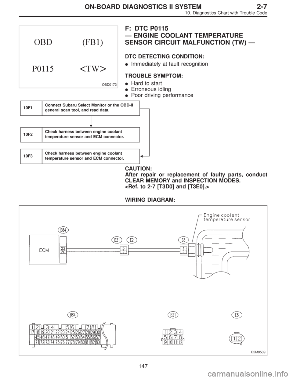
OBD0172
F: DTC P0115
—ENGINE COOLANT TEMPERATURE
SENSOR CIRCUIT MALFUNCTION (TW)—
DTC DETECTING CONDITION:
�Immediately at fault recognition
TROUBLE SYMPTOM:
�Hard to start
�Erroneous idling
�Poor driving performance
10F1Connect Subaru Select Monitor or the OBD-II
general scan tool, and read data.
�
10F2Check harness between engine coolant
temperature sensor and ECM connector.
10F3Check harness between engine coolant
temperature sensor and ECM connector.
CAUTION:
After repair or replacement of faulty parts, conduct
CLEAR MEMORY and INSPECTION MODES.
WIRING DIAGRAM:
B2M0539
�
147
2-7ON-BOARD DIAGNOSTICS II SYSTEM
10. Diagnostics Chart with Trouble Code
Page 1916 of 2890
 Turn ignition switch to OFF.
2) Connect Subaru Select Monitor or the OBD-II general
scan tool to data link")
OBD0145A
10F1CONNECT SUBARU SELECT MONITOR
OR THE OBD-II GENERAL SCAN TOOL,
AND READ DATA.
1) Turn ignition switch to OFF.
2) Connect Subaru Select Monitor or the OBD-II general
scan tool to data link connector.
3) Turn ignition switch to ON and Subaru Select Monitor or
OBD-II general scan tool switch to ON.
4) Start engine.
B2M0479
5) Read data on Subaru Select Monitor or OBD-II general
scan tool.
�Subaru Select Monitor
Designate mode using function key.
Function mode: F04
�F04: Water temperature is indicated in“°C”and“°F”.
: Is the value greater than 150°Cor300°Fin
function mode F04?
: Go to step10F2.
: Go to next.
B2M0479
: Is the value less than�40°Cor�40°Fin
function mode F04?
: Go to step10F3.
: Repair poor contact.
NOTE:
In this case, repair the following:
�Poor contact in engine coolant temperature sensor
�Poor contact in ECM
�Poor contact in coupling connector (B21)
�OBD-II general scan tool
For detailed operation procedures, refer to the OBD-II Gen-
eral Scan Tool Instruction Manual.
148
2-7ON-BOARD DIAGNOSTICS II SYSTEM
10. Diagnostics Chart with Trouble Code
Page 1917 of 2890
 Turn ignition switch to OFF.
2) Remove idle air control solenoid valve by-pass air hose.
3) Disconnect connec")
OBD0618A
10F2CHECK HARNESS BETWEEN ENGINE
COOLANT TEMPERATURE SENSOR AND
ECM CONNECTOR.
1) Turn ignition switch to OFF.
2) Remove idle air control solenoid valve by-pass air hose.
3) Disconnect connector from engine coolant temperature
sensor.
OBD0145A
4) Connect Subaru Select Monitor or the OBD-II general
scan tool to data link connector.
5) Turn ignition switch and Subaru Select Monitor or
OBD-II general scan tool switch to ON.
B2M0479
6) Read data on Subaru Select Monitor or the OBD-II gen-
eral scan tool.
�Subaru Select Monitor
Designate mode using function key.
Function mode: F04
�F04: Water temperature is indicated in“°C”and“°F”.
: Is the value less than�40°Cor�40°Fin
function mode F04?
: Replace engine coolant temperature sensor.
: Repair short circuit in harness between engine
coolant temperature sensor and ECM connector.
�OBD-II general scan tool
For detailed operation procedures, refer to the OBD-II Gen-
eral Scan Tool Instruction Manual.
149
2-7ON-BOARD DIAGNOSTICS II SYSTEM
10. Diagnostics Chart with Trouble Code
Page 1918 of 2890
 Turn ignition switch to OFF.
2) Remove idle air control solenoid valve by-pass air hose.
3) Disconnect connec")
OBD0618A
10F3CHECK HARNESS BETWEEN ENGINE
COOLANT TEMPERATURE SENSOR AND
ECM CONNECTOR.
1) Turn ignition switch to OFF.
2) Remove idle air control solenoid valve by-pass air hose.
3) Disconnect connector from engine coolant temperature
sensor.
4) Turn ignition switch to ON.
OBD0696A
5) Measure voltage between engine coolant temperature
sensor connector and engine ground.
: Connector & terminal
(E8) No. 1 (+)—Engine ground (�):
Is the voltage more than 4 V?
: Go to next step 6).
: Repair harness and connector.
NOTE:
In this case, repair the following:
�Open circuit in harness between ECM and engine cool-
ant temperature sensor connector
�Poor contact in engine coolant temperature sensor con-
nector
�Poor contact in ECM connector
�Poor contact in coupling connector (B21)
OBD0697A
6) Turn ignition switch to OFF.
7) Measure resistance of harness between engine coolant
temperature sensor connector and engine ground.
: Connector & terminal
(E8) No. 2—Engine ground:
Is the resistance less than 5Ω?
: Replace engine coolant temperature sensor.
: Repair harness and connector.
NOTE:
In this case, repair the following:
�Open circuit in harness between ECM and engine cool-
ant temperature sensor connector
�Poor contact in engine coolant temperature sensor con-
nector
�Poor contact in ECM connector
�Poor contact in coupling connector (B21)
150
2-7ON-BOARD DIAGNOSTICS II SYSTEM
10. Diagnostics Chart with Trouble Code
Page 1927 of 2890
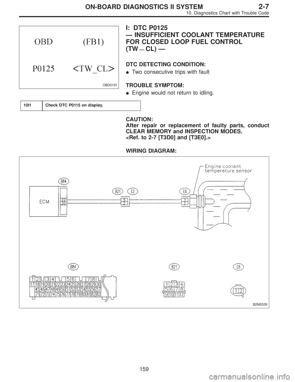
OBD0191
I: DTC P0125
—INSUFFICIENT COOLANT TEMPERATURE
FOR CLOSED LOOP FUEL CONTROL
(TW
—CL)—
DTC DETECTING CONDITION:
�Two consecutive trips with fault
TROUBLE SYMPTOM:
�Engine would not return to idling.
10I1Check DTC P0115 on display.
CAUTION:
After repair or replacement of faulty parts, conduct
CLEAR MEMORY and INSPECTION MODES.
WIRING DIAGRAM:
B2M0539
159
2-7ON-BOARD DIAGNOSTICS II SYSTEM
10. Diagnostics Chart with Trouble Code