1996 ACURA RL KA9 lock
[x] Cancel search: lockPage 1044 of 1954
Rear Suspensio n
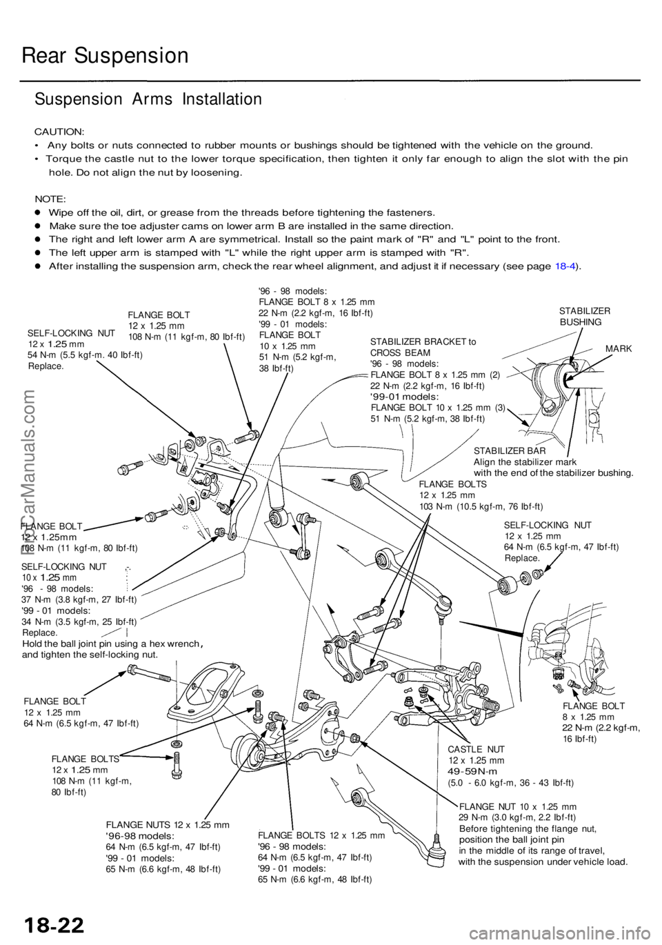
Suspension Arm s Installatio n
CAUTION:
• An y bolt s o r nut s connecte d to rubbe r mount s o r bushing s shoul d b e tightene d wit h th e vehicl e o n th e ground .
• Torqu e th e castl e nu t t o th e lowe r torqu e specification , the n tighte n it onl y fa r enoug h t o alig n th e slo t wit h th e pi n
hole . D o no t alig n th e nu t b y loosening .
NOTE:
Wipe of f th e oil , dirt , o r greas e fro m th e thread s befor e tightenin g th e fasteners .
Mak e sur e th e to e adjuste r cam s o n lowe r ar m B ar e installe d in th e sam e direction .
Th e righ t an d lef t lowe r ar m A ar e symmetrical . Instal l s o th e pain t mar k o f "R " an d "L " poin t t o th e front .
Th e lef t uppe r ar m is stampe d wit h "L " whil e th e righ t uppe r ar m is stampe d wit h "R" .
Afte r installin g th e suspensio n arm , chec k th e rea r whee l alignment , an d adjus t i t i f necessar y (se e pag e 18-4 ).
'9 6 - 9 8 models :
FLANG E BOL T 8 x 1.2 5 m m
2 2 N- m (2. 2 kgf-m , 1 6 Ibf-ft )
'9 9 - 0 1 models :
FLANG E BOL T
10 x 1.2 5 mm51 N- m (5. 2 kgf-m ,
3 8 Ibf-ft )
STABILIZE RBUSHING
STABILIZE R BRACKE T to
CROS S BEA M
'9 6 - 9 8 models :
FLANG E BOL T 8 x 1.25 m m (2 )
2 2 N- m (2. 2 kgf-m , 1 6 Ibf-ft )
'99-01 models :FLANGE BOL T 1 0 x 1.2 5 m m (3 )
5 1 N- m (5. 2 kgf-m , 3 8 Ibf-ft )
FLANG E BOL T
12 x 1.25m m108 N- m (1 1 kgf-m , 8 0 Ibf-ft )
SELF-LOCKIN G NU T ,- .
10 x 1.2 5 mm :'96 - 98 models :
3 7 N- m (3. 8 kgf-m , 2 7 Ibf-ft )
'99 - 0 1 models :34 N- m (3. 5 kgf-m , 2 5 Ibf-ft )
Replace .
Hold th e bal l join t pi n usin g a hex wrenc hand tighte n th e self-lockin g nut .
FLANG E BOL T12 x 1.2 5 mm64 N- m (6. 5 kgf-m , 4 7 Ibf-ft )
FLANG E BOLT S
12 x 1.2 5 mm108 N- m (1 1 kgf-m ,
8 0 Ibf-ft )
FLANG E NUT S 1 2 x 1.2 5 m m'96-9 8 models :64 N- m (6. 5 kgf-m , 4 7 Ibf-ft )'99 - 0 1 models :65 N- m (6. 6 kgf-m , 4 8 Ibf-ft ) STABILIZE
R BA R
Alig n th e stabilize r mar kwith th e en d o f th e stabilize r bushing .FLANGE BOLT S12 x 1.2 5 mm103 N- m (10. 5 kgf-m , 7 6 Ibf-ft )
SELF-LOCKIN G NU T
12 x 1.2 5 mm64 N- m (6. 5 kgf-m , 4 7 Ibf-ft )Replace .
MARK
FLANG E BOL T
8 x 1.2 5 mm22 N- m (2. 2 kgf-m ,16 Ibf-ft )
FLANG E BOLT S 1 2 x 1.2 5 m m
'96 - 9 8 models :64 N- m (6. 5 kgf-m , 4 7 Ibf-ft )'99 - 0 1 models :65 N- m (6. 6 kgf-m , 4 8 Ibf-ft ) CASTL
E NU T
12 x 1.2 5 mm49 - 5 9 N- m(5. 0 - 6. 0 kgf-m , 3 6 - 4 3 Ibf-ft )
FLANG E NU T 1 0 x 1.2 5 m m
2 9 N- m (3. 0 kgf-m , 2. 2 Ibf-ft )
Before tightenin g th e flang e nut ,positio n th e bal l join t pi nin th e middl e o f it s rang e o f travel ,with th e suspensio n unde r vehicl e load .
SELF-LOCKIN G NU T12 x 1.2 5 mm54 N- m (5. 5 kgf-m . 4 0 Ibf-ft )Replace .
FLANGE BOL T12 x 1.2 5 mm108 N- m (1 1 kgf-m , 8 0 Ibf-ft )
ProCarManuals.com
Page 1046 of 1954
Rear Damper
Disassembly/Inspection
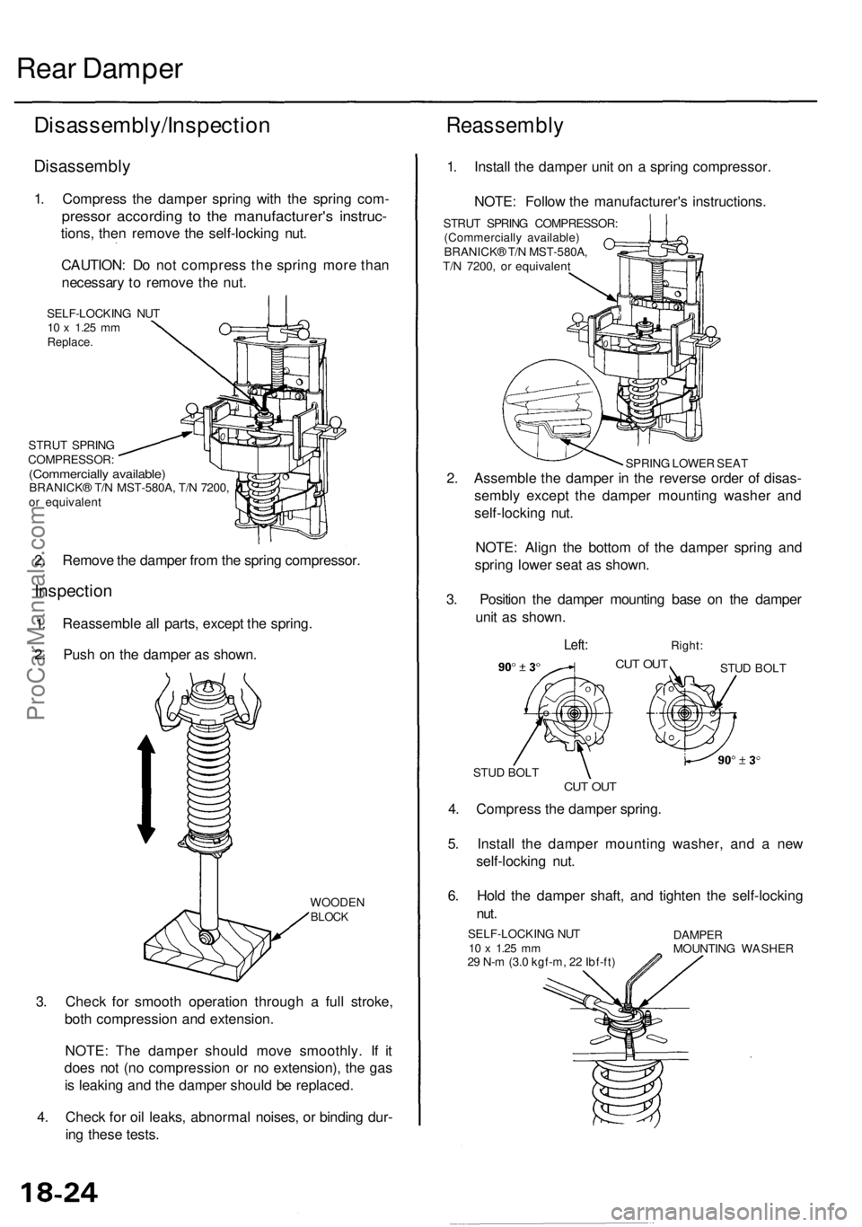
Disassembly
1. Compress the damper spring with the spring com-
pressor according to the manufacturer's instruc-
tions, then remove the self-locking nut.
CAUTION: Do not compress the spring more than
necessary to remove the nut.
SELF-LOCKING NUT
10 x
1.25
mm
Replace.
STRUT SPRING
COMPRESSOR:
(Commercially available)
BRANICK® T/N MST-580A, T/N 7200,
or equivalent
2. Remove the damper from the spring compressor.
Inspection
1. Reassemble all parts, except the spring.
2. Push on the damper as shown.
WOODEN
BLOCK
3. Check for smooth operation through a full stroke,
both compression and extension.
NOTE: The damper should move smoothly. If it
does not (no compression or no extension), the gas
is leaking and the damper should be replaced.
4. Check for oil leaks, abnormal noises, or binding dur-
ing these tests.
Reassembly
1. Install the damper unit on a spring compressor.
NOTE: Follow the manufacturer's instructions.
STRUT SPRING COMPRESSOR:
(Commercially available)
BRANICK® T/N MST-580A,
T/N 7200, or equivalent
SPRING LOWER SEAT
2. Assemble the damper in the reverse order of disas-
sembly except the damper mounting washer and
self-locking nut.
NOTE: Align the bottom of the damper spring and
spring lower seat as shown.
3. Position the damper mounting base on the damper
unit as shown.
Left:
Right:
CUT OUT
STUD BOLT
CUT OUT
STUD BOLT
4. Compress the damper spring.
5. Install the damper mounting washer, and a new
self-locking nut.
6. Hold the damper shaft, and tighten the self-locking
nut.
SELF-LOCKING NUT
10 x
1.25
mm
29 N-m (3.0 kgf-m, 22 Ibf-ft)
DAMPER
MOUNTING WASHERProCarManuals.com
Page 1051 of 1954
Inspection and Adjustment
Brake Pedal
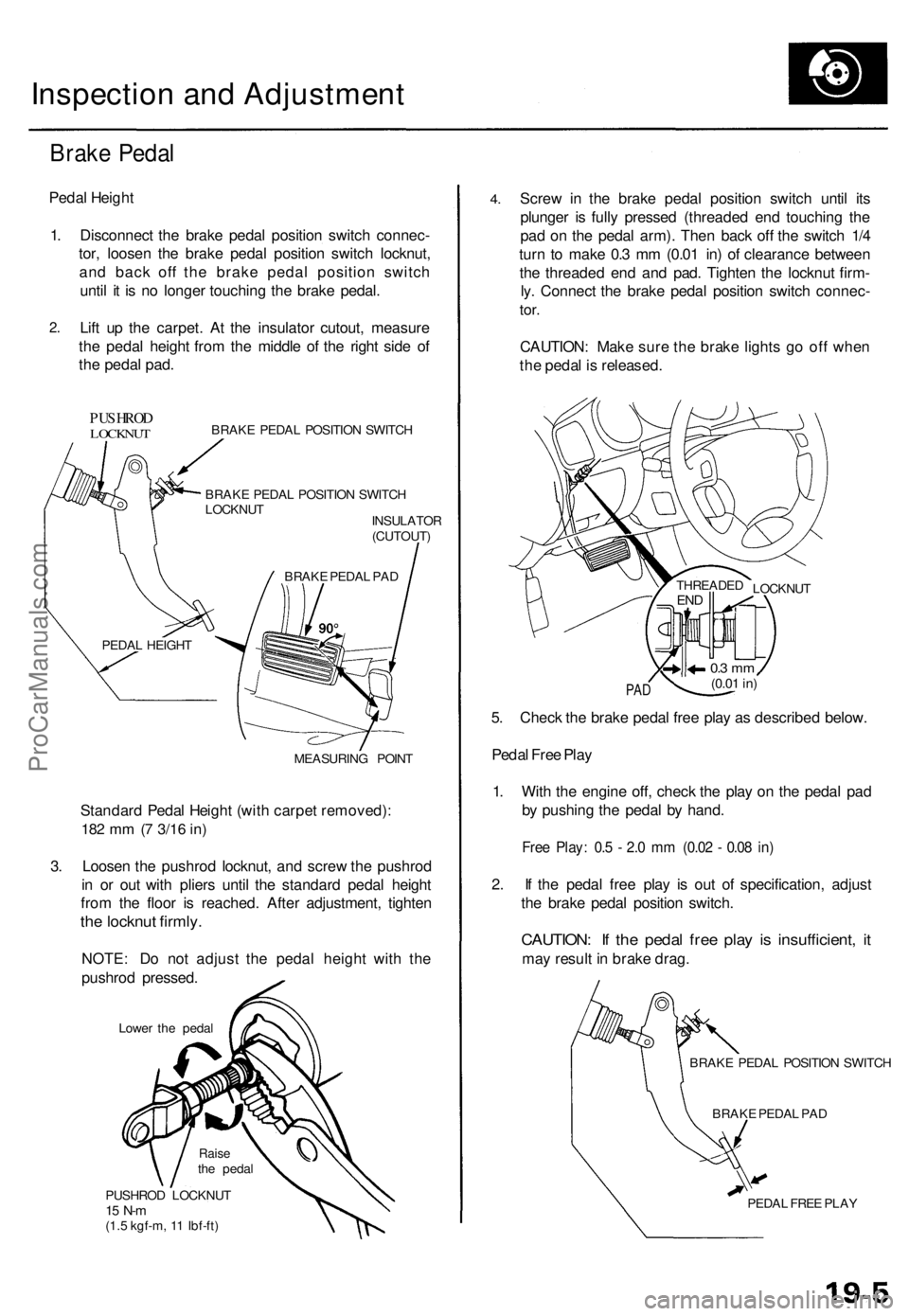
Pedal Height
1. Disconnect the brake pedal position switch connec-
tor, loosen the brake pedal position switch locknut,
and back off the brake pedal position switch
until it is no longer touching the brake pedal.
2.
Lift up the carpet. At the insulator cutout, measure
the pedal height from the middle of the right side of
the pedal pad.
PUSHROD
LOCKNUT
BRAKE PEDAL POSITION SWITCH
BRAKE PEDAL POSITION SWITCH
LOCKNUT
INSULATOR
(CUTOUT)
MEASURING POINT
Standard Pedal Height (with carpet removed):
182 mm (7
3/16
in)
3. Loosen the pushrod locknut, and screw the pushrod
in or out with pliers until the standard pedal height
from the floor is reached. After adjustment, tighten
the locknut firmly.
NOTE: Do not adjust the pedal height with the
pushrod pressed.
Lower the pedal
PUSHROD LOCKNUT
15 N-m
(1.5 kgf-m, 11 Ibf-ft)
4.
Screw in the brake pedal position switch until its
plunger is fully pressed (threaded end touching the
pad on the pedal arm). Then back off the switch 1/4
turn to make 0.3 mm (0.01 in) of clearance between
the threaded end and pad. Tighten the locknut firm-
ly. Connect the brake pedal position switch connec-
tor.
CAUTION: Make sure the brake lights go off when
the pedal is released.
PAD
5. Check the brake pedal free play as described below.
Pedal Free Play
1. With the engine off, check the play on the pedal pad
by pushing the pedal by hand.
Free Play: 0.5 - 2.0 mm (0.02 - 0.08 in)
2. If the pedal free play is out of specification, adjust
the brake pedal position switch.
CAUTION: If the pedal free play is insufficient, it
may result in brake drag.
BRAKE PEDAL POSITION SWITCH
BRAKE PEDAL PAD
PEDAL FREE PLAY
LOCKNUT
THREADED
END
0.3 mm
(0.01
in)
BRAKE PEDAL PAD
PEDAL HEIGHT
Raise
the pedalProCarManuals.com
Page 1052 of 1954
Inspection an d Adjustmen t
Parking Brak e Peda l
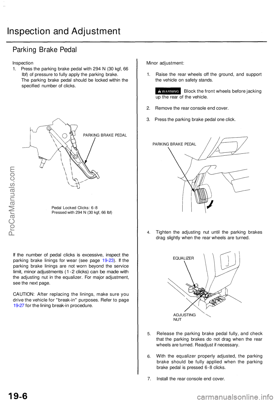
Inspectio n
1 . Pres s th e parkin g brak e peda l wit h 29 4 N (3 0 kgf , 6 6
Ibf ) o f pressur e to full y appl y th e parkin g brake .
Th e parkin g brak e peda l shoul d b e locke d withi n th e
specifie d numbe r o f clicks .
PARKIN G BRAK E PEDA L
Pedal Locke d Clicks : 6- 8Presse d wit h 29 4 N (3 0 kgf , 6 6 Ibf )
If th e numbe r o f peda l click s i s excessive , inspec t th e
parkin g brak e lining s fo r wea r (se e pag e 19-23 ). I f th e
parkin g brak e lining s ar e no t wor n beyon d th e servic e
limit, mino r adjustment s (1- 2 clicks ) ca n b e mad e wit h
the adjustin g nu t i n th e equalizer . Fo r majo r adjustment ,
se e th e nex t page .
CAUTION : Afte r replacin g th e linings , mak e sur e yo u
driv e th e vehicl e fo r "break-in " purposes . Refe r t o pag e
19-27 fo r th e linin g break-i n procedure .
Minor adjustment :
1 . Rais e th e rea r wheel s of f th e ground , an d suppor t
th e vehicl e o n safet y stands .
Bloc k th e fron t wheel s befor e jackin g
u p th e rea r o f th e vehicle .
2 . Remov e th e rea r consol e en d cover .
3 . Pres s th e parkin g brak e peda l on e click .
PARKIN G BRAK E PEDA L
4.Tighte n th e adjustin g nu t unti l th e parkin g brake s
dra g slightl y whe n th e rea r wheel s ar e turned .
EQUALIZE R
5.
6.
ADJUSTIN GNUT
Releas e th e parkin g brak e peda l fully , an d chec k
tha t th e parkin g brake s d o no t dra g whe n th e rea r
wheel s ar e turned . Readjus t i f necessary .
Wit h th e equalize r properl y adjusted , th e parkin g
brak e shoul d b e full y applie d whe n th e parkin g
brak e peda l i s presse d 6- 8 clicks .
7 . Instal l th e rea r consol e en d cover .
ProCarManuals.com
Page 1053 of 1954
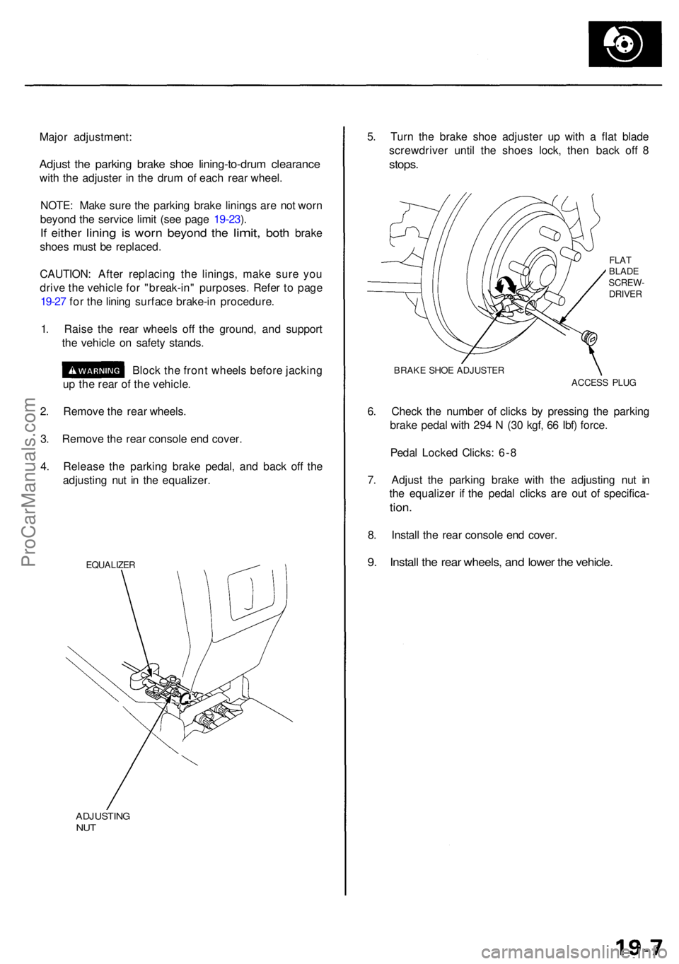
Major adjustment :
Adjust th e parkin g brak e sho e lining-to-dru m clearanc e
with th e adjuste r i n th e dru m o f eac h rea r wheel .
NOTE : Mak e sur e th e parkin g brak e lining s ar e no t wor n
beyon d th e servic e limi t (se e pag e 19-23 ).
If eithe r lining is wor n beyon d the limit , both brak e
shoe s mus t b e replaced .
CAUTION : Afte r replacin g th e linings , mak e sur e yo u
driv e th e vehicl e fo r "break-in " purposes . Refe r t o pag e
19-2 7 fo r th e linin g surfac e brake-i n procedure .
1 . Rais e th e rea r wheel s of f th e ground , an d suppor t
th e vehicl e o n safet y stands .
Bloc k th e fron t wheel s befor e jackin g
u p th e rea r o f th e vehicle .
2 . Remov e th e rea r wheels .
3 . Remov e th e rea r consol e en d cover .
4 . Releas e th e parkin g brak e pedal , an d bac k of f th e
adjustin g nu t i n th e equalizer .
EQUALIZE R
ADJUSTIN GNUT
5. Tur n th e brak e sho e adjuste r u p wit h a fla t blad e
screwdrive r unti l th e shoe s lock , the n bac k of f 8
stops .
FLATBLAD E
SCREW -
DRIVE R
BRAK E SHO E ADJUSTE R
ACCESS PLU G
6. Chec k th e numbe r o f click s b y pressin g th e parkin g
brak e peda l wit h 29 4 N (3 0 kgf , 6 6 Ibf ) force .
Peda l Locke d Clicks : 6- 8
7 . Adjus t th e parkin g brak e wit h th e adjustin g nu t i n
th e equalize r i f th e peda l click s ar e ou t o f specifica -
tion.
8. Instal l th e rea r consol e en d cover .
9. Instal l th e rea r wheels , an d lowe r th e vehicle .
ProCarManuals.com
Page 1061 of 1954
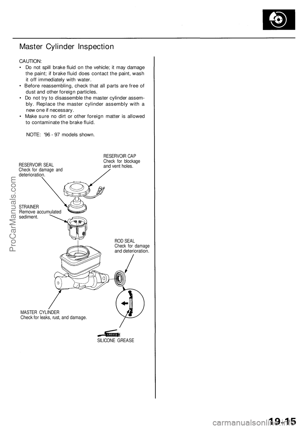
Master Cylinder Inspection
CAUTION:
• Do not spill brake fluid on the vehicle; it may damage
the paint; if brake fluid does contact the paint, wash
it off immediately with water.
• Before reassembling, check that all parts are free of
dust and other foreign particles.
• Do not try to disassemble the master cylinder assem-
bly. Replace the master cylinder assembly with a
new one if necessary.
• Make sure no dirt or other foreign matter is allowed
to contaminate the brake fluid.
NOTE: '96 - 97 models shown.
RESERVOIR SEAL
Check for damage and
deterioration.
RESERVOIR CAP
Check for blockage
and vent holes.
STRAINER
Remove accumulated
sediment.
ROD SEAL
Check for damage
and deterioration.
MASTER CYLINDER
Check for leaks, rust, and damage.
SILICONE GREASEProCarManuals.com
Page 1063 of 1954
Master Cylinder/Brak e Booste r
Pushrod Clearanc e Adjustmen t
(cont'd)
NOTE: I f th e clearanc e betwee n th e gaug e bod y an d
adjustin g nu t i s 0. 2 m m (0.00 8 in) , th e pushrod-to-pisto n
clearance i s 0 mm . However , i f th e clearanc e betwee n
th e gaug e bod y an d adjustin g nu t i s 0 mm , th e pushrod -
to-pisto n clearanc e i s 0. 2 m m (0.00 8 in ) o r more .
Therefor e it mus t b e adjuste d an d rechecked .
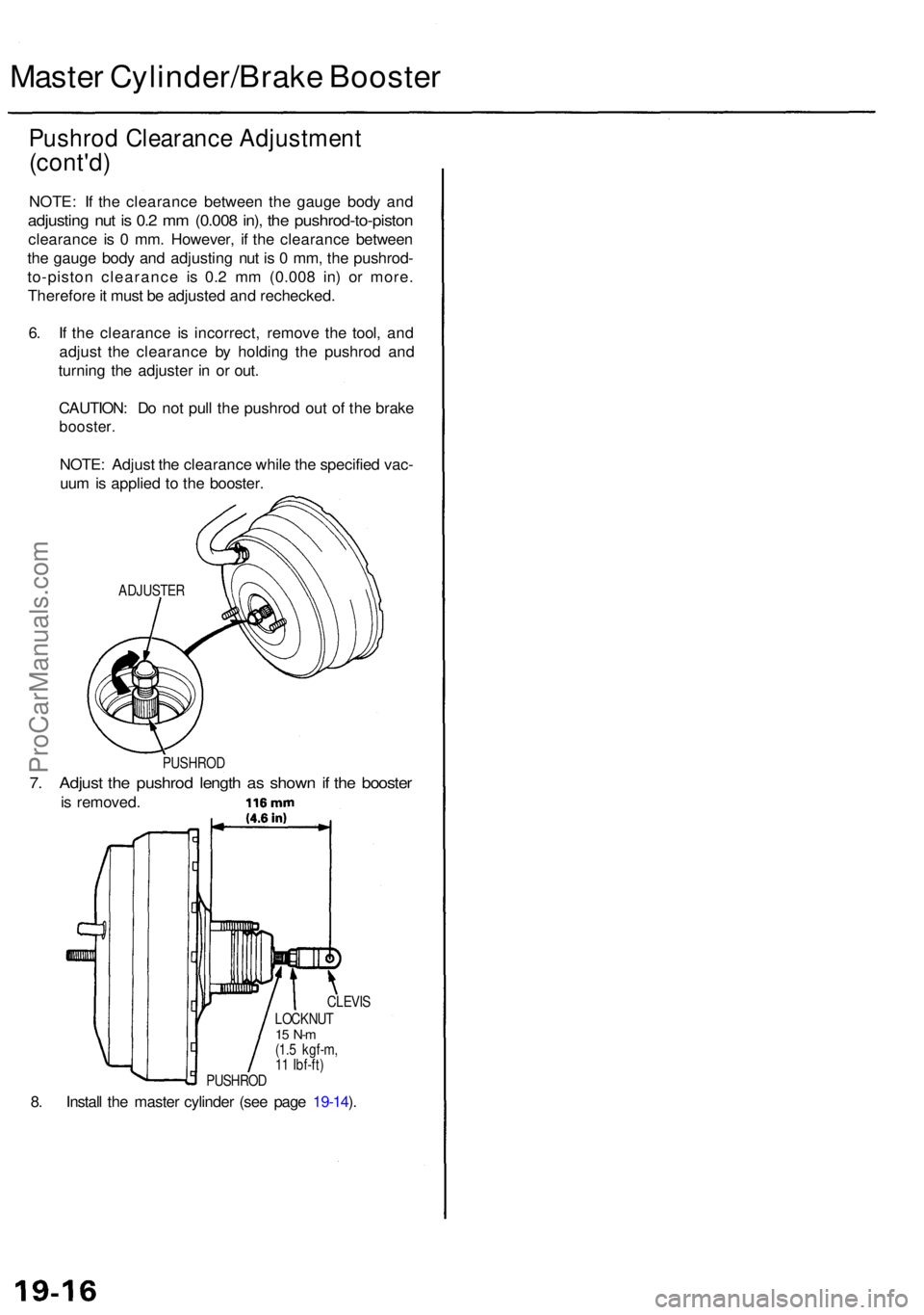
6 . I f th e clearanc e i s incorrect , remov e th e tool , an d
adjus t th e clearanc e b y holding the pushro d an d
turnin g th e adjuste r i n o r out .
CAUTION : D o no t pul l th e pushro d ou t o f th e brak e
booster .
NOTE: Adjus t th e clearanc e whil e th e specifie d vac -
uu m is applie d t o th e booster .
ADJUSTE R
PUSHRO D
7. Adjus t th e pushro d lengt h a s show n if th e booste r
is removed .
8 . Instal l th e maste r cylinde r (se e pag e 19-14 ).
PUSHRO DLOCKNU
T
15 N- m(1.5 kgf-m ,
1 1 Ibf-ft )CLEVI
S
ProCarManuals.com
Page 1065 of 1954
Rear Brake Pads
Inspection and Replacement
Never use an air hose or dry brush to clean brake
assemblies.
Use an OSHA-approved vacuum cleaner to avoid
breathing brake dust.
Block the front wheels before jacking up the rear of
the vehicle.
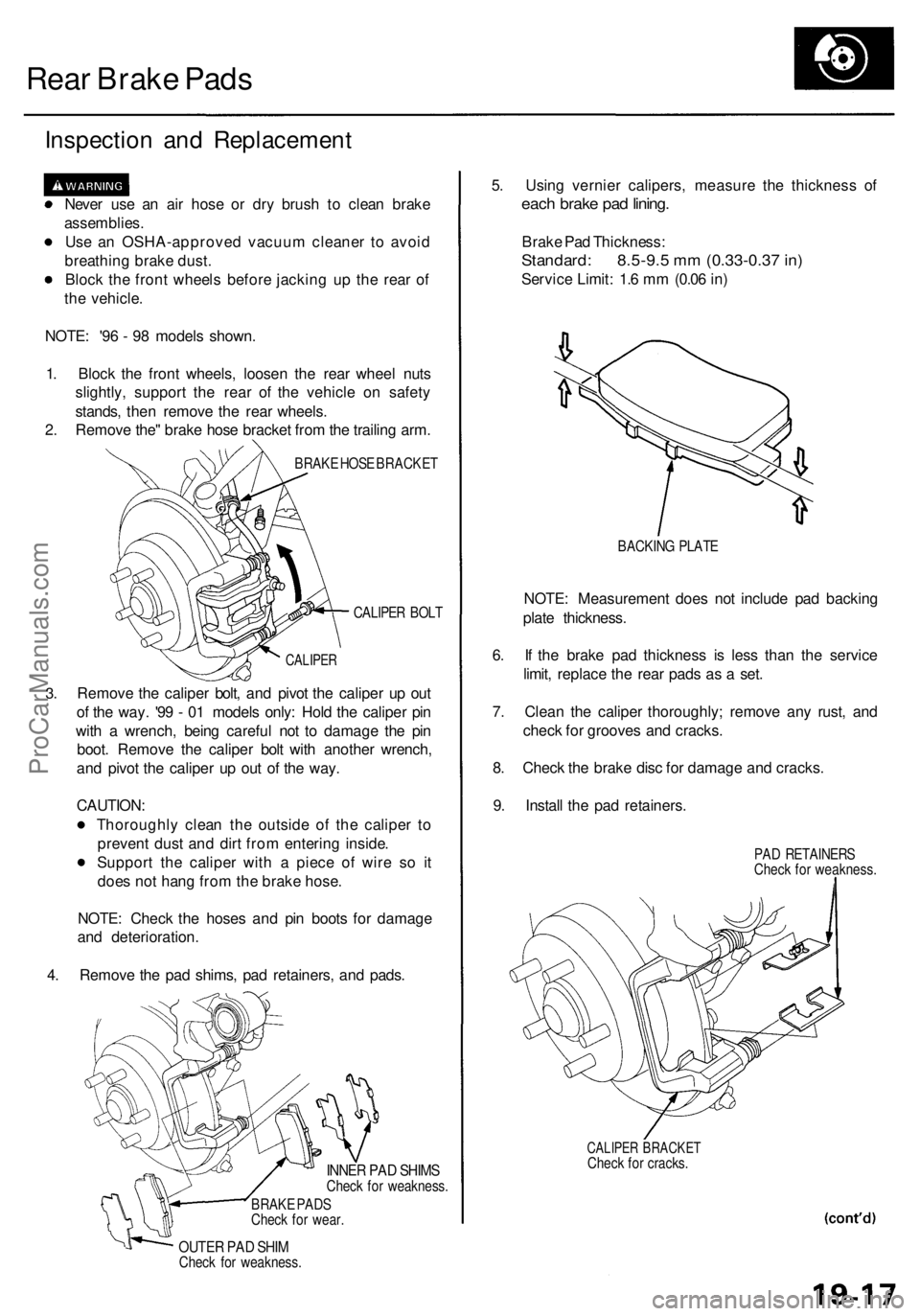
NOTE: '96 - 98 models shown.
1. Block the front wheels, loosen the rear wheel nuts
slightly, support the rear of the vehicle on safety
stands, then remove the rear wheels.
2. Remove the" brake hose bracket from the trailing arm.
BRAKE HOSE BRACKET
CALIPER BOLT
3.
CALIPER
Remove the caliper bolt, and pivot the caliper up out
of the way. '99 - 01 models only: Hold the caliper pin
with a wrench, being careful not to damage the pin
boot. Remove the caliper bolt with another wrench,
and pivot the caliper up out of the way.
CAUTION:
Thoroughly clean the outside of the caliper to
prevent dust and dirt from entering inside.
Support the caliper with a piece of wire so it
does not hang from the brake hose.
NOTE: Check the hoses and pin boots for damage
and deterioration.
4. Remove the pad shims, pad retainers, and pads.
INNER PAD SHIMS
Check for weakness.
BRAKE PADS
Check for wear.
OUTER PAD SHIM
Check for weakness.
5. Using vernier calipers, measure the thickness of
each brake pad lining.
Brake Pad Thickness:
Standard: 8.5-9.5 mm (0.33-0.37 in)
Service Limit: 1.6 mm (0.06 in)
BACKING PLATE
NOTE: Measurement does not include pad backing
plate thickness.
6. If the brake pad thickness is less than the service
limit, replace the rear pads as a set.
7. Clean the caliper thoroughly; remove any rust, and
check for grooves and cracks.
8. Check the brake disc for damage and cracks.
9. Install the pad retainers.
PAD RETAINERS
Check for weakness.
CALIPER BRACKET
Check for cracks.ProCarManuals.com