1996 ACURA RL KA9 lock
[x] Cancel search: lockPage 947 of 1954
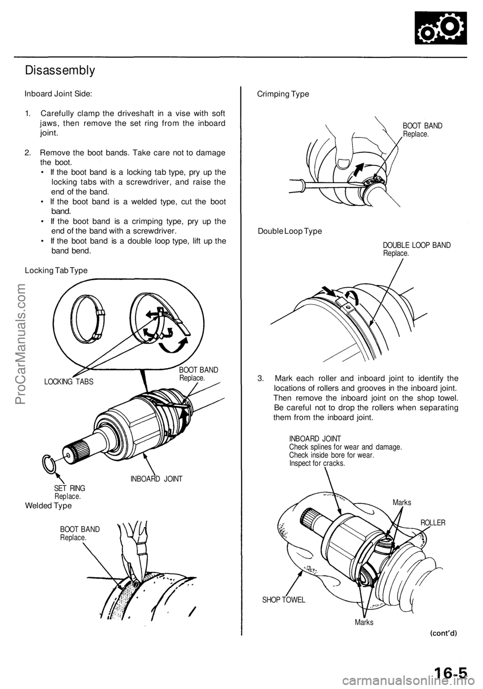
SET RIN GReplace .
Welded Typ e
BOO T BAN DReplace .
INBOARD JOIN T
SHOP TOWE L
Marks
Crimpin g Typ e
BOO T BAN DReplace .
Double Loo p Typ e
DOUBL E LOO P BAN DReplace .
3. Mar k eac h rolle r an d inboar d join t t o identif y th e
location s o f roller s an d groove s in th e inboar d joint .
The n remov e th e inboar d join t o n th e sho p towel .
B e carefu l no t t o dro p th e roller s whe n separatin g
the m fro m th e inboar d joint .
INBOAR D JOIN T
Chec k spline s fo r wea r an d damage .
Chec k insid e bor e fo r wear .
Inspec t fo r cracks .
ROLLER
Marks
Disassembl y
Inboard Join t Side :
1 . Carefull y clam p th e driveshaf t i n a vis e wit h sof t
jaws , the n remov e th e se t rin g fro m th e inboar d
joint.
2. Remov e th e boo t bands . Tak e car e no t t o damag e
th e boot .
• I f th e boo t ban d i s a lockin g ta b type , pr y u p th e
lockin g tab s wit h a screwdriver , an d rais e th e
en d o f th e band .
• I f th e boo t ban d i s a welde d type , cu t th e boo t
band.
• I f th e boo t ban d i s a crimpin g type , pr y u p th e
en d o f th e ban d wit h a screwdriver .
• I f th e boo t ban d i s a doubl e loo p type , lif t u p th e
ban d bend .
Lockin g Ta b Typ e
LOCKIN G TAB S BOO
T BAN D
Replace .
ProCarManuals.com
Page 948 of 1954
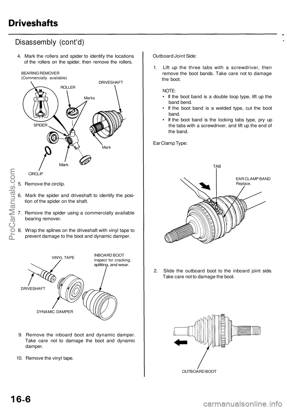
9. Remov e th e inboar d boo t an d dynami c damper .
Tak e car e no t t o damag e th e boo t an d dynami c
damper .
10 . Remov e th e viny l tape .
DYNAMI C DAMPE R INBOAR
D BOO T
Inspec t fo r cracking ,
splitting, an d wear .
VINY L TAP E
DRIVESHAF T
5. Remov e th e circlip .
6 . Mar k th e spide r an d driveshaf t t o identif y th e posi -
tio n o f th e spide r o n th e shaft .
7 . Remov e th e spide r usin g a commerciall y availabl e
bearin g remover .
8 . Wra p th e spline s o n th e driveshaf t wit h viny l tap e t o
preven t damag e to th e boo t an d dynami c damper .
CIRCLIP
Mark
Mar k
SPIDE R
Disassembl y (cont'd )
4. Mar k th e roller s an d spide r t o identif y th e location s
o f th e roller s o n th e spider , the n remov e th e rollers .
BEARIN G REMOVE R
(Commerciall y available )
ROLLER
Marks
DRIVESHAF T
Outboard Join t Side :
1 . Lif t u p th e thre e tab s wit h a screwdriver , the n
remov e th e boo t bands . Tak e car e no t t o damag e
th e boot .
NOTE :
• I f th e boo t ban d i s a doubl e loo p type , lif t u p th e
ban d bend .
• I f th e boo t ban d i s a welde d type , cu t th e boo t
band .
• I f th e boo t ban d i s th e lockin g tab s type , pr y u p
th e tab s wit h a screwdriver , an d lif t u p th e en d o f
th e band .
Ea r Clam p Type :
EAR CLAM P BAN DReplace .
TAB
2. Slid e th e outboar d boo t t o th e inboar d join t side .
Tak e car e no t t o damag e th e boot .
OUTBOAR D BOO T
ProCarManuals.com
Page 958 of 1954
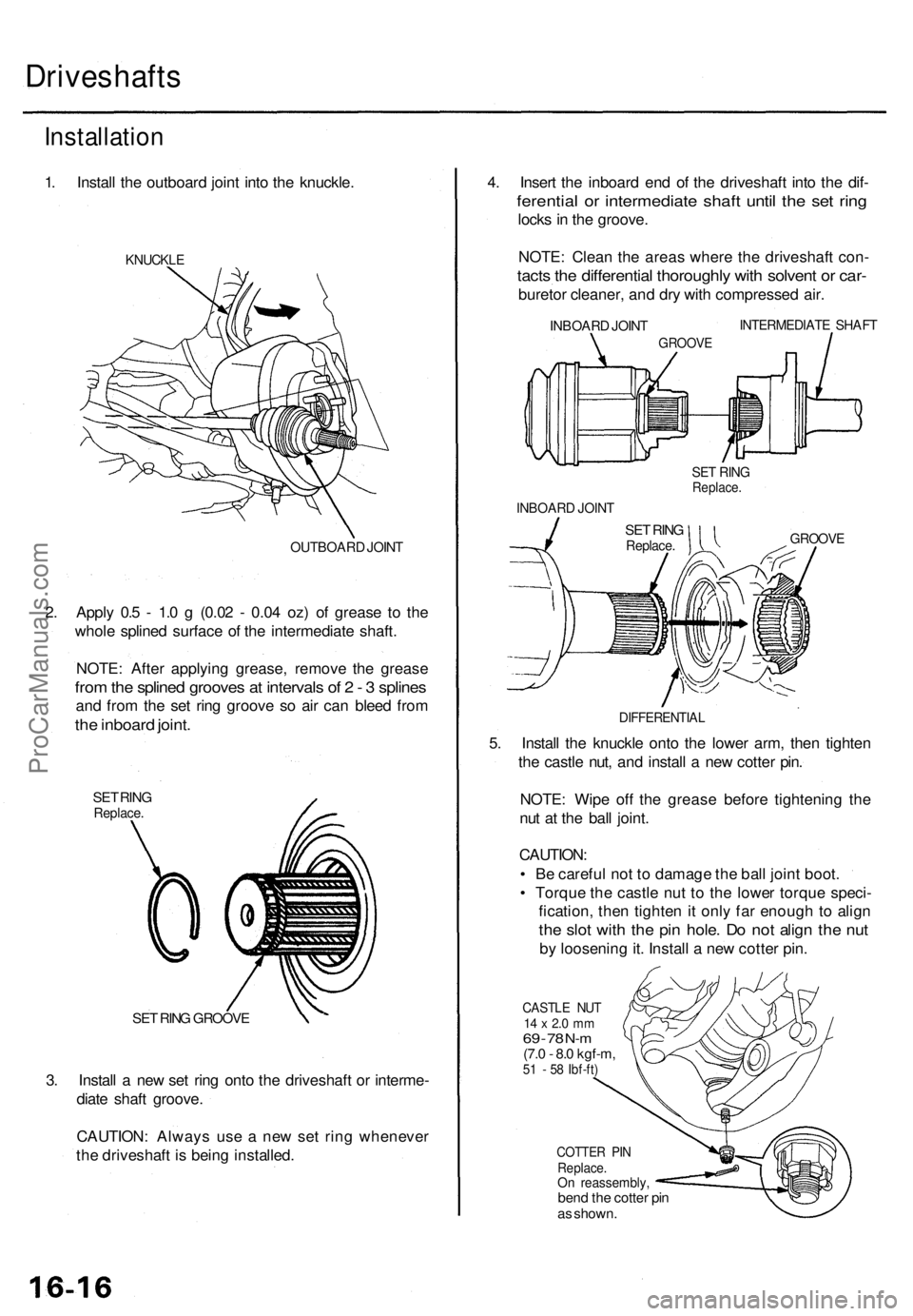
3. Instal l a ne w se t rin g ont o th e driveshaf t o r interme -
diat e shaf t groove .
CAUTION : Alway s us e a ne w se t rin g wheneve r
th e driveshaf t i s bein g installed .
SET RIN G GROOV E
Driveshaft s
Installation
1. Instal l th e outboar d join t int o th e knuckle .
KNUCKL E
4. Inser t th e inboar d en d o f th e driveshaf t int o th e dif -
ferentia l o r intermediat e shaf t unti l th e se t rin g
lock s in th e groove .
NOTE : Clea n th e area s wher e th e driveshaf t con -
tacts th e differentia l thoroughl y wit h solven t o r car -
bureto r cleaner , an d dr y wit h compresse d air .
INTERMEDIAT E SHAF T
GROOV E
INBOAR D JOIN T
SET RIN GReplace .
INBOAR D JOIN T
SET RIN GReplace .GROOV E
DIFFERENTIA L
5. Instal l th e knuckl e ont o th e lowe r arm , the n tighte n
th e castl e nut , an d instal l a ne w cotte r pin .
NOTE : Wip e of f th e greas e befor e tightenin g th e
nu t a t th e bal l joint .
CAUTION :
• B e carefu l no t t o damag e th e bal l join t boot .
• Torqu e th e castl e nu t t o th e lowe r torqu e speci -
fication , the n tighte n it onl y fa r enoug h t o alig n
the slo t wit h th e pi n hole . D o no t alig n th e nu t
by loosenin g it . Instal l a ne w cotte r pin .
CASTL E NU T14 x 2. 0 m m69 - 7 8 N- m(7. 0 - 8. 0 kgf-m ,51 - 5 8 Ibf-ft )
COTTE R PI NReplace .On reassembly ,bend th e cotte r pi n
a s shown .
2. Appl y 0. 5 - 1. 0 g (0.0 2 - 0.0 4 oz ) o f greas e t o th e
whol e spline d surfac e o f th e intermediat e shaft .
NOTE : Afte r applyin g grease , remove the greas e
from th e spline d groove s a t interval s o f 2 - 3 spline s
and fro m th e se t rin g groov e s o ai r ca n blee d fro m
the inboar d joint .
SET RIN GReplace .
OUTBOAR D JOIN T
ProCarManuals.com
Page 959 of 1954
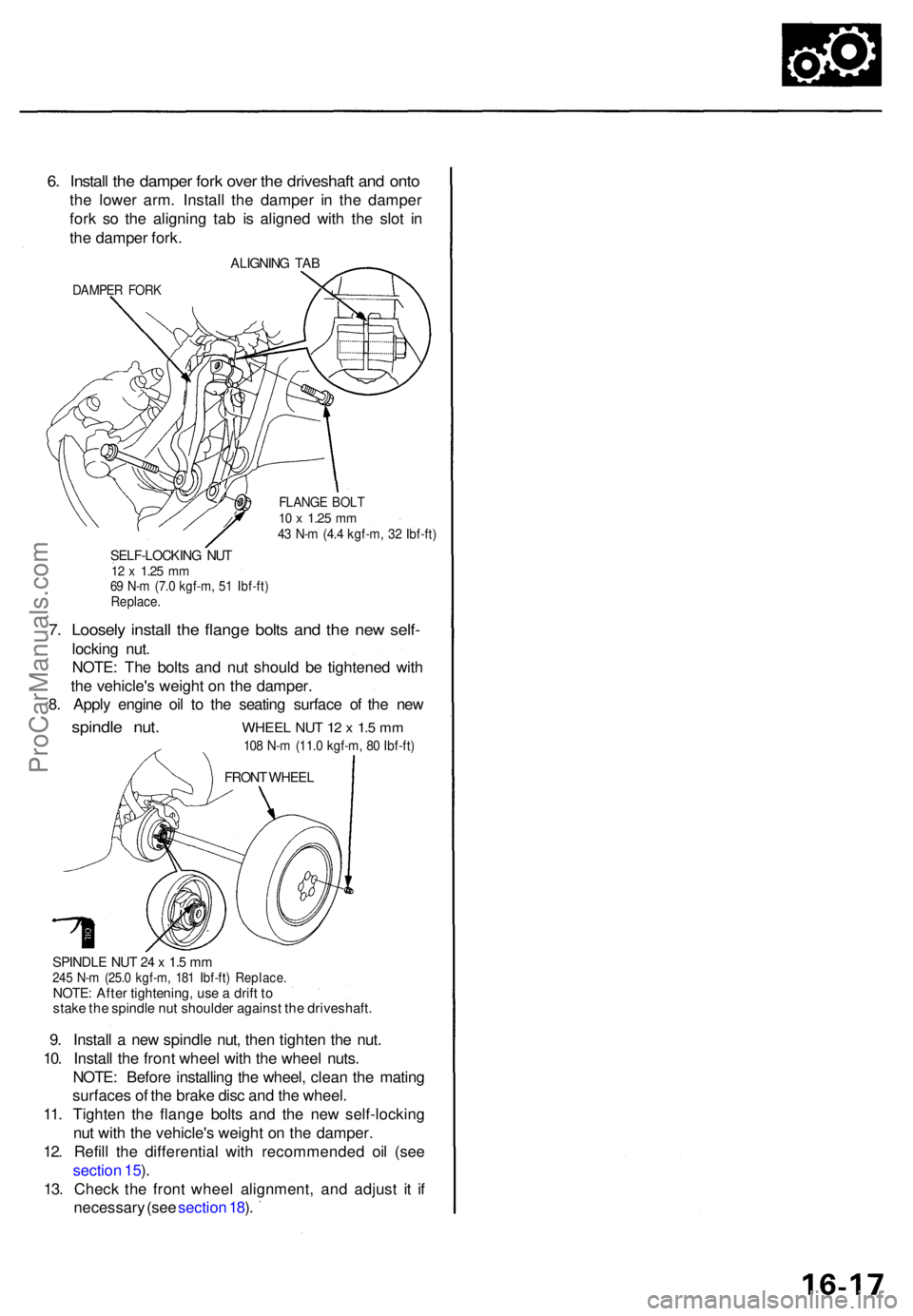
6. Instal l th e dampe r for k ove r th e driveshaf t an d ont o
the lowe r arm . Instal l th e dampe r i n th e dampe r
for k s o th e alignin g ta b i s aligne d wit h th e slo t i n
th e dampe r fork .
ALIGNIN G TAB
DAMPE R FOR K
FLANG E BOL T10 x 1.2 5 mm43 N- m (4. 4 kgf-m , 3 2 Ibf-ft )
SELF-LOCKIN G NU T12 x 1.2 5 mm69 N- m (7. 0 kgf-m , 5 1 Ibf-ft )Replace .
7. Loosel y instal l th e flang e bolt s an d th e ne w self -
lockin g nut .
NOTE : Th e bolt s an d nu t shoul d b e tightene d wit h
th e vehicle' s weigh t o n th e damper .
8 . Appl y engin e oi l t o th e seatin g surfac e o f th e ne w
spindl e nut . WHEE L NU T 1 2 x 1. 5 m m
108 N- m (11. 0 kgf-m , 8 0 Ibf-ft )
SPINDL E NU T 2 4 x 1. 5 m m245 N- m (25. 0 kgf-m , 18 1 Ibf-ft ) Replace .NOTE: Afte r tightening , us e a drif t t o
stak e th e spindl e nu t shoulde r agains t th e driveshaft .
9. Instal l a ne w spindl e nut , the n tighte n th e nut .
10 . Instal l th e fron t whee l wit h th e whee l nuts .
NOTE : Befor e installin g th e wheel , clea n th e matin g
surface s o f th e brak e dis c an d th e wheel .
11 . Tighten the flang e bolt s an d th e ne w self-lockin g
nu t wit h th e vehicle' s weigh t o n th e damper .
12 . Refil l th e differentia l with recommende d oi l (se e
sectio n 15 ).
13 . Chec k th e fron t whee l alignment , an d adjus t i t i f
necessar y (se e sectio n 18 ).
FRON T WHEE L
ProCarManuals.com
Page 971 of 1954
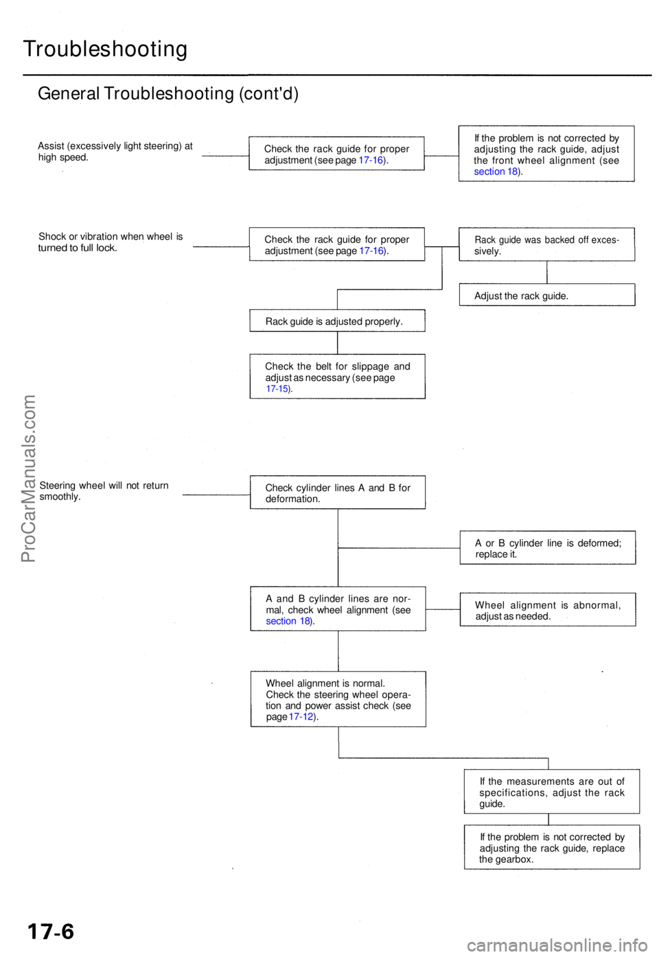
Troubleshooting
General Troubleshootin g (cont'd )
Assist (excessivel y ligh t steering ) a t
hig h speed .
Shoc k o r vibratio n whe n whee l i s
turne d to ful l lock .
Steerin g whee l wil l no t retur n
smoothly .
If th e proble m is no t correcte d b y
adjustin g th e rac k guide , replace
th e gearbox .
I
f th e measurement s ar e ou t o f
specifications , adjus t th e rac k
guide .
Whee
l alignmen t i s normal .
Chec k th e steerin g whee l opera -
tio n an d powe r assis t chec k (se e
pag e 17-12 ).
A
an d B cylinde r line s ar e nor -
mal , chec k whee l alignmen t (se e
sectio n 18 ). Whee
l alignmen t i s abnormal ,
adjus t a s needed .
A
o r B cylinde r lin e i s deformed ;
replac e it .
Chec
k cylinde r line s A an d B fo r
deformation .
Chec
k th e rac k guid e fo r prope r
adjustmen t (se e pag e 17-16 ).
Chec k th e rac k guid e fo r prope r
adjustmen t (se e pag e 17-16 ).
Rac k guid e is adjuste d properly .
Chec k th e bel t fo r slippag e an d
adjus t a s necessar y (se e pag e
17-15 ).
If th e proble m is no t correcte d b y
adjustin g th e rac k guide , adjus t
th e fron t whee l alignmen t (se e
sectio n 18 ).
Rac k guid e wa s backe d of f exces -sively.
Adjus t th e rac k guide .
ProCarManuals.com
Page 977 of 1954

Inspection an d Adjustmen t
Steering Operatio n
Place th e fron t wheel s i n th e straigh t ahea d position ,
an d measur e th e distanc e th e steerin g whee l ca n b e
turne d withou t movin g th e fron t wheels .
ROTATIONA L PLAY : 0 - 1 0 m m (0 - 0.3 9 in )
If th e pla y exceed s th e servic e limit, perfor m rack guid e
adjustmen t (se e pag e 17-16 ).
I f th e pla y i s stil l excessiv e afte r rac k guid e adjustment ,
inspec t th e steerin g linkag e an d gearbo x (se e pag e
17-14 ).
Powe r Assis t Chec k wit h Vehicl e
Parked
1. Chec k th e powe r steerin g flui d leve l (se e pag e 17-16 )
an d pum p bel t tensio n (se e pag e 17-15 ).
2 . Star t th e engine , allo w it t o idle , an d tur n th e steer -
in g whee l fro m lock-to-loc k severa l time s t o war m
up th e fluid .
3. Attac h a sprin g scal e to th e steerin g wheel . Wit h th e
engin e idlin g an d th e vehicl e o n a clean , dr y floor ,
pul l th e scal e a s shown . Rotat e th e steerin g whee l
mor e tha n 9 0 degre e angl e b y pullin g th e sprin g
scale . Rea d th e figur e o n th e sprin g scal e whil e th e
steerin g whee l i s in motion .
4 . Th e scal e shoul d rea d n o mor e the n 2 5 N (2. 6 kgf ,
5. 7 Ibf) . I f i t read s more , g o o n to ste p 5 .
5 . Sto p th e engine . Disconnec t th e senso r inle t hos e
fro m th e powe r steerin g spee d sensor , an d plu g th e
hos e an d th e senso r fittin g a s shown .
6 . Star t th e engine , an d le t i t idle .
• I f th e readin g i s stil l mor e tha n 2 5 N (2. 6 kgf , 5. 7
Ibf ) th e powe r steerin g spee d senso r i s OK .
Proble m is i n th e pum p o r valv e bod y uni t (se e
Genera l Troubleshooting) .
• I f th e readin g is no w 2 5 N (2. 6 kgf , 5. 7 Ibf ) o r less ,
powe r steerin g spee d senso r leak s internally .
Replac e th e senso r (se e pag e 17-13 ).
ProCarManuals.com
Page 978 of 1954

Assist Chec k a t Roa d Spee d
Assist (excessivel y ligh t steering ) a t hig h speed :
1 . Chec k th e powe r steerin g flui d leve l (se e pag e 17-16 ),
an d pum p bel t tensio n (se e pag e 17-15 ).
2 . Star t th e engine , allo w it t o idle , an d tur n th e steerin g
whee l fro m lock-to-loc k severa l time s t o war m u p th e
fluid .
3. Sto p th e engine . T o simulat e speed s abov e 6 2 mp h
(10 0 km/h) , disconnec t th e hose s fro m th e powe r
steerin g spee d sensor , an d connec t the m to th e
bypas s tub e joint . Plu g th e en d o f th e bypas s tub e
joint .
Powe r Steerin g Spee d Senso r
Replacemen t
1. Disconnec t th e VS S connecto r fro m th e powe r steer -
in g spee d sensor .
2 . Remov e th e senso r mountin g bolt , the n remov e th e
powe r steerin g spee d senso r fro m th e differentia l
housing .
3 . Disconnec t th e senso r inle t an d outle t hoses , an d
plu g th e hos e fittings .
4 . Installatio n is th e revers e o f th e remova l procedure .
5 . Afte r installin g a ne w sensor , tur n th e steerin g
whee l lock-to-loc k wit h th e engine idling t o blee d ai r
fro m th e system .
6 . Chec k th e reservoir , an d ad d flui d if necessary .
BYPASS TUB E JOIN T07406-001010 1(Included wit h07406-0010001 )
4. Attac h a sprin g scal e to th e steerin g wheel .
Star t th e engine ; wit h th e engin e idlin g an d th e vehi -
cl e o n a clean , dr y floor , pul l th e scal e a s shown .
Rotat e th e steerin g whee l mor e tha n 9 0 degree s b y
pullin g th e sprin g scale . Rea d th e figur e o n th e
sprin g scal e whil e th e steerin g whee l i s i n motion .
• I f th e scal e read s mor e tha n 2 5 N (2. 6 kgf , 5. 7
Ibf) , th e valv e bod y uni t i s OK .
Th e powe r steerin g spee d senso r abnormal .
Replac e th e sensor , an d chec k b y roadtesting .
• I f th e readin g is no w 2 5 N (2. 6 kgf , 5. 7 Ibf ) o r less ,
proble m is i n th e valv e bod y uni t o r pum p (se e
Genera l Troubleshooting) .
ProCarManuals.com
Page 980 of 1954
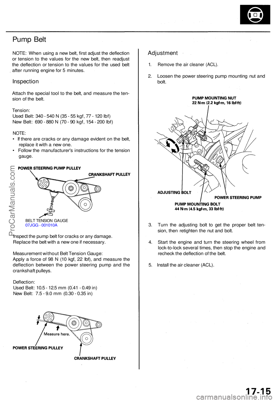
BELT TENSIO N GAUG E07JGG - 001010 A
Inspect th e pum p bel t fo r crack s o r an y damage .
Replac e th e bel t wit h a ne w on e if necessary .
Measuremen t withou t Bel t Tensio n Gauge :
Appl y a forc e o f 9 8 N (1 0 kgf , 2 2 Ibf) , an d measur e th e
deflectio n betwee n th e powe r steerin g pum p an d th e
crankshaf t pulleys .
Deflection :
Used Belt : 10. 5 - 12. 5 m m (0.4 1 - 0.4 9 in )
Ne w Belt : 7. 5 - 9. 0 m m (0.3 0 - 0.3 5 in ) 3
. Tur n th e adjustin g bol t t o ge t th e prope r bel t ten -
sion , the n retighte n th e nu t an d bolt .
4 . Star t th e engin e an d tur n th e steerin g whee l fro m
lock-to-loc k severa l times , the n sto p th e engin e an d
rechec k th e deflectio n o f th e belt .
5 . Instal l th e ai r cleane r (ACL) .
Adjustmen t
1. Remov e th e ai r cleane r (ACL) .
2. Loose n th e powe r steerin g pum p mountin g nu t an d
bolt .
Pum p Bel t
NOTE : Whe n usin g a ne w belt , firs t adjus t th e deflectio n
o r tensio n t o th e value s fo r th e ne w belt , the n readjus t
th e deflectio n o r tensio n t o th e value s fo r th e use d bel t
afte r runnin g engin e fo r 5 minutes .
Inspectio n
Attach th e specia l too l t o th e belt , an d measur e th e ten -
sio n o f th e belt .
Tension :
Used Belt : 34 0 - 54 0 N (3 5 - 5 5 kgf , 7 7 - 12 0 Ibf )
Ne w Belt : 69 0 - 88 0 N (7 0 - 9 0 kgf , 15 4 - 20 0 Ibf )
NOTE :
• I f ther e ar e crack s o r an y damag e eviden t o n th e belt ,
replac e it wit h a ne w one .
• Follo w th e manufacturer' s instruction s fo r th e tensio n
gauge.
ProCarManuals.com