1996 ACURA RL KA9 lock
[x] Cancel search: lockPage 981 of 1954

2. Tighte n th e rac k guid e scre w to 2 5 N- m (2. 5 kgf-m ,
18lbf-ft) , the n loose n it .
3 . Retighte n th e rac k guid e scre w to 5. 9 N- m (0. 6 kgfm ,
4 Ibf-ft) , the n bac k it of f t o specifie d angle .
Specifie d Retur n Angle : 1 5 ± 5°
4 . Tighte n th e locknu t whil e holdin g th e rac k guid e
screw .
5 . Chec k fo r tigh t o r loos e steerin g throug h th e com -
plet e turnin g travel .
6 . Perfor m th e followin g inspection s (se e pag e 17-12 ).
• Steerin g operation .
• Powe r assis t wit h vehicl e parked . 2
. Connec t a hos e o f correc t diamete r t o th e discon -
necte d retur n hose , an d pu t th e hos e en d i n a suit -
abl e container .
CAUTION : Tak e car e no t t o spil l th e flui d o n th e
bod y an d parts . Wip e of f an y spille d flui d a t once .
3 . Star t th e engine , le t i t ru n a t idle , an d tur n th e steer -
in g whee l fro m lock-to-loc k severa l times . Whe n
flui d stop s runnin g ou t of the hose , shu t of f th e
engine . Discar d th e fluid .
4 . Reinstal l th e retur n hos e o n th e reservoir .
5 . Fil l th e reservoi r t o th e uppe r leve l line .
6 . Star t th e engin e an d ru n i t a t fas t idle , the n tur n th e
steerin g fro m lock-to-loc k severa l time s t o blee d ai r
fro m th e system .
7 . Rechec k th e flui d leve l an d ad d mor e if necessary .
CAUTION : D o no t fil l th e reservoi r beyon d th e
uppe r leve l line .
Inspectio n an d Adjustmen t
Rack Guid e Adjustmen t
NOTE: Perfor m rac k guid e adjustmen t wit h th e wheel s
i n th e straigh t ahea d position .
1 . Loose n th e rac k guid e scre w locknu t wit h th e spe -
cial tool .
'96 - 9 8 models :
Loose n th e rac k guid e screw .
'9 9 - 0 1 models :
Remov e th e rac k guid e screw . Remov e th e ol d
sealan t fro m th e rac k guid e scre w threade d section ,
an d appl y ne w sealan t t o th e al l aroun d threads .
Loosel y instal l th e rac k guid e scre w o n th e steerin g
gearbox .
Fluid Replacemen t
Check th e reservoi r a t regula r intervals , an d ad d th e rec -
ommende d flui d a s necessary .
CAUTION : Alway s us e Genuin e Hond a Powe r Steerin g
Fluid- V o r S . Usin g an y othe r typ e o f powe r steerin g
flui d o r automati c transmissio n flui d ca n caus e
increase d wea r an d poo r steerin g in col d weather .
ProCarManuals.com
Page 982 of 1954
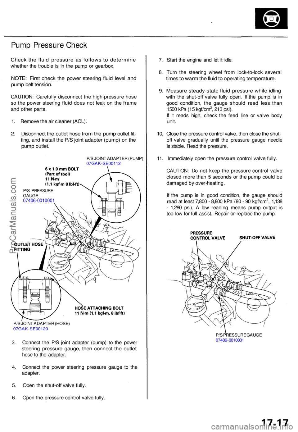
Pump Pressur e Chec k
Check th e flui d pressur e a s follow s t o determin e
whether th e troubl e i s i n th e pum p o r gearbox .
NOTE: Firs t chec k th e powe r steerin g flui d leve l an d
pum p bel t tension .
CAUTION : Carefull y disconnec t th e high-pressur e hos e
s o th e powe r steerin g flui d doe s no t lea k o n th e fram e
an d othe r parts .
1 . Remov e th e ai r cleane r (ACL) .
2. Disconnec t th e outle t hos e fro m th e pum p outle t fit -
ting , an d instal l th e P/ S join t adapte r (pump ) o n th e
pum p outlet .
P/S JOIN T ADAPTE R (PUMP )
07GAK-SE0011 2
P/S PRESSUR EGAUGE07406-0010001
P/S JOIN T ADAPTE R (HOSE )07GAK-SE0012 0
3. Connec t th e P/ S join t adapte r (pump ) t o th e powe r
steerin g pressur e gauge , the n connec t th e outle t
hose t o th e adapter .
4 . Connec t th e powe r steerin g pressur e gaug e t o th e
adapter .
5 . Ope n th e shut-of f valv e fully .
6 . Ope n th e pressur e contro l valv e fully .
P/S PRESSUR E GAUG E
0740 6-001000 1
7. Star t th e engin e an d le t i t idle .
8 . Tur n th e steerin g whee l fro m lock-to-loc k severa l
times to war m th e flui d to operatin g temperature .
9. Measur e steady-stat e flui d pressur e whil e idlin g
with th e shut-of f valv e full y open . I f th e pum p i s i n
goo d condition , th e gaug e shoul d rea d les s tha n
150 0 kP a (1 5 kgf/cm
2, 21 3 psi) .
I f i t read s high , chec k th e fee d lin e o r valv e bod y
unit.
10. Clos e th e pressur e contro l valve , the n clos e th e shut -
off valv e graduall y unti l th e pressur e gaug e needl e
i s stable . Rea d th e pressure .
11 . Immediatel y ope n th e pressur e contro l valv e fully .
CAUTION : D o no t kee p th e pressur e contro l valv e
close d mor e tha n 5 second s o r th e pum p coul d b e
damage d b y over-heating .
I f th e pum p i s i n goo d condition , th e gaug e shoul d
rea d a t leas t 7,80 0 - 8,80 0 kP a (8 0 - 9 0 kgf/cm
2, 1,13 8
- 1,28 0 psi) . A lo w readin g mean s pum p outpu t i s
to o lo w fo r ful l assist . Repai r o r replac e th e pump .
ProCarManuals.com
Page 983 of 1954
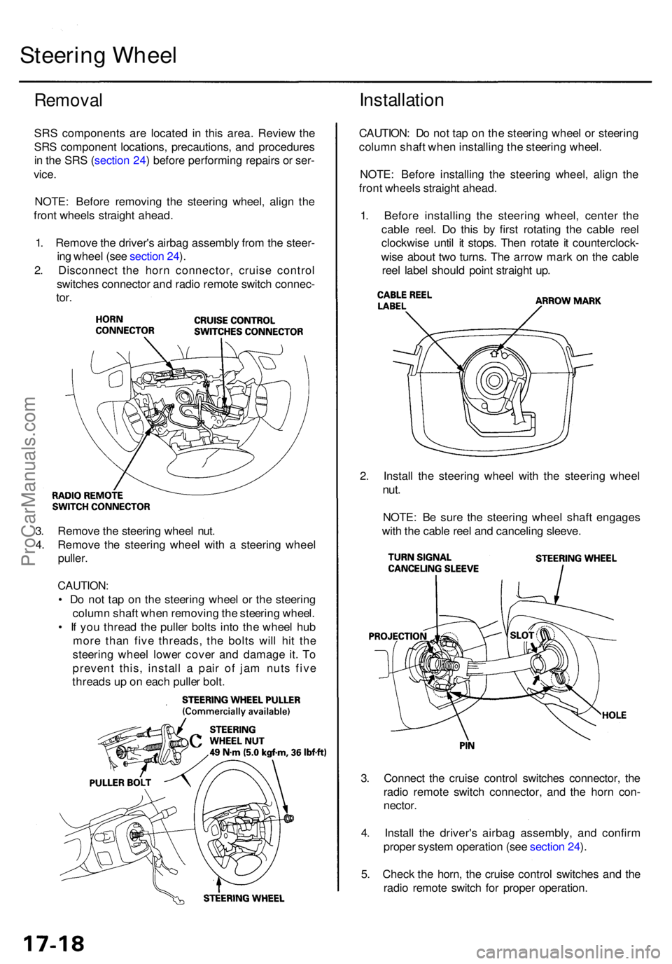
3. Connec t th e cruis e contro l switche s connector , th e
radi o remot e switc h connector , an d th e hor n con -
nector .
4 . Instal l th e driver' s airba g assembly , an d confir m
prope r syste m operatio n (se e sectio n 24 ).
5 . Chec k th e horn , th e cruis e contro l switche s an d th e
radi o remot e switc h fo r prope r operation .
3
. Remov e th e steerin g whee l nut .
4 . Remov e th e steerin g whee l wit h a steerin g whee l
puller .
CAUTION :
• D o no t ta p o n th e steerin g whee l o r th e steerin g
colum n shaf t whe n removin g th e steerin g wheel .
• I f yo u threa d th e pulle r bolt s int o th e whee l hu b
mor e tha n fiv e threads , th e bolt s wil l hi t th e
steerin g whee l lowe r cove r an d damag e it . T o
preven t this , instal l a pai r o f ja m nut s fiv e
thread s u p o n eac h pulle r bolt . 2
. Instal l th e steerin g whee l wit h th e steerin g whee l
nut.
NOTE : B e sur e th e steerin g whee l shaf t engage s
wit h th e cabl e ree l an d cancelin g sleeve .
Remova l
SRS component s ar e locate d i n thi s area . Revie w th e
SR S componen t locations , precautions , an d procedure s
i n th e SR S (sectio n 24 ) befor e performin g repair s o r ser -
vice .
NOTE : Befor e removin g th e steerin g wheel , alig n th e
fron t wheel s straigh t ahead .
1 . Remov e th e driver' s airba g assembl y fro m th e steer -
in g whee l (se e sectio n 24 ).
2 . Disconnec t th e hor n connector , cruis e contro l
switche s connecto r an d radi o remot e switc h connec -
tor.
Installatio n
CAUTION : D o no t ta p o n th e steerin g whee l o r steerin g
colum n shaf t whe n installin g th e steerin g wheel .
NOTE : Befor e installin g th e steerin g wheel , alig n th e
fron t wheel s straigh t ahead .
1 . Befor e installin g th e steerin g wheel , cente r th e
cabl e reel . D o thi s b y firs t rotatin g th e cabl e ree l
clockwis e unti l i t stops . The n rotat e i t counterclock -
wis e abou t tw o turns . Th e arro w mar k o n th e cabl e
ree l labe l shoul d poin t straigh t up .
Steerin g Whee l
ProCarManuals.com
Page 1002 of 1954
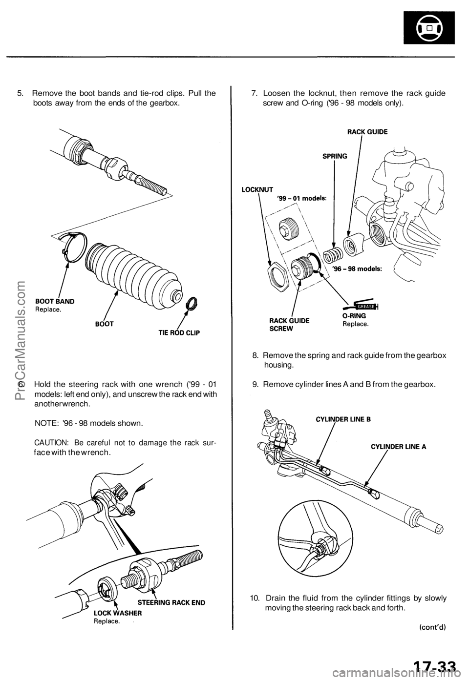
5. Remove the boot bands and tie-rod clips. Pull the
boots away from the ends of the gearbox.
6. Hold the steering rack with one wrench ('99 - 01
models: left end only), and unscrew the rack end with
another wrench.
NOTE: '96 - 98 models shown.
CAUTION: Be careful not to damage the rack sur-
face with the wrench.
7. Loosen the locknut, then remove the rack guide
screw and O-ring ('96 - 98 models only).
8. Remove the spring and rack guide from the gearbox
housing.
9. Remove cylinder lines A and B from the gearbox.
10. Drain the fluid from the cylinder fittings by slowly
moving the steering rack back and forth.ProCarManuals.com
Page 1017 of 1954
Reassembly (cont'd )
d. Determin e th e require d thicknes s o f th e 4 4 m m
shim s b y subtractin g th e clearanc e obtaine d i n th e
ste p - "C " fro m th e tota l thicknes s o f th e fou r shims .
(Tota l thicknes s o f th e fou r shims ) - (Clearance ) =
Require d thicknes s o f th e shim s
NOTE : Selec t th e shim s s o tha t th e tota l thicknes s
i s clos e to , bu t les s tha n th e require d thickness .
Example:
Measuremen t i s 0.2 8 m m (0.01 1 in) :
0.0 7 - 0.2 8 = 0.4 2 m m (0.02 8 - 0.01 1 = 0.01 7 in )
Th e selecte d shim s shoul d b e 0.2 5 m m (0.01 0 in ) an d
0.1 5 m m (0.00 6 in ) i n thickness .
I f th e require d shi m thicknes s i s 0.1 0 m m o r less , n o
shim s ar e necessary .
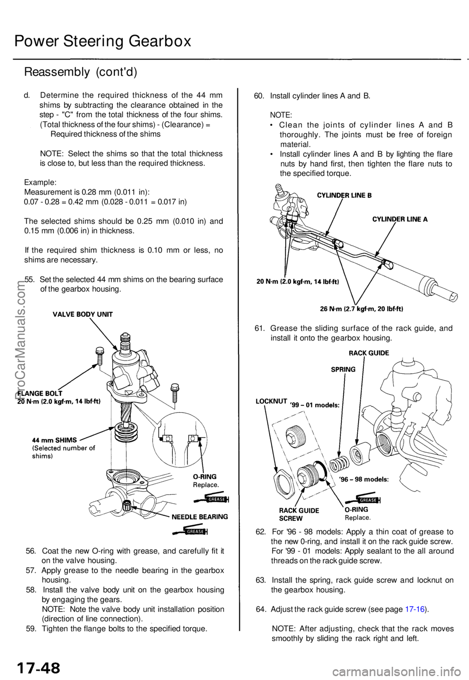
55 . Se t th e selecte d 4 4 m m shim s o n th e bearin g surfac e
o f th e gearbo x housing . 60
. Instal l cylinde r line s A an d B .
NOTE :
• Clea n th e joint s o f cylinde r line s A an d B
thoroughly . Th e joint s mus t b e fre e o f foreig n
material .
• Instal l cylinde r line s A an d B by lightin g th e flar e
nut s b y han d first , the n tighte n th e flar e nut s t o
th e specifie d torque .
Power Steerin g Gearbo x
61. Greas e th e slidin g surfac e of the rac k guide , an d
instal l i t ont o th e gearbo x housing .
62 . Fo r '9 6 - 9 8 models : Appl y a thi n coa t o f greas e t o
th e ne w 0-ring , an d instal l i t o n th e rac k guid e screw .
Fo r '9 9 - 0 1 models : Appl y sealan t t o th e al l aroun d
thread s o n th e rac k guid e screw .
63 . Instal l th e spring , rac k guid e scre w an d locknu t o n
th e gearbo x housing .
64 . Adjus t th e rac k guid e scre w (se e pag e 17-16 ).
NOTE : Afte r adjusting , chec k tha t th e rac k move s
smoothl y b y slidin g th e rac k righ t an d left .
56
. Coa t th e ne w O-rin g wit h grease , an d carefull y fi t i t
o n th e valv e housing .
57 . Appl y greas e t o th e needl e bearin g i n th e gearbo x
housing .
58 . Instal l th e valv e bod y uni t o n th e gearbo x housin g
b y engagin g th e gears.
NOTE : Not e th e valv e bod y uni t installatio n positio n
(directio n o f lin e connection) .
59 . Tighte n th e flang e bolt s t o th e specifie d torque .
ProCarManuals.com
Page 1018 of 1954
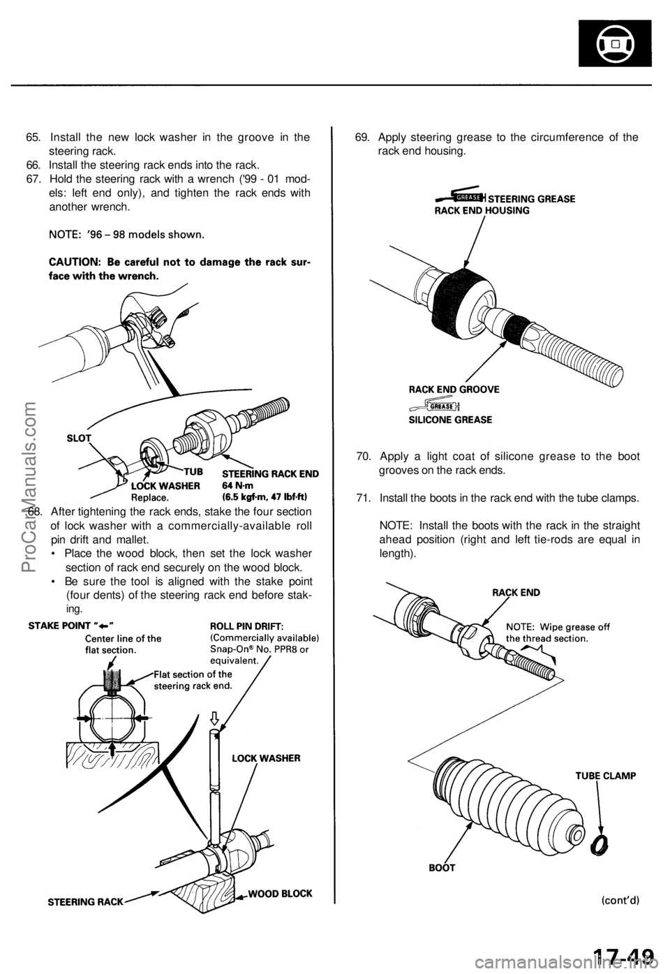
65. Install the new lock washer in the groove in the
steering rack.
66. Install the steering rack ends into the rack.
67. Hold the steering rack with a wrench ('99 - 01 mod-
els: left end only), and tighten the rack ends with
another wrench.
69. Apply steering grease to the circumference of the
rack end housing.
70. Apply a light coat of silicone grease to the boot
grooves on the rack ends.
71. Install the boots in the rack end with the tube clamps.
NOTE: Install the boots with the rack in the straight
ahead position (right and left tie-rods are equal in
length).
68. After tightening the rack ends, stake the four section
of lock washer with a commercially-available roll
pin drift and mallet.
• Place the wood block, then set the lock washer
section of rack end securely on the wood block.
• Be sure the tool is aligned with the stake point
(four dents) of the steering rack end before stak-
ing.ProCarManuals.com
Page 1019 of 1954
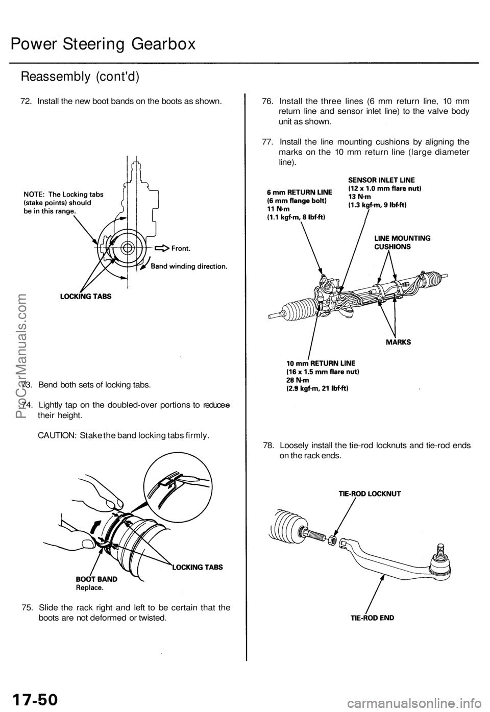
75. Slid e th e rac k righ t an d lef t t o b e certai n tha t th e
boot s ar e no t deforme d o r twisted . 78
. Loosel y instal l th e tie-ro d locknut s an d tie-ro d end s
o n th e rac k ends .
73
. Ben d bot h set s o f lockin g tabs .
74 . Lightl y ta p o n th e doubled-ove r portion s t o reduc e
thei r height .
CAUTION : Stak e th e ban d lockin g tab s firmly . 76
. Instal l th e thre e line s ( 6 m m retur n line , 1 0 m m
retur n lin e an d senso r inle t line ) t o th e valv e bod y
uni t a s shown .
77 . Instal l th e lin e mountin g cushion s b y alignin g th e
mark s o n th e 1 0 m m retur n lin e (larg e diamete r
line).
Reassembl y (cont'd )
72. Instal l th e ne w boo t band s o n th e boot s a s shown .
Power Steerin g Gearbo x
ProCarManuals.com
Page 1021 of 1954
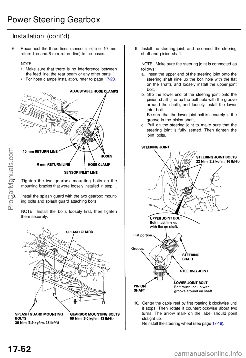
Installation (cont'd )
6. Reconnec t th e thre e line s (senso r inle t line , 1 0 m m
retur n lin e an d 6 m m retur n line ) t o th e hoses .
NOTE:
• Mak e sur e tha t ther e i s n o interferenc e betwee n
th e fee d line , th e rea r bea m o r an y othe r parts .
• Fo r hos e clamp s installation , refe r t o pag e 17-23 . 9
. Instal l th e steerin g joint , an d reconnec t th e steerin g
shaf t an d pinio n shaft .
NOTE : Mak e sur e th e steerin g join t i s connecte d a sfollows :
a. Inser t th e uppe r en d o f th e steerin g join t ont o th e
steerin g shaf t (lin e u p th e bol t hol e wit h th e fla t
o n th e shaft) , an d loosel y instal l th e uppe r join t
bolt,
b. Sli p th e lowe r en d o f th e steerin g join t ont o th e
pinio n shaf t (lin e u p th e bol t hol e wit h th e groov e
aroun d th e shaft) , an d loosel y instal l th e lowe r
joint bolt .
Be sur e tha t th e lowe r join t bol t i s securel y i n th e
groov e in th e pinio n shaft ,
c . Pul l o n th e steerin g join t t o mak e sur e tha t th e
steerin g join t i s full y seated . The n tighte n th e
join t bolts .
Power Steerin g Gearbo x
7. Tighte n th e tw o gearbo x mountin g bolt s o n th e
mountin g bracke t tha t wer e loosel y installe d in ste p 1 .
8 . Instal l th e splas h guar d wit h th e tw o gearbo x mount -
in g bolt s an d splas h guar d attachin g bolts .
NOTE : Instal l th e bolt s loosel y first , the n tighte n
the m securely .
10. Cente r th e cabl e ree l b y firs t rotatin g it clockwis e unti l
i t stops . The n rotat e i t counterclockwis e abou t tw o
turns . Th e arro w mar k o n th e labe l shoul d poin t
straigh t up .
Reinstal l th e steerin g whee l (se e pag e 17-18 ).
ProCarManuals.com