1996 ACURA RL KA9 lock
[x] Cancel search: lockPage 1114 of 1954
Troubleshooting
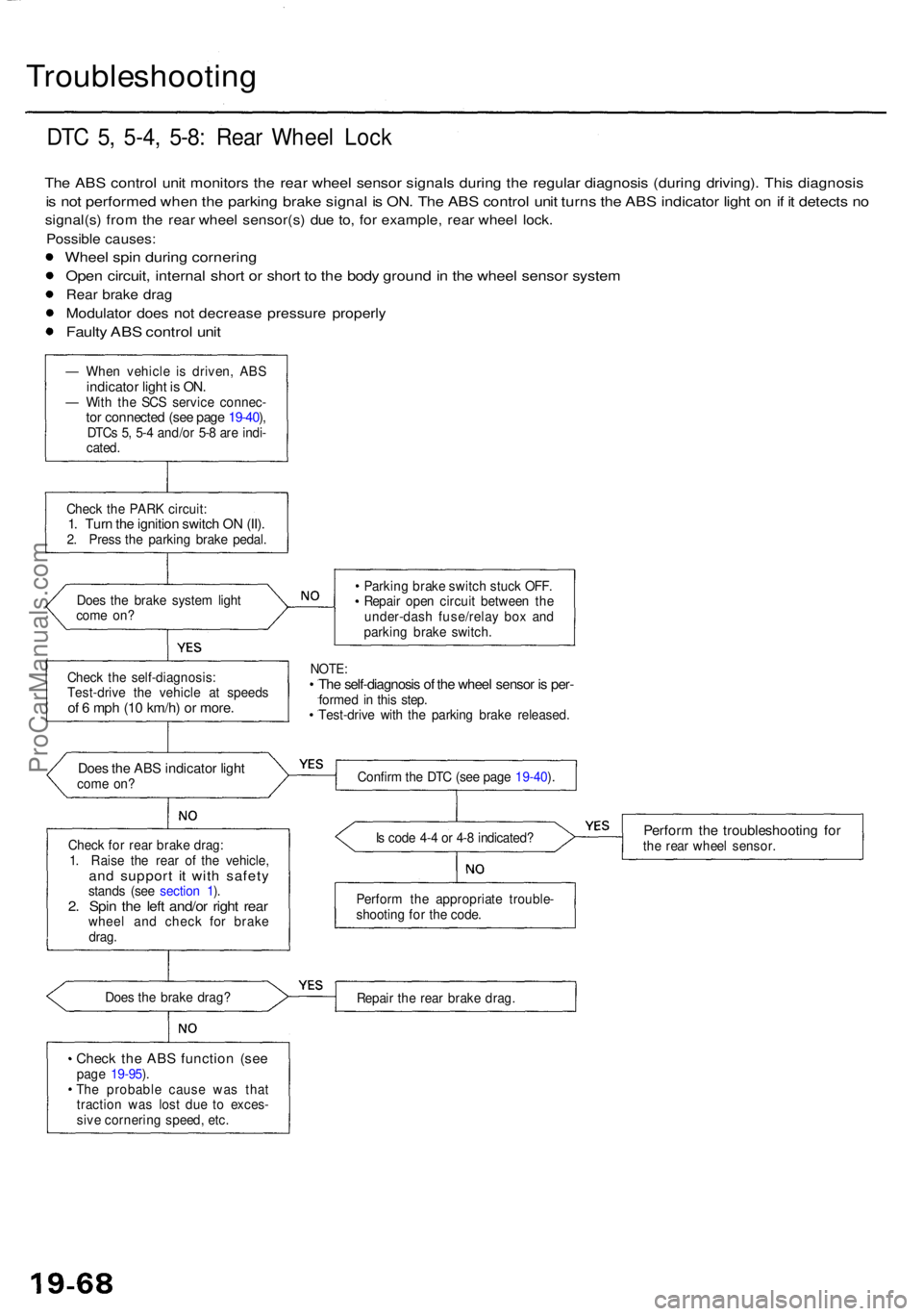
DTC 5 , 5-4 , 5-8 : Rea r Whee l Loc k
The AB S contro l uni t monitor s th e rea r whee l senso r signal s durin g th e regula r diagnosi s (durin g driving) . Thi s diagnosi s
is no t performe d whe n th e parkin g brak e signa l i s ON . Th e AB S contro l uni t turn s th e AB S indicato r ligh t o n if i t detect s n o
signal(s ) fro m th e rea r whee l sensor(s ) du e to , fo r example , rea r whee l lock .
Possibl e causes :
Wheel spi n durin g cornerin g
Open circuit , interna l shor t o r shor t t o th e bod y groun d in th e whee l senso r syste m
Rear brak e dra g
Modulato r doe s no t decreas e pressur e properl y
Faulty AB S contro l uni t
— Whe n vehicl e i s driven , ABSindicato r ligh t i s ON .— Wit h th e SC S servic e connec -tor connecte d (se e pag e 19-40 ),DTC s 5 , 5- 4 and/o r 5- 8 ar e indi -
cated .
Chec k th e PAR K circuit :
1. Tur n th e ignitio n switc h O N (II) .2. Pres s th e parking brake pedal .
Doe s th e brak e syste m ligh t
com e on ? Parkin
g brak e switc h stuc k OFF .
Repai r ope n circui t betwee n th e
under-das h fuse/rela y bo x an d
parkin g brak e switch .
NOTE:The self-diagnosi s o f th e whee l senso r i s per -forme d i n thi s step .
Test-driv e wit h th e parkin g brak e released .
Does th e AB S indicato r ligh tcom e on ?
Chec k fo r rea r brak e drag :
1 . Rais e th e rea r o f th e vehicle ,
and suppor t i t wit h safet ystands (se e sectio n 1 ).2 . Spi n th e lef t and/o r righ t rea rwhee l an d chec k fo r brak e
drag . I
s cod e 4- 4 o r 4- 8 indicated ?
Perform th e troubleshootin g fo rthe rea r whee l sensor .
Perfor m th e appropriat e trouble -
shootin g fo r th e code .
Doe s th e brak e drag ?
Repair th e rea r brak e drag .
Check th e AB S functio n (se epage 19-95 ).
Th e probabl e caus e wa s tha t
tractio n wa s los t du e t o exces -
siv e cornerin g speed , etc .
Chec
k th e self-diagnosis :
Test-driv e th e vehicl e a t speed s
of 6 mp h (1 0 km/h ) o r more .
Confir m th e DT C (se e pag e 19-40 ).
ProCarManuals.com
Page 1142 of 1954
ABS Functio n Tes t (cont'd )
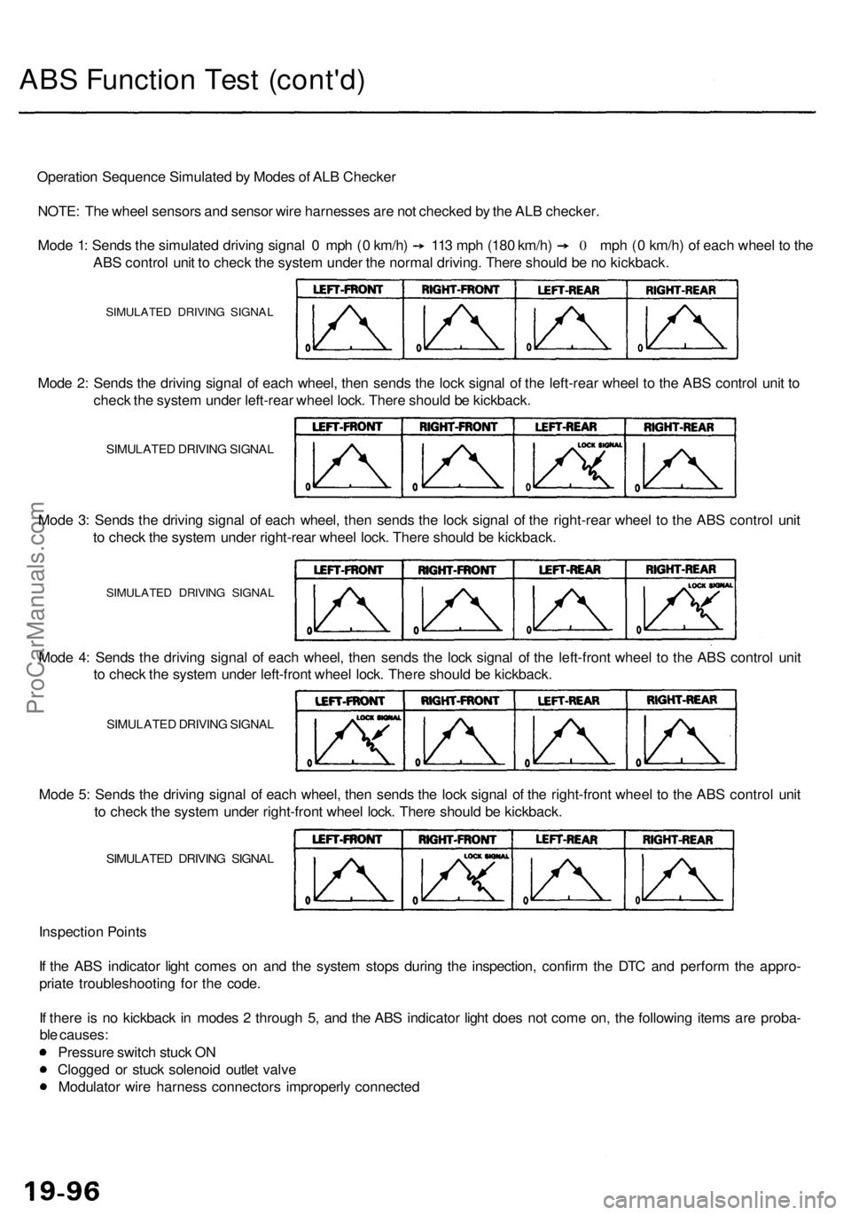
Operatio n Sequenc e Simulate d b y Mode s o f AL B Checke r
NOTE : Th e whee l sensor s an d senso r wir e harnesse s ar e no t checke d b y th e AL B checker .
Mode 1 : Send s th e simulate d drivin g signa l 0 mp h ( 0 km/h ) 11 3 mp h (18 0 km/h ) 0 mph ( 0 km/h ) o f eac h whee l t o th e
AB S contro l uni t t o chec k th e syste m unde r th e norma l driving . Ther e shoul d b e n o kickback .
SIMULATE D DRIVIN G SIGNA L
Mode 2 : Send s th e drivin g signa l o f eac h wheel , the n send s th e loc k signa l o f th e left-rea r whee l t o th e AB S contro l uni t t o
chec k th e syste m unde r left-rea r whee l lock . Ther e shoul d b e kickback .
SIMULATE D DRIVIN G SIGNA L
Mode 3 : Send s th e drivin g signa l o f eac h wheel , the n send s th e loc k signa l o f th e right-rea r whee l t o th e AB S contro l uni t
t o chec k th e syste m unde r right-rea r whee l lock . Ther e shoul d b e kickback .
SIMULATE D DRIVIN G SIGNA L
Inspectio n Point s
I f th e AB S indicato r ligh t come s o n an d th e syste m stop s durin g th e inspection , confir m th e DT C an d perfor m th e appro -
priat e troubleshootin g fo r th e code .
I f ther e is n o kickbac k i n mode s 2 throug h 5 , an d th e AB S indicato r ligh t doe s no t com e on , th e followin g item s ar e proba -
bl e causes :
Pressur e switc h stuc k O N
Clogge d o r stuc k solenoi d outle t valv e
Modulato r wir e harnes s connector s improperl y connecte d
Mod
e 5 : Send s th e drivin g signa l o f eac h wheel , the n send s th e loc k signa l o f th e right-fron t whee l t o th e AB S contro l uni t
t o chec k th e syste m unde r right-fron t whee l lock . Ther e shoul d b e kickback .
SIMULATE D DRIVIN G SIGNA L
Mode 4 : Send s th e drivin g signa l o f eac h wheel , the n send s th e loc k signa l o f th e left-fron t whee l t o th e AB S contro l uni t
t o chec k th e syste m unde r left-fron t whee l lock . Ther e shoul d b e kickback .
SIMULATE D DRIVIN G SIGNA L
ProCarManuals.com
Page 1152 of 1954
Anti-lock Brak e Syste m (ABS )
Features/Constructio n
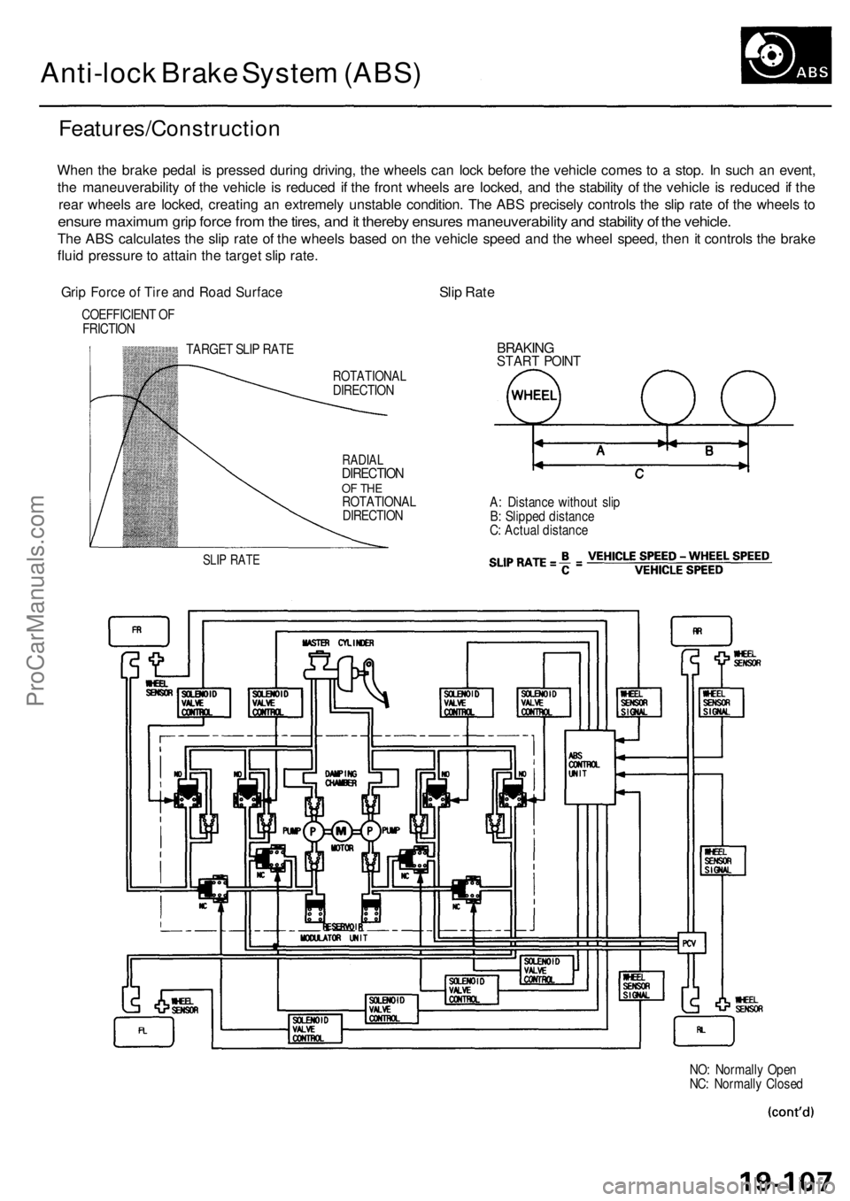
When th e brak e peda l i s presse d durin g driving , th e wheel s ca n loc k befor e th e vehicl e come s t o a stop . I n suc h a n event ,
th e maneuverabilit y o f th e vehicl e i s reduce d i f th e fron t wheel s ar e locked , an d th e stabilit y o f th e vehicl e is reduce d if th e
rea r wheel s ar e locked , creatin g a n extremel y unstabl e condition . Th e AB S precisel y control s th e sli p rat e o f th e wheel s t o
ensur e maximu m gri p forc e fro m th e tires , an d it thereb y ensure s maneuverability and stabilit y o f th e vehicle .
The AB S calculate s th e sli p rat e o f th e wheel s base d o n th e vehicl e spee d an d th e whee l speed , the n it control s th e brak e
flui d pressur e to attai n th e targe t sli p rate .
Grip Forc e o f Tir e an d Roa d Surfac eSlip Rat e
COEFFICIEN T O F
FRICTIO N
TARGET SLI P RAT E
SLIP RAT E
ROTATIONA LDIRECTION
RADIALDIRECTIO NOF TH EROTATIONA L
DIRECTIO N
BRAKINGSTART POIN T
A: Distanc e withou t sli p
B : Slippe d distanc e
C : Actua l distanc e
NO: Normall y Ope n
NC : Normall y Close d
ProCarManuals.com
Page 1153 of 1954
Anti-lock Brake System (ABS)
Features/Construction (cont'd)
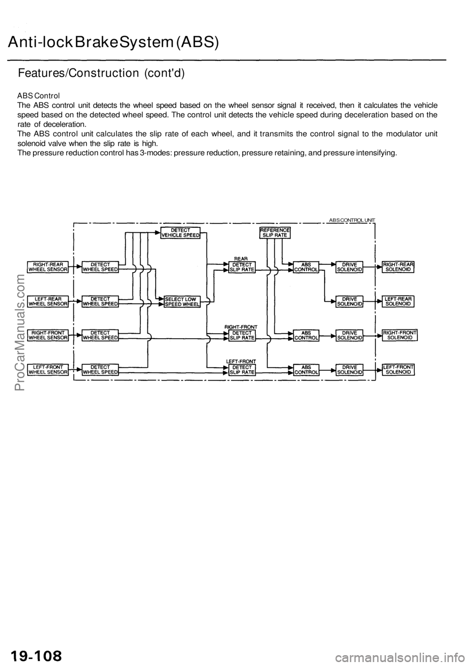
ABS Control
The ABS control unit detects the wheel speed based on the wheel sensor signal it received, then it calculates the vehicle
speed based on the detected wheel speed. The control unit detects the vehicle speed during deceleration based on the
rate of deceleration.
The ABS control unit calculates the slip rate of each wheel, and it transmits the control signal to the modulator unit
solenoid valve when the slip rate is high.
The pressure reduction control has 3-modes: pressure reduction, pressure retaining, and pressure intensifying.
ABS CONTROL UNITProCarManuals.com
Page 1154 of 1954
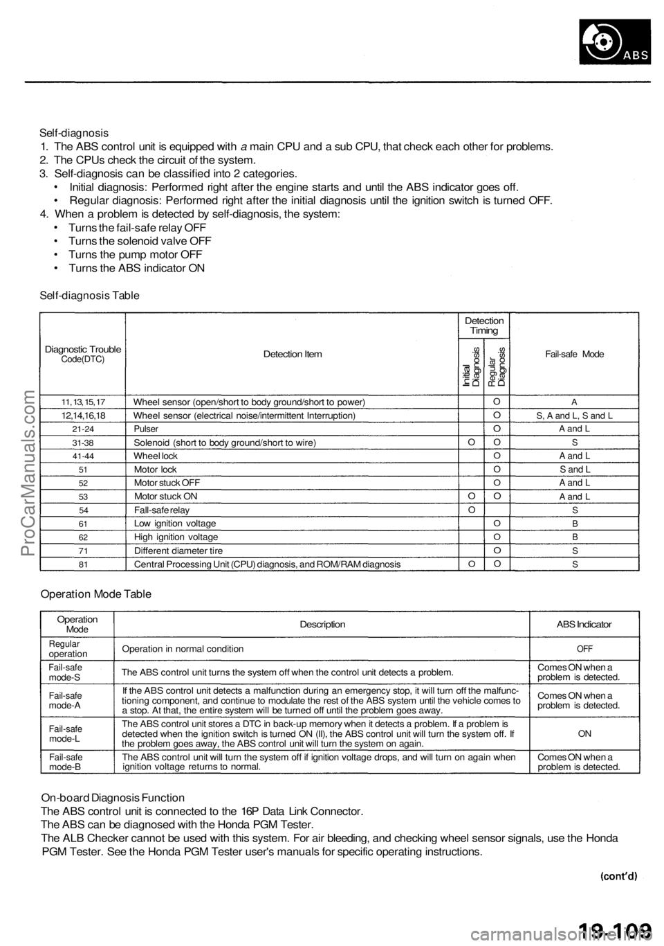
Self-diagnosis
1. The ABS control unit is equipped with a main CPU and a sub CPU, that check each other for problems.
2. The CPUs check the circuit of the system.
3. Self-diagnosis can be classified into 2 categories.
Initial diagnosis: Performed right after the engine starts and until the ABS indicator goes off.
Regular diagnosis: Performed right after the initial diagnosis until the ignition switch is turned OFF.
4. When a problem is detected by self-diagnosis, the system:
Turns the fail-safe relay OFF
Turns the solenoid valve OFF
Turns the pump motor OFF
Turns the ABS indicator ON
Self-diagnosis Table
Diagnostic Trouble
Code(DTC)
11, 13, 15, 17
12,14,16,18
21-24
31-38
41-44
51
52
53
54
61
62
71
81
Detection Item
Wheel sensor (open/short to body ground/short to power)
Wheel sensor (electrical noise/intermittent Interruption)
Pulser
Solenoid (short to body ground/short to wire)
Wheel lock
Motor lock
Motor stuck OFF
Motor stuck ON
Fall-safe relay
Low ignition voltage
High ignition voltage
Different diameter tire
Central Processing Unit (CPU) diagnosis, and ROM/RAM diagnosis
Detection
Timing
Initial
Diagnosis
O
O
O
O
Regular
Diagnosis
O
O
O
O
O
O
O
O
O
O
O
O
Fail-safe Mode
A
S, A and L, S and L
A and L
S
A and L
S and L
A and L
A and L
S
B
B
S
S
Operation Mode Table
Operation
Mode
Regular
operation
Fail-safe
mode-S
Fail-safe
mode-A
Fail-safe
mode-L
Fail-safe
mode-B
Description
Operation in normal condition
The ABS control unit turns the system off when the control unit detects a problem.
If the ABS control unit detects a malfunction during an emergency stop, it will turn off the malfunc-
tioning component, and continue to modulate the rest of the ABS system until the vehicle comes to
a stop. At that, the entire system will be turned off until the problem goes away.
The ABS control unit stores a DTC in back-up memory when it detects a problem. If a problem is
detected when the ignition switch is turned ON (II), the ABS control unit will turn the system off. If
the problem goes away, the ABS control unit will turn the system on again.
The ABS control unit will turn the system off if ignition voltage drops, and will turn on again when
ignition voltage returns to normal.
ABS
Indicator
OFF
Comes ON when a
problem is detected.
Comes ON when a
problem is detected.
ON
Comes ON when a
problem is detected.
On-board Diagnosis Function
The ABS control unit is connected to the 16P Data Link Connector.
The ABS can be diagnosed with the Honda PGM Tester.
The ALB Checker cannot be used with this system. For air bleeding, and checking wheel sensor signals, use the Honda
PGM Tester. See the Honda PGM Tester user's manuals for specific operating instructions.
ProCarManuals.com
Page 1155 of 1954
Anti-lock Brak e Syste m (ABS )
Features/Constructio n (cont'd )
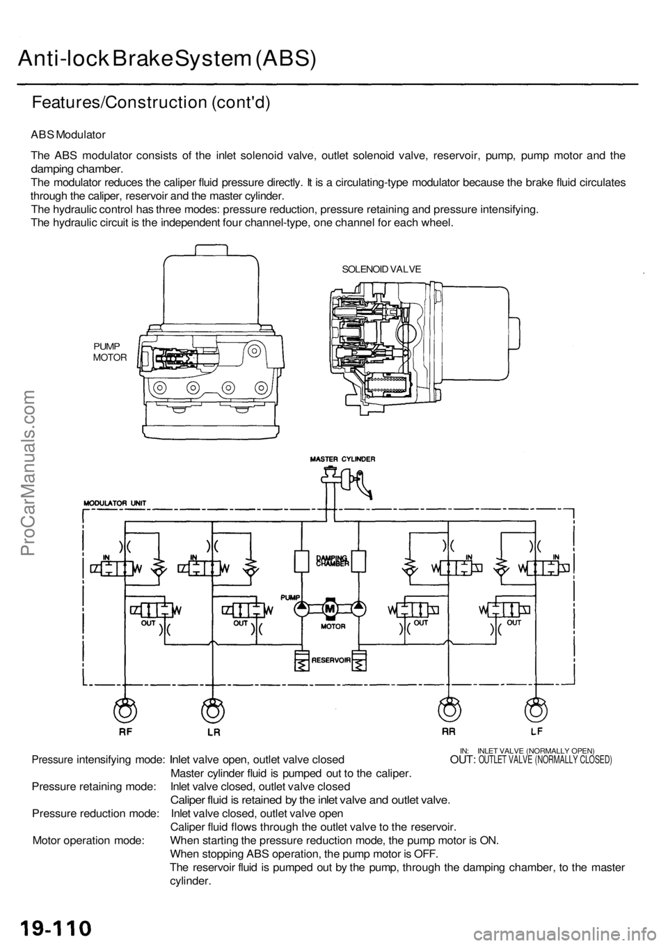
ABS Modulato r
Th e AB S modulato r consist s of the inle t solenoi d valve , outle t solenoi d valve , reservoir , pump , pum p moto r an d th e
dampin g chamber .
The modulato r reduce s th e calipe r flui d pressur e directly . I t i s a circulating-typ e modulato r becaus e th e brak e flui d circulate s
throug h th e caliper , reservoi r an d th e maste r cylinder .
Th e hydrauli c contro l ha s thre e modes : pressur e reduction , pressur e retainin g an d pressur e intensifying .
Th e hydrauli c circui t i s th e independen t fou r channel-type , on e channe l fo r eac h wheel .
SOLENOI D VALV E
PUMPMOTO R
IN: INLE T VALV E (NORMALL Y OPEN )Pressur e intensifyin g mode : Inlet valv e open , outle t valv e close d OUT : OUTLET VALV E (NORMALL Y CLOSED )
Master cylinde r flui d is pumpe d ou t t o th e caliper .
Pressur e retainin g mode : Inle t valv e closed , outle t valv e close d
Caliper flui d is retaine d b y th e inle t valv e an d outle t valve .
Pressur e reductio n mode : Inle t valv e closed , outle t valv e ope n
Calipe r flui d flow s throug h th e outle t valv e to th e reservoir .
Whe n startin g th e pressur e reductio n mode , th e pum p moto r i s ON .
Whe n stoppin g AB S operation , th e pum p moto r i s OFF .
Th e reservoi r flui d is pumpe d ou t b y th e pump , throug h th e dampin g chamber , t o th e maste r
cylinder .
Moto
r operatio n mode :
ProCarManuals.com
Page 1192 of 1954
Construction and Function
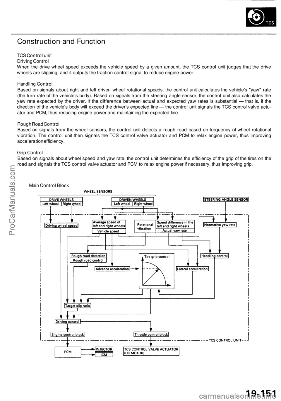
TCS Control unit
Driving Control
When the drive wheel speed exceeds the vehicle speed by a given amount, the TCS control unit judges that the drive
wheels are slipping, and it outputs the traction control signal to reduce engine power.
Handling Control
Based on signals about right and left driven wheel rotational speeds, the control unit calculates the vehicle's "yaw" rate
(the turn rate of the vehicle's body). Based on signals from the steering angle sensor, the control unit also calculates the
yaw rate expected by the driver. If the difference between actual and expected yaw rates is substantial — that is, if the
direction of the vehicle's body will exceed the driver's expected line — the control unit signals the TCS control valve actu-
ator and PCM, thus reducing engine power and maintaining the expected line.
Rough Road Control
Based on signals from the wheel sensors, the control unit detects a rough road based on frequency of wheel rotational
vibration. The control unit then signals the TCS control valve actuator and PCM to relax engine power, thus improving
acceleration efficiency.
Grip Control
Based on signals about wheel speed and yaw rate, the control unit determines the efficiency of the grip of the tires on the
road and signals the TCS control valve actuator and PCM to relax engine power if necessary, thus improving grip.
Main Control BlockProCarManuals.com
Page 1230 of 1954
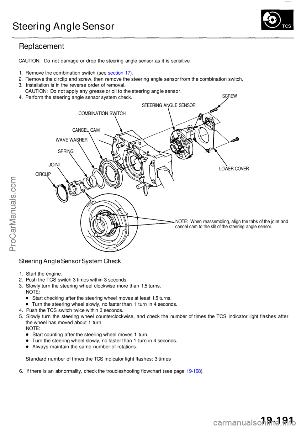
Steering Angl e Senso r
Replacemen t
SCREW
CAUTION : D o no t damag e o r dro p th e steerin g angl e senso r a s it i s sensitive .
1 . Remov e th e combinatio n switc h (se e sectio n 17 ).
2 . Remov e th e circli p an d screw , the n remov e th e steerin g angl e senso r fro m th e combinatio n switch .
3 . Installatio n i s i n th e revers e orde r o f removal .
CAUTION : D o no t appl y an y greas e o r oi l t o th e steerin g angl e sensor .
4 . Perfor m th e steerin g angl e senso r syste m check .
STEERIN G ANGL E SENSO R
COMBINATIO N SWITC H
CANCE L CA M
WAV E WASHE R
SPRING
LOWER COVE RJOINT
CIRCLI P
NOTE: Whe n reassembling , alig n th e tab s o f th e join t an dcance l ca m to th e sli t o f th e steerin g angl e sensor .
Steering Angl e Senso r Syste m Chec k
1. Star t th e engine .
2 . Pus h th e TC S switc h 3 time s withi n 3 seconds .
3 . Slowl y tur n th e steerin g whee l clockwis e mor e tha n 1. 5 turns .
NOTE :
Start checkin g afte r th e steerin g whee l move s a t leas t 1. 5 turns .
Tur n th e steerin g whee l slowly , n o faste r tha n 1 tur n in 4 seconds .
4 . Pus h th e TC S switc h twic e withi n 3 seconds .
5 . Slowl y tur n th e steerin g whee l counterclockwise , an d chec k th e numbe r o f time s th e TC S indicato r ligh t flashe s afte r
th e whee l ha s move d abou t 1 turn .
NOTE :
Start countin g afte r th e steerin g whee l move s 1 turn .
Tur n th e steerin g whee l slowly , n o faste r tha n 1 tur n in 4 seconds .
Alway s maintai n th e sam e numbe r o f rotations .
Standar d numbe r o f time s th e TC S indicato r ligh t flashes : 3 time s
6 . I f ther e is a n abnormality , chec k th e troubleshootin g flowchar t (se e pag e 19-168 ).
ProCarManuals.com