1996 ACURA RL KA9 lock
[x] Cancel search: lockPage 1426 of 1954
A/C Pressure Switch
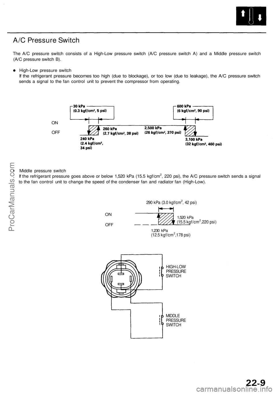
The A/C pressure switch consists of a High-Low pressure switch (A/C pressure switch A) and a Middle pressure switch
(A/C pressure switch B).
High-Low pressure switch
If the refrigerant pressure becomes too high (due to blockage), or too low (due to leakage), the A/C pressure switch
sends a signal to the fan control unit to prevent the compressor from operating.
ON
OFF
• Middle pressure switch
If the refrigerant pressure goes above or below 1,520 kPa (15.5 kgf/cm2, 220 psi), the A/C pressure switch sends a signal
to the fan control unit to change the speed of the condenser fan and radiator fan (High-Low).
290 kPa (3.0 kgf/cm2, 42 psi)
ON
OFF
1,230
kPa
(12.5 kgf/cm2,178 psi)
1,520
kPa
(15.5 kgf/cm2,220 psi)
MIDDLE
PRESSURE
SWITCH
HIGH-LOW
PRESSURE
SWITCHProCarManuals.com
Page 1471 of 1954
Climate Contro l Uni t
Face Panel/Butto n Replacemen t
CAUTION:
Before replacin g fac e pane l o r buttons , discharg e th e
stati c electricit y (whic h accumulate d o n yo u whe n
yo u remove d th e climat e contro l unit ) b y touchin g
th e doo r strike r o r othe r bod y parts .
D o no t touc h th e electroni c component s o n th e
printe d circui t boar d in th e climat e contro l unit .
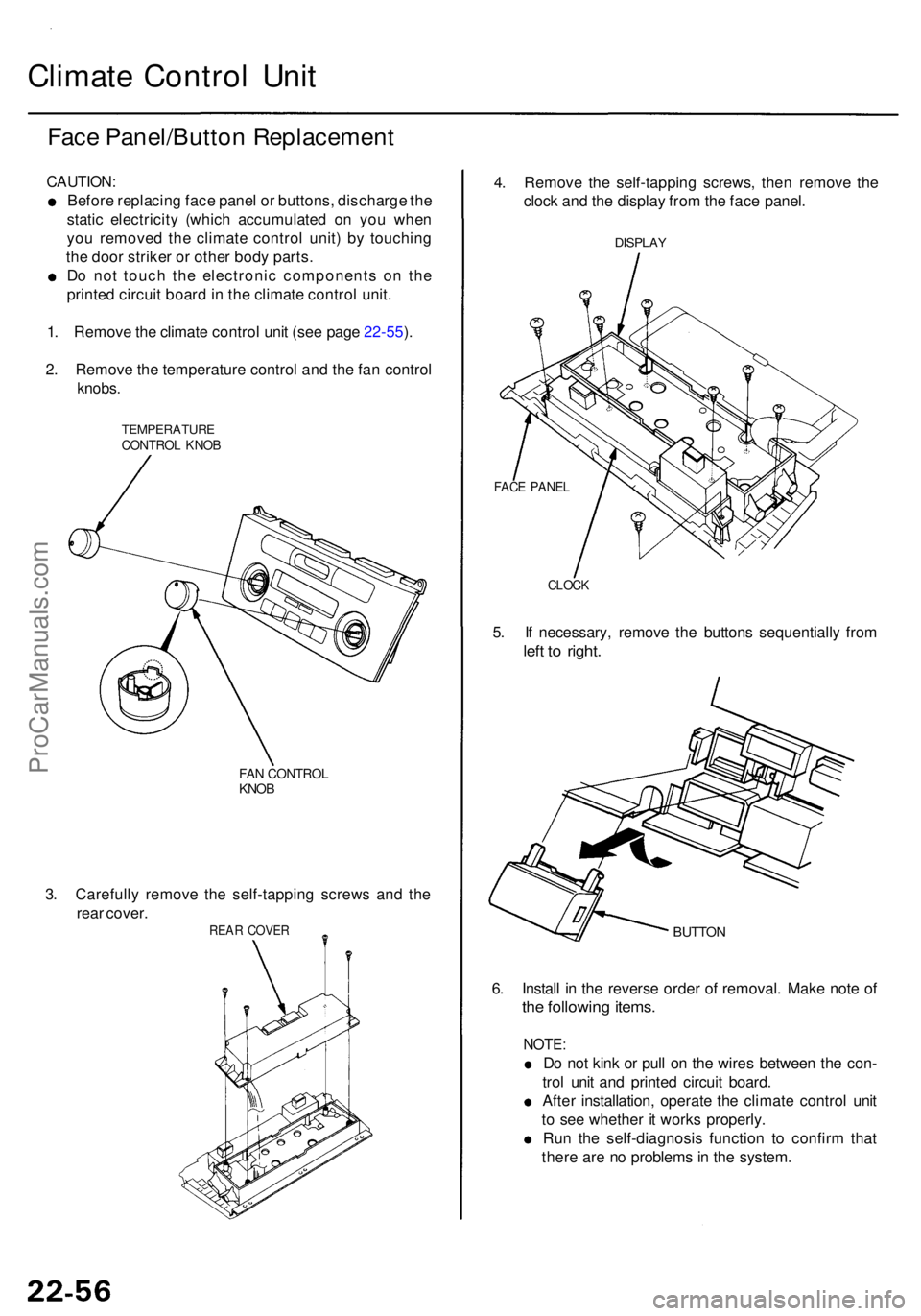
1 . Remov e th e climat e contro l uni t (se e pag e 22-55 ).
2 . Remov e th e temperatur e contro l an d th e fa n contro l
knobs.
TEMPERATUR ECONTROL KNO B
FAN CONTRO LKNOB
3. Carefull y remov e th e self-tappin g screw s an d th e
rea r cover .
REAR COVE R
4. Remov e th e self-tappin g screws , the n remov e th e
cloc k an d th e displa y fro m th e fac e panel .
DISPLA Y
CLOCK
5. I f necessary , remov e th e button s sequentiall y fro m
left t o right .
BUTTO N
6. Instal l i n th e revers e orde r o f removal . Mak e not e o f
the followin g items .
NOTE :
Do no t kin k o r pul l o n th e wire s betwee n th e con -
tro l uni t an d printe d circui t board .
Afte r installation , operat e th e climat e contro l uni t
t o se e whethe r i t work s properly .
Ru n th e self-diagnosi s functio n t o confir m tha t
ther e ar e n o problem s in th e system .
FACE PANE L
ProCarManuals.com
Page 1478 of 1954
Evaporator Temperatur e
Sensor Powe r Transisto r
Test
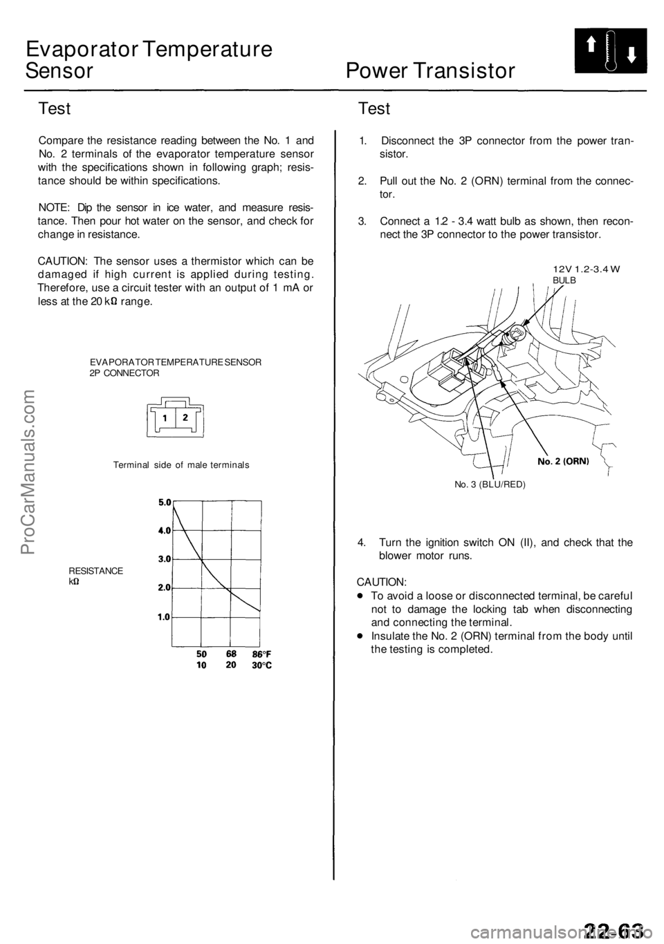
Compar e th e resistanc e readin g betwee n th e No . 1 an d
No . 2 terminal s o f th e evaporato r temperatur e senso r
wit h th e specification s show n i n followin g graph ; resis -
tanc e shoul d b e withi n specifications .
NOTE : Di p th e senso r i n ic e water , an d measur e resis -
tance . The n pou r ho t wate r o n th e sensor , an d chec k fo r
chang e in resistance .
CAUTION : Th e senso r use s a thermisto r whic h ca n b e
damage d i f hig h curren t i s applie d durin g testing .
Therefore , us e a circui t teste r wit h a n outpu t o f 1 m A o r
les s a t th e 2 0 k range .
EVAPORATO R TEMPERATUR E SENSO R
2 P CONNECTO R
Test
Termina l sid e o f mal e terminal s
RESISTANC E
k
1. Disconnec t th e 3 P connecto r fro m th e powe r tran -
sistor .
2 . Pul l ou t th e No . 2 (ORN ) termina l fro m th e connec -
tor.
3. Connec t a 1. 2 - 3. 4 wat t bul b a s shown , the n recon -
nec t th e 3 P connecto r t o th e powe r transistor .
12V 1.2-3. 4 WBUL B
No. 3 (BLU/RED )
4. Tur n th e ignitio n switc h O N (II) , an d chec k tha t th e
blowe r moto r runs .
CAUTION :
T o avoi d a loos e o r disconnecte d terminal , b e carefu l
no t t o damag e th e lockin g ta b whe n disconnectin g
an d connectin g th e terminal .
Insulat e th e No . 2 (ORN ) termina l fro m th e bod y unti l
th e testin g is completed .
ProCarManuals.com
Page 1507 of 1954
Troubleshooting
Tips an d Precaution s
Before Troubleshootin g
• Chec k applicabl e fuse s i n th e appropriat e fuse/rela y
box.
• Chec k th e batter y fo r damage , stat e o f charge , an d
clea n an d tigh t connections .
• Chec k th e alternato r bel t tension .
CAUTION :
• D o no t quick-charg e a batter y unles s th e batter y
groun d cabl e ha s bee n disconnected , otherwis e yo u
wil l damag e th e alternato r diodes .
• D o no t attemp t t o cran k th e engin e wit h th e batter y
groun d cabl e loosel y connecte d o r yo u wil l severel y
damag e th e wiring .
Handlin g Connector s
• Mak e sur e th e connector s ar e clea n an d hav e n o loos e
wire terminals .
• Mak e sur e multipl e cavit y connector s ar e packe d wit h
greas e (excep t watertigh t connectors) .
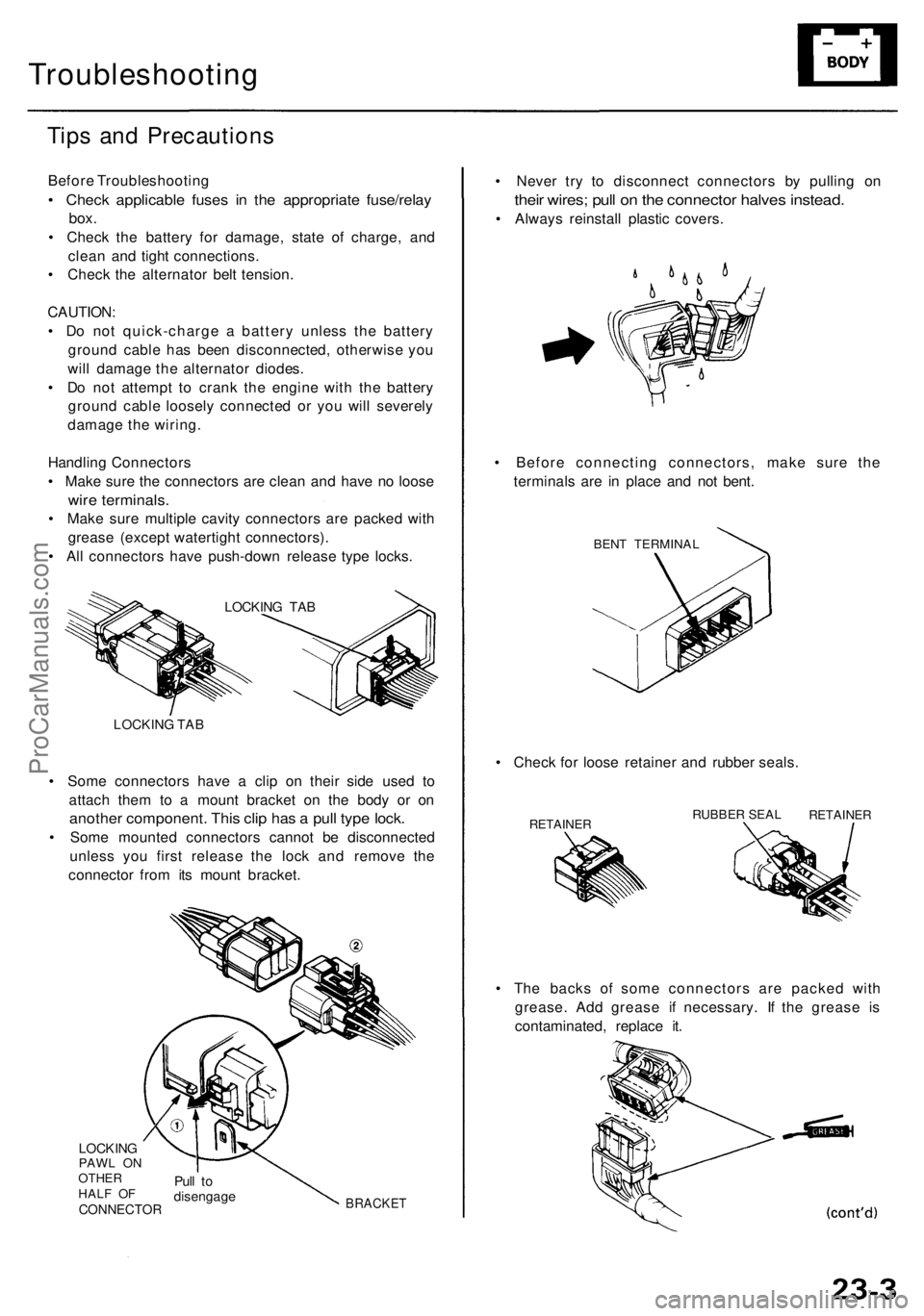
• Al l connector s hav e push-dow n releas e typ e locks .
LOCKIN G TA B
LOCKIN G TA B
• Som e connector s hav e a cli p o n thei r sid e use d t o
attac h the m t o a moun t bracke t o n th e bod y o r o n
anothe r component . Thi s cli p ha s a pul l typ e lock .
• Som e mounte d connector s canno t b e disconnecte d
unles s yo u firs t releas e th e loc k an d remov e th e
connecto r fro m it s moun t bracket .
LOCKINGPAWL O N
OTHE R
HAL F O F
CONNECTO R
Pull t odisengag eBRACKET
• Th e back s o f som e connector s ar e packe d wit h
grease . Ad d greas e i f necessary . I f th e greas e i s
contaminated , replac e it .
•
Chec k fo r loos e retaine r an d rubbe r seals .
RETAINE RRUBBER SEA LRETAINE R
• Neve r tr y t o disconnec t connector s b y pullin g o n
thei r wires ; pul l o n th e connecto r halve s instead .
• Alway s reinstal l plasti c covers .
• Befor e connectin g connectors , mak e sur e th e
terminal s ar e i n plac e an d no t bent .
BENT TERMINA L
ProCarManuals.com
Page 1508 of 1954
Troubleshooting
Tips an d Precaution s (cont'd )
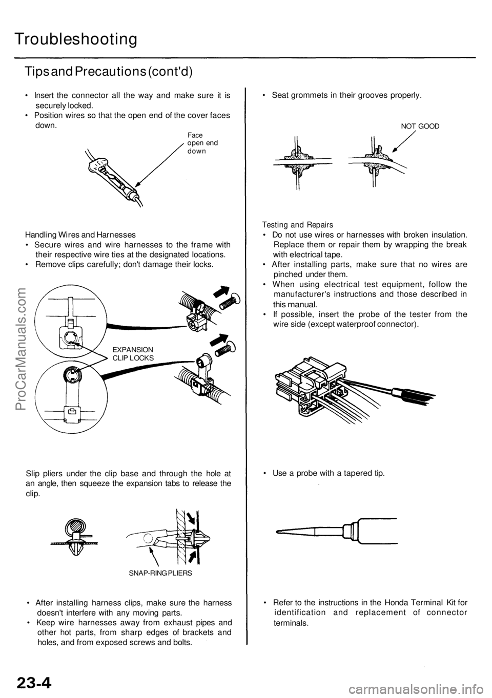
• Inser t th e connecto r al l th e wa y an d mak e sur e i t i s
securel y locked .
• Positio n wire s s o tha t th e ope n en d o f th e cove r face s
down .
Faceope n en ddow n
Handlin g Wire s an d Harnesse s
• Secur e wire s an d wir e harnesse s t o th e fram e wit h
thei r respectiv e wir e tie s a t th e designate d locations .
• Remov e clip s carefully ; don' t damag e thei r locks .
EXPANSIO NCLIP LOCK S
Slip plier s unde r th e cli p bas e an d throug h th e hol e a t
a n angle , the n squeez e th e expansio n tab s t o releas e th e
clip .
SNAP-RIN G PLIER S
• Afte r installin g harnes s clips , mak e sur e th e harnes s
doesn' t interfer e wit h an y movin g parts .
• Kee p wir e harnesse s awa y fro m exhaus t pipe s an d
othe r ho t parts , fro m shar p edge s o f bracket s an d
holes , an d fro m expose d screw s an d bolts . •
Refe r t o th e instruction s i n th e Hond a Termina l Ki t fo r
identificatio n an d replacemen t o f connecto r
terminals .
•
Us e a prob e wit h a tapere d tip .
•
Sea t grommet s i n thei r groove s properly .
NOT GOO D
Testin g an d Repair s
• D o no t us e wire s o r harnesse s wit h broke n insulation .
Replac e the m o r repai r the m b y wrappin g th e brea k
wit h electrica l tape .
• Afte r installin g parts , mak e sur e tha t n o wire s ar e
pinche d unde r them .
• Whe n usin g electrica l tes t equipment , follo w th e
manufacturer' s instruction s an d thos e describe d i n
thi s manual .
• I f possible , inser t th e prob e of the teste r fro m th e
wir e sid e (excep t waterproo f connector) .
ProCarManuals.com
Page 1521 of 1954
8. Afte r reconnectin g th e battery , ente r th e anti-thef t
cod e fo r th e radi o an d th e navigatio n system , the n
ente r th e customer' s radi o statio n presets .
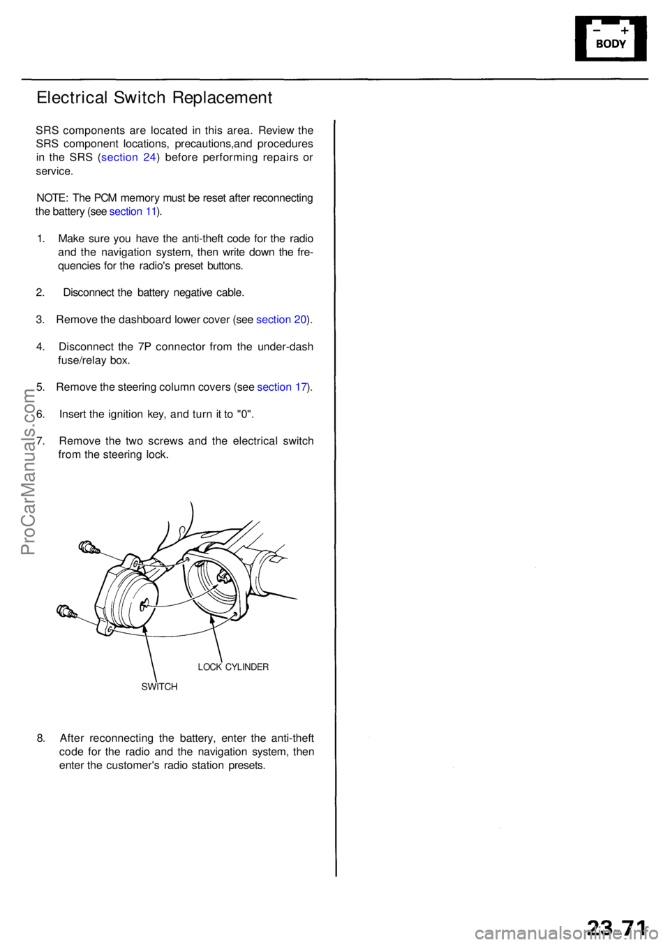
SWITCH
LOCK CYLINDE R
Electrical Switc h Replacemen t
SRS component s ar e locate d i n thi s area . Review the
SR S componen t locations , precautions,an d procedure s
i n th e SR S ( sectio n 24 ) befor e performin g repair s o r
service .
NOTE: Th e PC M memor y mus t b e rese t afte r reconnectin g
th e batter y (se e sectio n 11 ).
1 . Mak e sur e yo u hav e th e anti-thef t cod e fo r th e radi o
an d th e navigatio n system , the n writ e dow n th e fre -
quencie s fo r th e radio' s prese t buttons .
2 . Disconnec t th e batter y negativ e cable .
3 . Remov e th e dashboar d lowe r cove r (se e sectio n 20 ).
4 . Disconnec t th e 7 P connecto r fro m th e under-das h
fuse/rela y box .
5 . Remov e th e steerin g colum n cover s (se e sectio n 17 ).
6 . Inser t th e ignitio n key , an d tur n it t o "0" .
7 . Remov e th e tw o screw s an d th e electrica l switc h
fro m th e steerin g lock .
ProCarManuals.com
Page 1530 of 1954
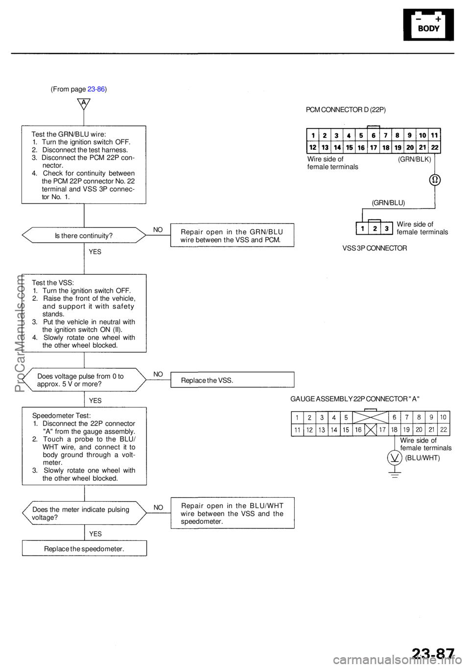
(From page 23-86)
Tes t th e GRN/BL U wire :
1 . Tur n th e ignitio n switc h OFF .
2 . Disconnec t th e tes t harness .
3 . Disconnec t th e PC M 22 P con -
nector .4. Chec k fo r continuit y betwee n
th e PC M 22 P connecto r No . 2 2
termina l an d VS S 3 P connec -
tor No . 1 .
Is ther e continuity ?NO
YE S
Repai r ope n i n th e GRN/BL U
wir e betwee n th e VS S an d PCM . PC
M CONNECTO R D (22P )
Wir e sid e o f
femal e terminal s
VS S 3P CONNECTO R
(GRN/BLK)
(GRN/BLU)
Wir e sid e o f
femal e terminal s
Replac e th e VSS .
GAUGE ASSEMBL Y 22 P CONNECTO R "A "
Wir e sid e o f
femal e terminal s
(BLU/WHT )
Repair ope n i n th e BLU/WH T
wir e betwee n th e VS S an d th e
speedometer .
Doe
s th e mete r indicat e pulsin g
voltage ?
YES
NO
Replac e th e speedometer .
Speedomete
r Test :
1 . Disconnec t th e 22 P connecto r
"A " fro m th e gaug e assembly .
2 . Touc h a prob e t o th e BLU /
WH T wire , an d connec t i t t o
bod y groun d throug h a volt -
meter .
3 . Slowl y rotat e on e whee l wit h
th e othe r whee l blocked .
Doe
s voltag e puls e fro m 0 t o
approx . 5 V or more ?
Tes
t th e VSS :
1 . Tur n th e ignitio n switc h OFF .
2 . Rais e th e fron t o f th e vehicle ,
and suppor t i t wit h safet ystands.
3 . Pu t th e vehicl e i n neutra l wit h
th e ignitio n switc h O N (II) .
4 . Slowl y rotat e on e whee l wit h
th e othe r whee l blocked .
NO
YE S
ProCarManuals.com
Page 1548 of 1954
Headlights
HID Bul b Remova l ('9 9 - 0 4 models )
A transien t hig h tensio n (25,00 0 V ) occur s
a t th e bul b socket s o f th e hig h intensit y discharg e (HID )
lamp s whe n th e combinatio n ligh t switc h is turne d ON .
I t ma y caus e seriou s electrica l shoc k o r electrocutio n if
yo u d o no t observ e th e caution s below .
CAUTION :
• Neve r tur n o n th e combinatio n ligh t switc h befor e
fittin g th e HI D bulb s t o thei r bul b socket s an d com -
pletin g th e reassembl y o f th e headligh t assembly .
• T o preven t electrocution , d o no t servic e th e head -
light s assembl y i n we t conditions , suc h a s rai n o r
snow , nea r a sprinkle r system , o r whe n you r hand s
are wet .
• D o no t touc h th e surfac e o f th e HI D bulb s wit h you r
bar e hand s an d d o no t stai n i t wit h an y oil s an d
fats .
• D o no t disassembl e th e inverte r uni t an d th e ignite r
unit .
• D o no t tur n o n th e HI D bul b b y usin g a powe r
sourc e othe r tha n th e batter y mounte d o n you r
vehicle .
1. Mak e sur e yo u hav e th e anti-thef t cod e fo r th e radi o
an d th e navigatio n system , the n writ e dow n th e fre -
quencie s fo r th e radio' s prese t buttons .
2. Tur n th e combinatio n ligh t switc h OFF .
3. Disconnec t th e batter y negativ e cable , the n discon -
nec t th e positiv e cable .
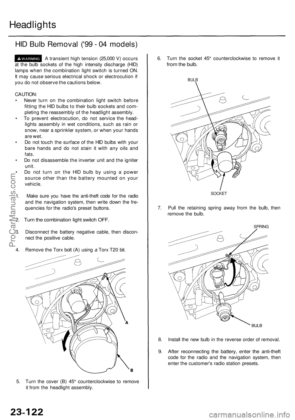
4 . Remov e th e Tor x bol t (A ) usin g a Tor x T2 0 bit .
5 . Tur n th e cove r (B ) 45 ° counterclockwis e t o remov e
i t fro m th e headligh t assembly . 8
. Instal l th e ne w bul b in th e revers e orde r o f removal .
9. Afte r reconnectin g th e battery , ente r th e anti-thef t
code fo r th e radi o an d th e navigatio n system , the n
ente r th e customer' s radi o statio n presets .
BULB
SPRIN G
6. Tur n th e socke t 45 ° counterclockwis e t o remov e i t
fro m th e bulb .
BULB
7. Pul l th e retainin g sprin g awa y fro m th e bulb , the n
remov e th e bulb .
SOCKE T
ProCarManuals.com