1996 ACURA RL KA9 lock
[x] Cancel search: lockPage 1718 of 1954
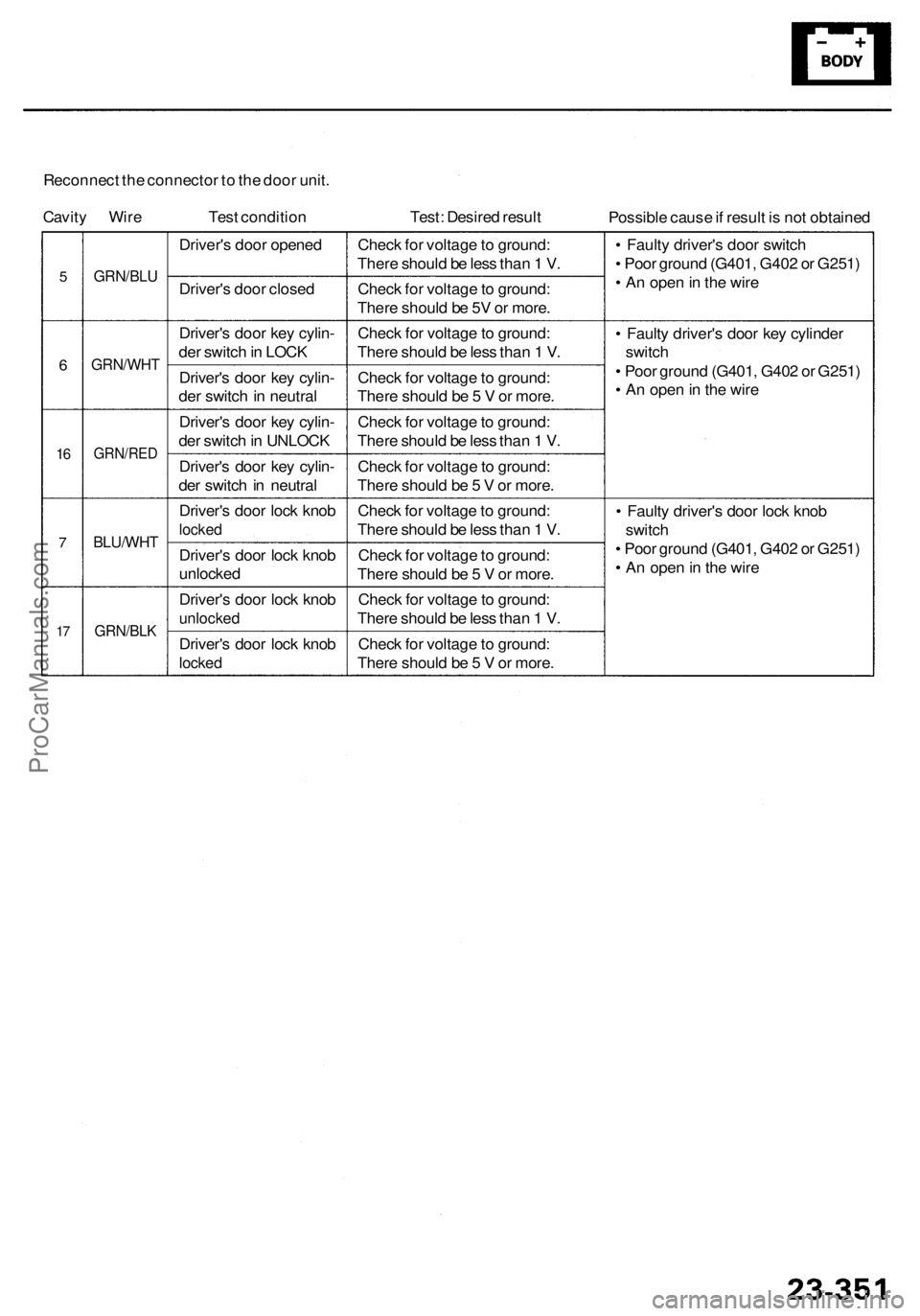
Reconnect th e connecto r t o th e doo r unit .
Cavit y Wir e Test conditio n Test: Desire d resul t
Possible caus e if resul t i s no t obtaine d
5
6
16
7
17
GRN/BL U
GRN/WH T
GRN/RED
BLU/WHT
GRN/BLK
Driver's doo r opene d
Driver' s doo r close d
Driver' s doo r ke y cylin -
de r switc h in LOC K
Driver' s doo r ke y cylin -
de r switc h in neutra l
Driver' s doo r ke y cylin -
de r switc h in UNLOC K
Driver' s doo r ke y cylin -
de r switc h in neutra l
Driver' s doo r loc k kno b
locke d
Driver' s doo r loc k kno b
unlocke d
Driver' s doo r loc k kno b
unlocke d
Driver's doo r loc k kno b
locke d
Chec k fo r voltag e to ground :
Ther e shoul d b e les s tha n 1 V .
Chec k fo r voltag e to ground :
Ther e shoul d b e 5 V o r more .
Chec k fo r voltag e to ground :
Ther e shoul d b e les s tha n 1 V .
Chec k fo r voltag e to ground :
Ther e shoul d b e 5 V or more .
Chec k fo r voltag e to ground :
Ther e shoul d b e les s tha n 1 V .
Chec k fo r voltag e to ground :
Ther e shoul d b e 5 V or more .
Chec k fo r voltag e to ground :
Ther e shoul d b e les s tha n 1 V .
Chec k fo r voltag e to ground :
Ther e shoul d b e 5 V or more .
Chec k fo r voltag e to ground :
Ther e shoul d b e les s tha n 1 V .
Chec k fo r voltag e to ground :
Ther e shoul d b e 5 V or more . •
Fault y driver' s doo r switc h
• Poo r groun d (G401 , G40 2 o r G251 )
• A n ope n in th e wir e
• Fault y driver' s doo r ke y cylinde r
switc h
• Poo r groun d (G401 , G40 2 o r G251 )
• A n ope n in th e wir e
• Fault y driver' s doo r loc k kno b
switc h
• Poo r groun d (G401 , G40 2 o r G251 )
• A n ope n in th e wir e
ProCarManuals.com
Page 1731 of 1954
Description
Navigation Functio n (cont'd )
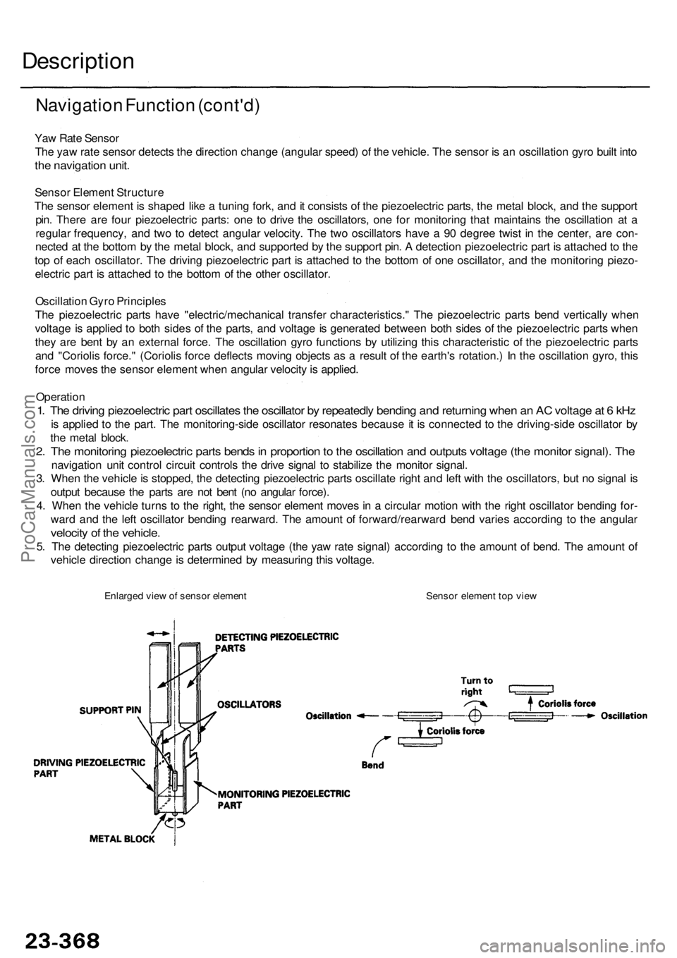
Yaw Rat e Senso r
Th e ya w rat e senso r detect s th e directio n chang e (angula r speed ) o f th e vehicle . Th e senso r i s a n oscillatio n gyr o buil t int o
the navigatio n unit .
Senso r Elemen t Structur e
Th e senso r elemen t i s shape d lik e a tunin g fork , an d it consist s o f th e piezoelectri c parts , th e meta l block , an d th e suppor t
pin . Ther e ar e fou r piezoelectri c parts : on e t o driv e th e oscillators , on e fo r monitorin g tha t maintain s th e oscillatio n a t a
regula r frequency , an d tw o t o detec t angula r velocity . Th e tw o oscillator s hav e a 90 degre e twis t i n th e center , ar e con -
necte d a t th e botto m b y th e meta l block , an d supporte d b y th e suppor t pin . A detectio n piezoelectri c par t i s attache d to th e
to p o f eac h oscillator . Th e drivin g piezoelectri c par t i s attache d t o th e botto m o f on e oscillator , an d th e monitoring piezo-
electri c par t i s attache d t o th e botto m o f th e othe r oscillator .
Oscillatio n Gyr o Principle s
Th e piezoelectri c part s hav e "electric/mechanica l transfe r characteristics. " Th e piezoelectri c part s ben d verticall y whe n
voltag e is applie d t o bot h side s o f th e parts , an d voltag e is generate d betwee n bot h side s o f th e piezoelectri c part s whe n
the y ar e ben t b y a n externa l force . Th e oscillatio n gyr o function s b y utilizin g thi s characteristi c o f th e piezoelectri c part s
an d "Corioli s force. " (Corioli s forc e deflect s movin g object s a s a resul t o f th e earth' s rotation. ) I n th e oscillation gyro, thi s
forc e move s th e senso r elemen t whe n angula r velocit y is applied .
Operatio n
1. Th e drivin g piezoelectri c par t oscillate s th e oscillato r b y repeatedl y bendin g an d returnin g whe n a n A C voltag e a t 6 kH z
is applie d t o th e part . Th e monitoring-sid e oscillato r resonate s becaus e it i s connecte d t o th e driving-sid e oscillato r b y
th e meta l block .
2. Th e monitorin g piezoelectri c part s bend s in proportio n to th e oscillatio n an d output s voltag e (th e monito r signal) . Th e
navigatio n uni t contro l circui t control s th e driv e signa l t o stabiliz e th e monito r signal .
3 . Whe n th e vehicl e is stopped , th e detectin g piezoelectri c part s oscillat e righ t an d lef t wit h th e oscillators , bu t n o signa l i s
outpu t becaus e th e part s ar e no t ben t (n o angula r force) .
4 . Whe n th e vehicl e turn s t o th e right , th e senso r elemen t move s i n a circula r motio n wit h th e righ t oscillato r bendin g for -
war d an d th e lef t oscillato r bendin g rearward . Th e amoun t o f forward/rearwar d ben d varie s accordin g t o th e angula r
velocity o f th e vehicle .
5. Th e detectin g piezoelectri c part s outpu t voltag e (th e ya w rat e signal ) accordin g t o th e amoun t o f bend . Th e amoun t o f
vehicl e directio n chang e is determine d b y measurin g thi s voltage .
Enlarged vie w o f senso r elemen t Senso r elemen t to p vie w
ProCarManuals.com
Page 1743 of 1954
Troubleshooting Precaution s (cont'd )
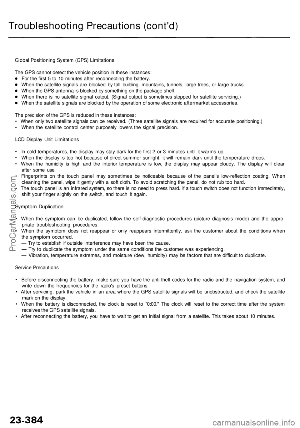
Global Positionin g Syste m (GPS ) Limitation s
Th e GP S canno t detec t th e vehicl e positio n in thes e instances :
Fo r th e firs t 5 to 1 0 minute s afte r reconnectin g th e battery .
Whe n th e satellit e signal s ar e blocke d b y tal l building , mountains , tunnels , larg e trees , o r larg e trucks .
Whe n th e GP S antenn a is blocke d b y somethin g o n th e packag e shelf .
Whe n ther e i s n o satellit e signa l output . (Signa l outpu t i s sometime s stoppe d fo r satellit e servicing. )
Whe n th e satellit e signal s ar e blocke d b y th e operatio n o f som e electroni c aftermarke t accessories .
Th e precisio n o f th e GP S is reduce d in thes e instances :
• Whe n onl y tw o satellit e signal s ca n b e received . (Thre e satellit e signal s ar e require d fo r accurat e positioning. )
• Whe n th e satellit e contro l cente r purposel y lower s th e signa l precision .
LC D Displa y Uni t Limitation s
• I n col d temperatures , th e displa y ma y sta y dar k fo r th e firs t 2 o r 3 minute s unti l i t warm s up .
• Whe n th e displa y i s to o ho t becaus e o f direc t summe r sunlight , i t wil l remai n dar k unti l th e temperatur e drops .
• Whe n th e humidit y i s hig h an d th e interio r temperatur e i s low , th e displa y ma y appea r cloudy . Th e displa y wil l clea r
afte r som e use .
• Fingerprint s o n th e touc h pane l ma y sometime s b e noticeabl e becaus e o f th e panel' s low-reflectio n coating . Whe n
cleanin g th e panel , wip e i t gentl y wit h a sof t cloth . T o avoi d scratchin g th e panel , d o no t ru b to o hard .
• Th e touc h pane l i s a n infrare d system , s o ther e is n o nee d t o pres s hard . I f a touc h switc h doe s no t functio n immediately ,
shif t you r finge r slightl y o n th e switch , an d touc h i t again .
Sympto m Duplicatio n
• Whe n th e sympto m ca n b e duplicated , follo w th e self-diagnosti c procedure s (pictur e diagnosi s mode ) an d th e appro -
priat e troubleshootin g procedures .
• Whe n th e sympto m doe s no t reappea r o r onl y reappear s intermittently , as k th e custome r abou t th e condition s whe n
th e sympto m occurred .
— Tr y t o establis h i f outsid e interferenc e ma y hav e bee n th e cause .
— Tr y t o duplicat e th e sympto m unde r th e sam e condition s th e custome r wa s experiencing .
— Vibration , temperatur e extremes , an d moistur e (dew , humidity ) ma y b e factor s tha t ar e difficul t t o duplicate .
Service Precaution s
• Befor e disconnectin g th e battery , mak e sur e yo u hav e th e anti-thef t code s fo r th e radi o an d th e navigatio n system , an d
writ e dow n th e frequencie s fo r th e radio' s prese t buttons .
• Afte r servicing , par k th e vehicl e i n a n are a wher e th e GP S satellit e signal s wil l b e unobstructed , an d chec k th e satellit e
mar k o n th e display .
• Whe n th e batter y i s disconnected , th e cloc k i s rese t t o "0:00. " Th e cloc k wil l rese t t o th e correc t tim e afte r th e syste m
receive s th e GP S satellit e signals .
• Afte r reconnectin g th e battery , yo u hav e t o wai t t o ge t a n initia l signa l fro m a satellite . Thi s take s abou t 1 0 minutes .
ProCarManuals.com
Page 1762 of 1954
Troubleshooting
'96 - 9 9 Model s (cont'd )
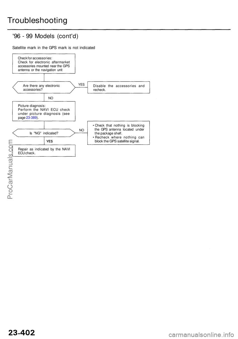
Satellite mar k i n th e GP S mar k is no t indicate d
Check fo r accessories :
Chec k fo r electroni c aftermarke t
accessorie s mounte d nea r th e GP S
antenn a o r th e navigatio n uni t
Disable th e accessorie s an d
recheck .Are ther e an y electroni caccessories ?
NO
YE S
Pictur e diagnosis :
Perfor m th e NAV I EC U chec k
under pictur e diagnosi s (se epage 23-389 ).
I s "NG " indicated ?
NO
• Chec k tha t nothin g i s blockin g
th e GP S antenn a locate d unde r
th e packag e shelf .
• Rechec k wher e nothin g ca n
block th e GP S satellit e signal .
Repair a s indicate d b y th e NAV I
EC U check .
ProCarManuals.com
Page 1768 of 1954
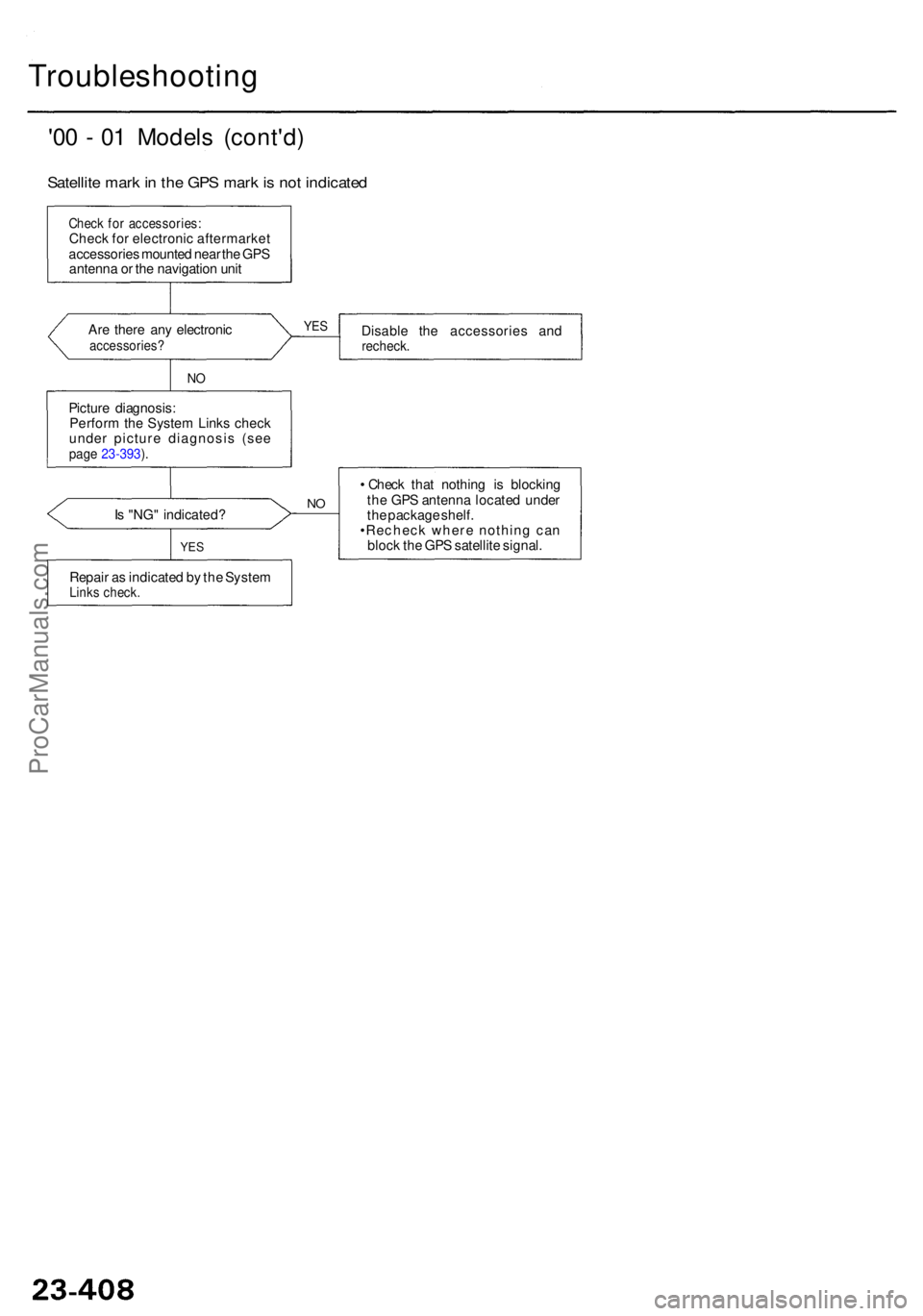
Troubleshooting
'00 - 0 1 Model s (cont'd )
Satellite mar k in th e GP S mar k is no t indicate d
Check fo r accessories :Check fo r electroni c aftermarke t
accessorie s mounte d nea r th e GP S
antenn a o r th e navigatio n uni t
Ar e ther e an y electroni c
accessories ?Disable th e accessorie s an drecheck .
YES
NO
Pictur e diagnosis :
Perfor m th e Syste m Link s chec k
unde r pictur e diagnosi s (se e
page 23-393 ).
• Chec k tha t nothin g i s blockin g
th e GP S antenn a locate d unde r
th e packag e shelf .
•Rechec k wher e nothin g ca n
bloc k th e GP S satellit e signal .
NOIs "NG " indicated ?
Repai r a s indicate d b y th e Syste m
Links check .
YES
ProCarManuals.com
Page 1777 of 1954
Clock Displa y Siz e an d Locatio n Adjustmen t
'00 - 0 1 model s onl y
1. Tur n th e ignitio n switc h O N (II) .
2 . Whe n th e disclaime r i s show n o n th e navigatio n displa y unit , touc h "OK. "
3 . Whe n th e "Ente r destinatio n by: " scree n i s shown , touc h "Setup. "
4 . Whe n th e "Setu p Screen " i s shown , touc h Displa y "Off. "
5 . Touc h th e number s o f th e cloc k t o chang e th e cloc k siz e an d location .
• I f th e cloc k i s smal l an d i n th e lowe r righ t han d come r o f th e screen , i t wil l increas e in siz e an d mov e t o th e cente r o f
th e screen .
• I f th e cloc k i s larg e an d i n th e cente r o f th e screen , i t wil l decreas e i n siz e an d mov e t o th e lowe r righ t han d corne r o f
th e screen .
6 . Pus h th e MEN U butto n t o retur n t o th e "Ente r destinatio n by: " screen .
The cloc k displa y setting s wil l b e saved .
ProCarManuals.com
Page 1779 of 1954
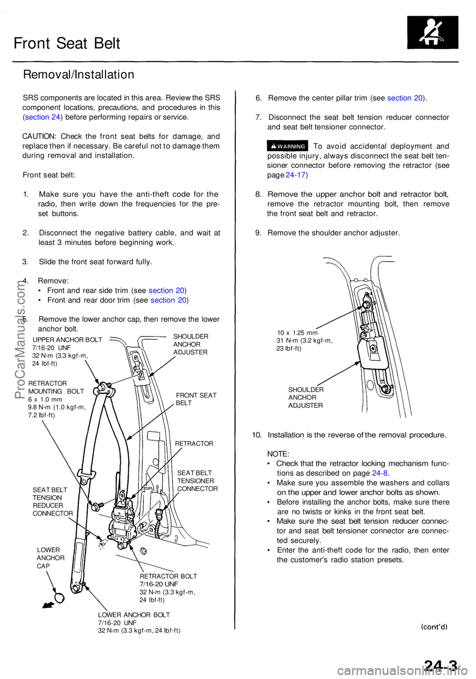
Front Sea t Bel t
Removal/Installatio n
SRS component s ar e locate d in thi s area . Revie w th e SR S
componen t locations , precautions , an d procedure s i n thi s
( sectio n 24 ) befor e performin g repair s o r service .
CAUTION : Chec k th e fron t sea t belt s fo r damage , an d
replac e the n if necessary . B e carefu l no t t o damag e the m
durin g remova l an d installation .
Fron t sea t belt :
1. Mak e sur e yo u hav e th e anti-thef t cod e fo r th e
radio , the n writ e dow n th e frequencie s fo r th e pre -
se t buttons .
2 . Disconnec t th e negativ e batter y cable , an d wai t a t
leas t 3 minute s befor e beginnin g work .
3 . Slid e th e fron t sea t forwar d fully .
4 . Remove :
• Fron t an d rea r sid e tri m (se e sectio n 20 )
• Fron t an d rea r doo r tri m (se e sectio n 20 )
5 . Remov e th e lowe r ancho r cap , the n remov e th e lowe r
ancho r bolt .
SHOULDE R
ANCHO R
ADJUSTE R
UPPER ANCHO R BOL T
7/16-2 0 UN F
3 2 N- m (3. 3 kgf-m ,
24 Ibf-ft )
RETRACTO RMOUNTING BOL T6 x 1. 0 m m9.8 N- m (1. 0 kgf-m ,
7. 2 Ibf-ft )
SEA T BEL T
TENSIO NREDUCE RCONNECTO R
LOWERANCHO RCAP
FRON T SEA TBELT
RETRACTO R
SEAT BEL T
TENSIONE R
CONNECTO R
RETRACTOR BOL T7/16-2 0 UN F32 N- m (3. 3 kgf-m ,24 Ibf-ft )
LOWE R ANCHO R BOL T
7/16-2 0 UN F
3 2 N- m (3. 3 kgf-m , 2 4 Ibf-ft )
6. Remov e th e cente r pilla r tri m (se e sectio n 20 ).
7 . Disconnec t th e sea t bel t tensio n reduce r connecto r
an d sea t bel t tensione r connector .
T o avoi d accidenta l deploymen t an d
possibl e injury , alway s disconnec t th e sea t bel t ten -
sione r connecto r befor e removin g th e retracto r (se e
pag e 24-17 )
8. Remov e th e uppe r ancho r bol t an d retracto r bolt ,
remov e th e retracto r mountin g bolt , the n remov e
th e fron t sea t bel t an d retractor .
9 . Remov e th e shoulde r ancho r adjuster .
10 x 1.2 5 mm31 N- m (3. 2 kgf-m ,
2 3 Ibf-ft )
SHOULDE R
ANCHO R
ADJUSTE R
10. Installatio n is th e revers e o f th e remova l procedure .
NOTE:
• Chec k tha t th e retracto r lockin g mechanis m func -
tions a s described on pag e 24-8 .
• Mak e sur e yo u assembl e th e washer s an d collar s
on th e uppe r an d lowe r ancho r bolt s a s shown .
• Befor e installin g th e ancho r bolts , mak e sur e ther e
ar e n o twist s o r kink s i n th e fron t sea t belt .
• Mak e sur e th e sea t bel t tensio n reduce r connec -
tor an d sea t bel t tensione r connecto r ar e connec -
te d securely .
• Ente r th e anti-thef t cod e fo r th e radio , the n ente r
th e customer' s radi o statio n presets .
ProCarManuals.com
Page 1783 of 1954
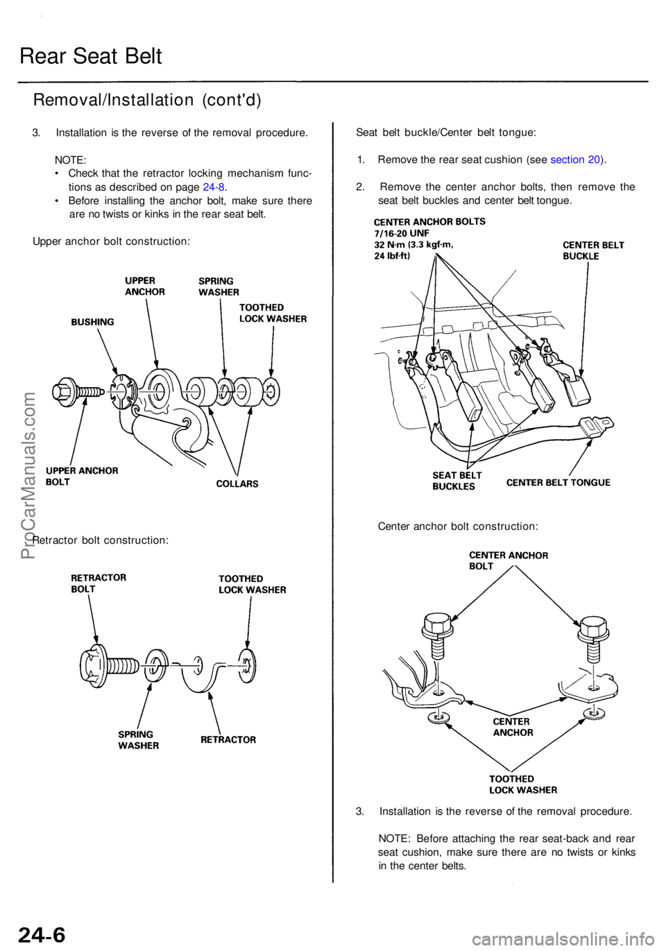
Rear Sea t Bel t
Removal/Installatio n (cont'd )
3. Installatio n i s th e revers e o f th e remova l procedure .
NOTE :
• Chec k tha t th e retracto r lockin g mechanis m func -
tion s a s describe d o n pag e 24-8 .
• Befor e installin g th e ancho r bolt , mak e sur e ther e
ar e n o twist s o r kink s i n th e rea r sea t belt .
Uppe r ancho r bol t construction :
Retracto r bol t construction : Sea
t bel t buckle/Cente r bel t tongue :
1 . Remov e th e rea r sea t cushio n (se e sectio n 20 ).
2 . Remov e th e cente r ancho r bolts , the n remov e th e
sea t bel t buckle s an d cente r bel t tongue .
3 . Installatio n i s th e revers e o f th e remova l procedure .
NOTE : Befor e attachin g th e rea r seat-bac k an d rea r
sea t cushion , mak e sur e ther e ar e n o twist s o r kink s
i n th e cente r belts .
Cente
r ancho r bol t construction :
ProCarManuals.com