1996 ACURA RL KA9 lock
[x] Cancel search: lockPage 1685 of 1954
Power Doo r Lock s
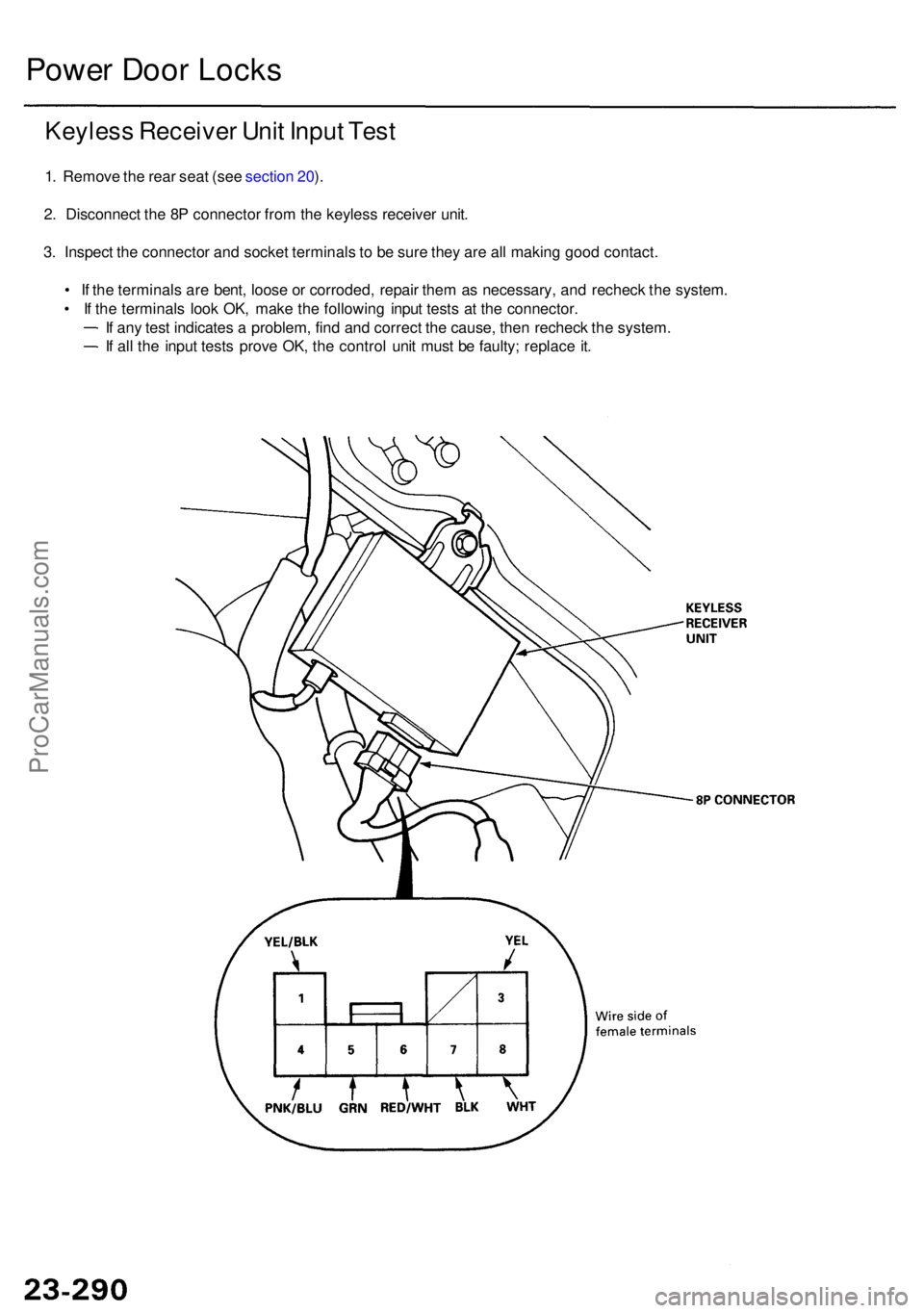
Keyles s Receive r Uni t Inpu t Tes t
1. Remov e th e rea r sea t (se e sectio n 20 ).
2 . Disconnec t th e 8 P connecto r fro m th e keyles s receive r unit .
3 . Inspec t th e connecto r an d socke t terminal s t o b e sur e the y ar e al l makin g goo d contact .
• I f th e terminal s ar e bent , loos e o r corroded , repai r the m a s necessary , an d rechec k th e system .
• I f th e terminal s loo k OK , mak e th e followin g inpu t test s a t th e connector .
I f an y tes t indicate s a problem , fin d an d correc t th e cause , the n rechec k th e system .
I f al l th e inpu t test s prov e OK , th e contro l uni t mus t b e faulty ; replac e it .
ProCarManuals.com
Page 1687 of 1954
Power Doo r Lock s
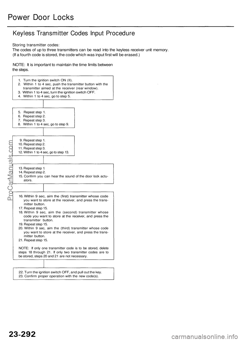
Keyles s Transmitte r Code s Inpu t Procedur e
Storing transmitte r codes :
The code s o f u p to thre e transmitter s ca n b e rea d int o th e keyles s receive r uni t memory .
(I f a fourt h cod e is stored , th e cod e whic h wa s inpu t firs t wil l b e erased. )
NOTE : I t i s importan t t o maintai n th e tim e limit s betwee n
th e steps .
1. Tur n th e ignitio n switc h O N (II) .
2 . Withi n 1 to 4 sec , pus h th e transmitte r butto n wit h th e
transmitte r aime d a t th e receive r (rea r window) .
3. Withi n 1 to 4 sec , tur n th e ignitio n switc h OFF .4. Withi n 1 to 4 sec , g o to ste p 5 .
5 . Repea t ste p 1 .
6 . Repea t ste p 2 .
7 . Repea t ste p 3 .
8 . Withi n 1 to 4 sec , g o to ste p 9 .
9 . Repea t ste p 1 .
10 . Repea t ste p 2 .
11 . Repea t ste p 3 .
12 . Withi n 1 to 4 sec , g o to ste p 13 .
13 . Repea t ste p 1.
14 . Repea t ste p 2 .
15 . Confir m yo u ca n hea r th e soun d o f th e doo r loc k actu -
ators .
16. Withi n 9 sec , ai m th e (first ) transmitte r whos e cod eyou wan t t o stor e a t th e receiver , an d pres s th e trans -mitter button .17. Repea t ste p 15 .
18 . Withi n 9 sec , ai m th e (second ) transmitte r whos e
code yo u wan t t o stor e a t th e receiver , an d pres s th etransmitte r button .
19 . Repea t ste p 15 .
20 . Withi n 9 sec , ai m th e (third ) transmitte r whos e cod e
yo u wan t t o stor e a t th e receiver , an d pres s th e trans -
mitter button .21. Repea t ste p 15 .
NOTE : I f onl y on e transmitte r cod e i s t o b e stored , delet e
step s 1 8 throug h 21 . I f onl y tw o transmitte r code s ar e t o
b e stored , step s 2 0 an d 2 1 ar e no t necessary .
22. Tur n th e ignitio n switc h OFF , an d pul l ou t th e key .23. Confir m prope r operatio n wit h th e ne w code(s) .
ProCarManuals.com
Page 1689 of 1954
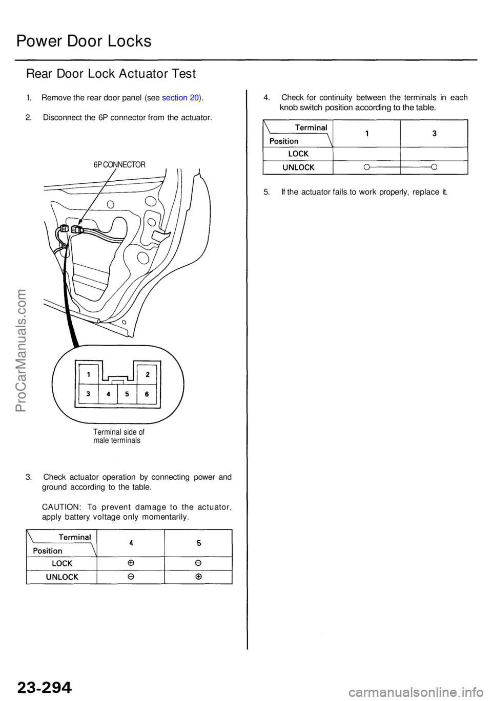
3. Chec k actuato r operatio n b y connectin g powe r an d
groun d accordin g t o th e table .
CAUTION : T o preven t damag e t o th e actuator ,
appl y batter y voltag e onl y momentarily .
Terminal sid e o f
mal e terminal s
Power Doo r Lock s
Rear Doo r Loc k Actuato r Tes t
1. Remov e th e rea r doo r pane l (se e sectio n 20 ).
2 . Disconnec t th e 6 P connecto r fro m th e actuator .
6P CONNECTO R
4. Chec k fo r continuit y betwee n th e terminal s i n eac h
knob switc h positio n accordin g to th e table .
5. I f th e actuato r fail s t o wor k properly , replac e it .
ProCarManuals.com
Page 1707 of 1954
Wiper/Washer
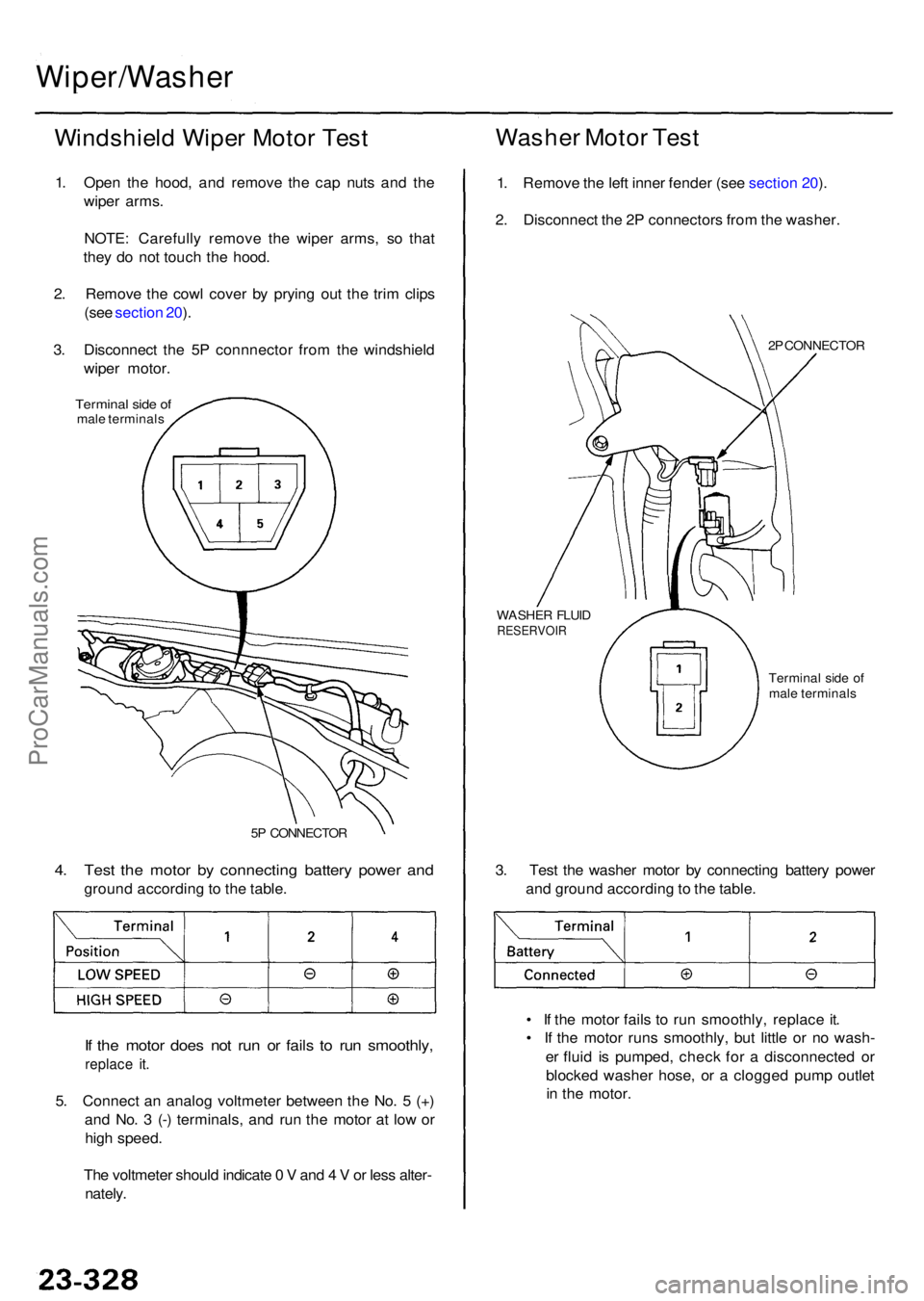
Windshield Wipe r Moto r Tes t
1. Ope n th e hood , an d remov e th e ca p nut s an d th e
wipe r arms .
NOTE : Carefull y remov e th e wipe r arms , s o tha t
the y d o no t touc h th e hood .
2 . Remov e th e cow l cove r b y pryin g ou t th e tri m clip s
(se e sectio n 20 ).
3 . Disconnec t th e 5 P connnecto r fro m th e windshiel d
wipe r motor .
Termina l sid e o fmal e terminal s
Washer Moto r Tes t
1. Remov e th e lef t inne r fende r (se e sectio n 20 ).
2 . Disconnec t th e 2 P connector s fro m th e washer .
2P CONNECTO R
WASHE R FLUI D
RESERVOI R
Terminal sid e o f
mal e terminal s
3. Tes t th e washe r moto r b y connectin g batter y powe r
an d groun d accordin g to th e table .
• I f th e moto r fail s t o ru n smoothly , replac e it .
• I f th e moto r run s smoothly , bu t littl e o r n o wash -
e r flui d i s pumped , chec k fo r a disconnecte d o r
blocke d washe r hose , o r a clogge d pum p outle t
i n th e motor .4. Tes t th e moto r b y connectin g batter y powe r an d
groun d accordin g to th e table .
5P CONNECTO R
If th e moto r doe s no t ru n o r fail s t o ru n smoothly ,
replace it .
5. Connec t a n analo g voltmete r betwee n th e No . 5 (+ )
an d No . 3 (- ) terminals , an d ru n th e moto r a t lo w o r
hig h speed .
Th e voltmete r shoul d indicat e 0 V and 4 V or les s alter -
nately .
ProCarManuals.com
Page 1711 of 1954
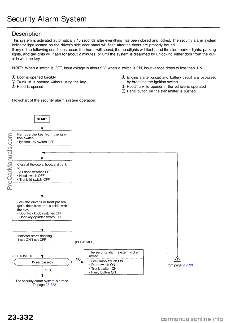
Indicator start s flashin g1 se c ON/ 1 sec OF F
15 se c passed ?
The securit y alar m syste m is armed .
T o pag e 23-333
YE S
The securit y alar m syste m is dis -
arme d
• Loc k kno b switc h O N
• Doo r switc h O N
• Trun k switc h O N
• Pani c butto n O N
Loc
k th e driver' s o r fron t passen -
ger' s doo r fro m th e outsid e wit h
the key .• Doo r loc k kno b switche s OF F• Doo r ke y cylinde r switc h OF F
From pag e 23-333
Securit y Alar m Syste m
Descriptio n
This syste m is activate d automaticall y 1 5 second s afte r everythin g ha s bee n close d an d locked . Th e securit y alar m syste m
indicato r ligh t locate d o n th e driver' s sid e doo r pane l wil l flas h afte r th e door s ar e properl y locked .
If an y o f th e followin g condition s occur , th e horn s wil l sound , th e headlight s wil l flash , an d th e sid e marke r lights , parkin g
lights, an d taillight s wil l flas h fo r abou t 2 minutes , o r unti l th e syste m is disarme d b y unlockin g eithe r doo r fro m th e out -
side wit h th e key .
NOTE : Whe n a switc h is OFF , inpu t voltag e is abou t 5 V . whe n a switc h is ON , inpu t voltag e drop s t o les s tha n 1 V .
Doo r i s opene d forcibly
Trun k li d i s opene d withou t usin g th e ke y
Hoo d i s opene d
Flowchar t o f th e securit y alar m syste m operation : Engin
e starte r circui t an d batter y circui t ar e bypasse d
by breakin g th e ignitio n switc h
Hood/trun k li d opene r i n th e vehicl e i s operate d
Pani c butto n o n th e transmitte r i s pushe d
Remov e th e ke y fro m th e igni -
tio n switc h
• Ignitio n ke y switc h OF F
Clos e al l th e doors , hood , an d trun klid.• Al l doo r switche s OF F
• Hoo d switc h OF F
• Trun k li d switc h OF F
(PREARMED )
(PREARMED)NO
ProCarManuals.com
Page 1712 of 1954
![ACURA RL KA9 1996 Service Repair Manual From pag e 23-332
Indicato r flashe s
0.2 se c ON/2. 4 se c OF F(ARMED )
YES
Wan t th e syste m disarmed ?
• Trun k li d switc h O N
• Trun k ke y cylinde r switc h O N[UNLOCK ]
Trunk opene d wit ACURA RL KA9 1996 Service Repair Manual From pag e 23-332
Indicato r flashe s
0.2 se c ON/2. 4 se c OF F(ARMED )
YES
Wan t th e syste m disarmed ?
• Trun k li d switc h O N
• Trun k ke y cylinde r switc h O N[UNLOCK ]
Trunk opene d wit](/manual-img/32/56992/w960_56992-1711.png)
From pag e 23-332
Indicato r flashe s
0.2 se c ON/2. 4 se c OF F(ARMED )
YES
Wan t th e syste m disarmed ?
• Trun k li d switc h O N
• Trun k ke y cylinde r switc h O N[UNLOCK ]
Trunk opene d wit h key ?YES
NO
N O
Illega l activit y (An y o f th e following )
1. Doo r i s opene d forcibl y o r
2 . Trun k li d is opene d withou t usin g th e ke y o r
3 . Hoo d is opene d o r
4 . Batter y terminal(s ) ar e disconnecte d an d
reconnecte d o r5. Engin e starte r circui t an d batter y circui t ar e
bypasse d b y breakin g th e ignitio n switc h o r
6 . Hood/trun k li d opene r i n th e vehicl e is
operate d o r
7. Pani c butto n is pushe d
• Th e horns , headlights , sid e marke r lights , an d tail -
light s soun d an d flas h repeatedl y fo r tw o minutes .
• Engin e starte r circui t interrupte d
Abou t 2 minute s passed ?
YESNOWan t th e syste m disarmed ?
YES
Eithe r doo r unlocke d b y usin g
th e ke y o r transmitte r
• Eithe r doo r ke y cylinde r switc h
ON [UNLOCK ]
The securit y alar m syste m isdisarme d
Indicato r stop s flashin g
Rear m th e securit y alar m system ?
NOYE S
To pag e 23-332
ProCarManuals.com
Page 1714 of 1954
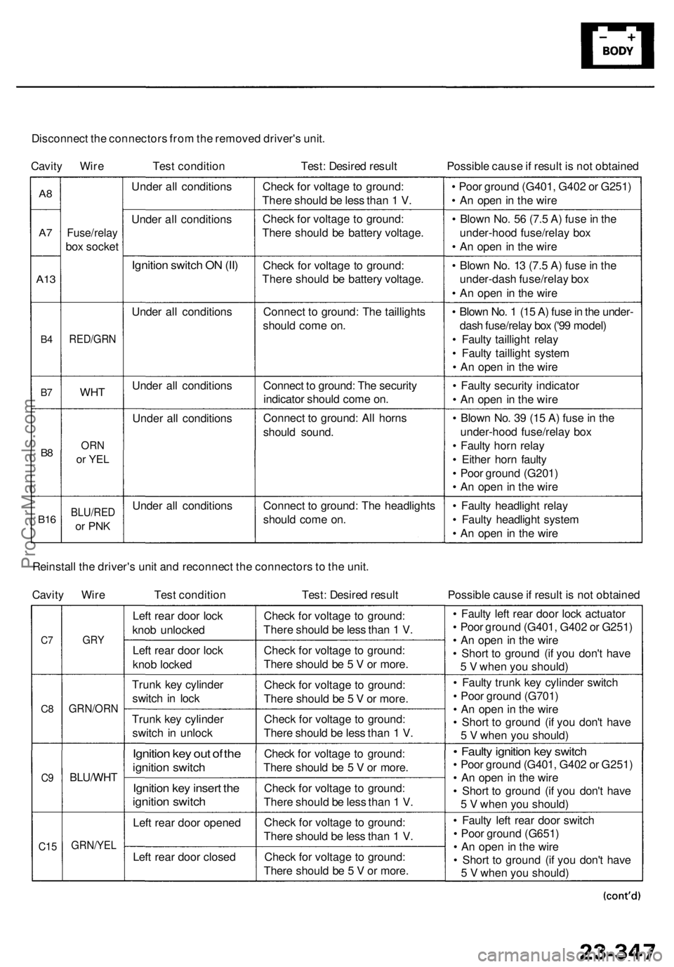
Disconnect th e connector s fro m th e remove d driver' s unit .
Cavit y Wir e Test conditio n Test: Desire d resul t Possible caus e if resul t i s no t obtaine d
A8
A7
A1 3
B4
B7
B8
B1 6
Fuse/rela y
box socke t
RED/GR N
WHT
ORN
or YE L
BLU/RE D
or PN K
Unde r al l condition s
Unde r al l condition s
Ignition switc h O N (II )
Unde r al l condition s
Unde r al l condition s
Unde r al l condition s
Unde r al l condition sChec
k fo r voltag e t o ground :
Ther e shoul d b e les s tha n 1 V .
Chec k fo r voltag e t o ground :
Ther e shoul d b e batter y voltage .
Chec k fo r voltag e t o ground :
Ther e shoul d b e batter y voltage .
Connec t t o ground : Th e taillight s
shoul d com e on .
Connec t t o ground : Th e securit y
indicato r shoul d com e on .
Connec t t o ground : Al l horn s
shoul d sound .
Connec t t o ground : Th e headlight s
shoul d com e on . •
Poo r groun d (G401 , G40 2 o r G251 )
• A n ope n in th e wir e
• Blow n No . 5 6 (7. 5 A ) fus e in th e
under-hoo d fuse/rela y bo x
• A n ope n in th e wir e
• Blow n No . 1 3 (7. 5 A ) fus e in th e
under-das h fuse/rela y bo x
• A n ope n in th e wir e
• Blow n No . 1 (1 5 A ) fus e in th e under -
das h fuse/rela y bo x ('9 9 model )
• Fault y tailligh t rela y
• Fault y tailligh t syste m
• A n ope n in th e wir e
• Fault y securit y indicato r
• A n ope n in th e wir e
• Blow n No . 3 9 (1 5 A ) fus e in th e
under-hoo d fuse/rela y bo x
• Fault y hor n rela y
• Eithe r hor n fault y
• Poo r groun d (G201 )
• A n ope n in th e wir e
• Fault y headligh t rela y
• Fault y headligh t syste m
• A n ope n in th e wir e
Reinstal l th e driver' s uni t an d reconnec t th e connector s to th e unit .
Cavit y Wir e Test conditio n Test: Desire d resul t Possible caus e if resul t i s no t obtaine d
C7
C 8
C9
C1 5
GR Y
GRN/OR N
BLU/WHT
GRN/YE L
Left rea r doo r loc k
kno b unlocke d
Lef t rea r doo r loc k
kno b locke d
Trun k ke y cylinde r
switc h i n loc k
Trun k ke y cylinde r
switc h i n unloc k
Ignition ke y ou t o f th e
ignitio n switc h
Ignitio n ke y inser t th e
ignitio n switc h
Left rea r doo r opene d
Lef t rea r doo r close d Chec
k fo r voltag e t o ground :
Ther e shoul d b e les s tha n 1 V .
Chec k fo r voltag e t o ground :
Ther e shoul d b e 5 V or more .
Chec k fo r voltag e t o ground :
Ther e shoul d b e 5 V or more .
Chec k fo r voltag e t o ground :
Ther e shoul d b e les s tha n 1 V .
Chec k fo r voltag e t o ground :
Ther e shoul d b e 5 V or more .
Chec k fo r voltag e t o ground :
Ther e shoul d b e les s tha n 1 V .
Chec k fo r voltag e t o ground :
Ther e shoul d b e les s tha n 1 V .
Chec k fo r voltag e t o ground :
Ther e shoul d b e 5 V or more . •
Fault y lef t rea r doo r loc k actuato r
• Poo r groun d (G401 , G40 2 o r G251 )
• A n ope n i n th e wir e
• Shor t t o groun d (i f yo u don' t hav e
5 V whe n yo u should )
• Fault y trun k ke y cylinde r switc h
• Poo r groun d (G701 )
• A n ope n in th e wir e
• Shor t t o groun d (i f yo u don' t hav e
5 V whe n yo u should )
• Fault y ignitio n ke y switc h
• Poo r groun d (G401 , G40 2 o r G251 )
• A n ope n in th e wir e
• Shor t t o groun d (i f yo u don' t hav e
5 V whe n yo u should )
• Fault y lef t rea r doo r switc h
• Poo r groun d (G651 )
• A n ope n in th e wir e
• Shor t t o groun d (i f yo u don' t hav e
5 V whe n yo u should )
ProCarManuals.com
Page 1716 of 1954
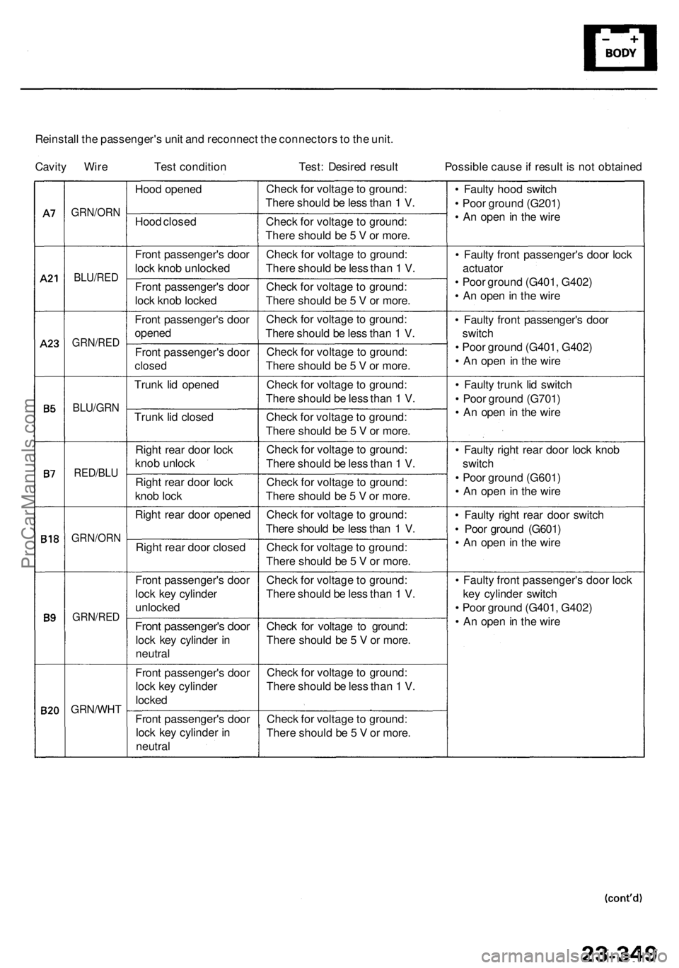
Reinstall th e passenger' s uni t an d reconnec t th e connector s to th e unit .
Cavit y Wir e Tes t conditio n Test : Desire d resul t Possibl e caus e if resul t i s no t obtaine d
• Fault y hoo d switc h
• Poo r groun d (G201 )
• A n ope n in th e wir e
• Fault y fron t passenger' s doo r loc k
actuato r
• Poo r groun d (G401 , G402 )
• A n ope n in th e wir e
• Fault y fron t passenger' s doo r
switc h
• Poo r groun d (G401 , G402 )
• A n ope n i n th e wir e
• Fault y trun k li d switc h
• Poo r groun d (G701 )
• A n ope n in th e wir e
• Fault y righ t rea r doo r loc k kno b
switc h
• Poo r groun d (G601 )
• A n ope n in th e wir e
• Fault y righ t rea r doo r switc h
• Poo r groun d (G601 )
• A n ope n in th e wir e
• Fault y fron t passenger' s doo r loc k
ke y cylinde r switc h
• Poo r groun d (G401 , G402 )
• A n ope n in th e wir e
Chec
k fo r voltag e to ground :
Ther e shoul d b e les s tha n 1 V .
Chec k fo r voltag e to ground :
Ther e shoul d b e 5 V or more .
Chec k fo r voltag e t o ground :
Ther e shoul d b e les s tha n 1 V .
Chec k fo r voltag e to ground :
Ther e shoul d b e 5 V or more .
Chec k fo r voltag e to ground :
Ther e shoul d b e les s tha n 1 V .
Chec k fo r voltag e to ground :
Ther e shoul d b e 5 V or more .
Chec k fo r voltag e to ground :
Ther e shoul d b e les s tha n 1 V .
Chec k fo r voltag e to ground :
Ther e shoul d b e 5 V or more .
Chec k fo r voltag e to ground :
Ther e shoul d b e les s tha n 1 V .
Chec k fo r voltag e to ground :
Ther e shoul d b e 5 V or more .
Chec k fo r voltag e to ground :
Ther e shoul d b e les s tha n 1 V .
Chec k fo r voltag e to ground :
Ther e shoul d b e 5 V or more .
Chec k fo r voltag e to ground :
Ther e shoul d b e les s tha n 1 V .
Chec k fo r voltag e t o ground :
Ther e shoul d b e 5 V or more .
Chec k fo r voltag e to ground :
Ther e shoul d b e les s tha n 1 V .
Chec k fo r voltag e to ground :
Ther e shoul d b e 5 V or more .
Fron
t passenger' s doo r
loc k ke y cylinde r i n
neutra l
Fron
t passenger' s doo r
loc k ke y cylinde r
locked
Front passenger' s doo r
lock ke y cylinde r i n
neutra l
GRN/WH T
GRN/RED
Front passenger' s doo r
loc k ke y cylinde r
unlocke d
Right rea r doo r close d
Righ
t rea r doo r opene d
Righ
t rea r doo r loc k
kno b loc k
Righ
t rea r doo r loc k
kno b unloc k
Trun
k li d close d
Trun
k li d opene d
Fron
t passenger' s doo r
close d
Front passenger' s doo r
opene d
Fron
t passenger' s doo r
loc k kno b locke d
Fron
t passenger' s doo r
loc k kno b unlocke d
Hoo
d close d
Hoo
d opene d
GRN/OR N
BLU/RED
GRN/RE D
BLU/GRN
RED/BLU
GRN/OR N
ProCarManuals.com