Page 1784 of 1954
Center sea t belt/Cente r sea t bel t buckl e ('9 8 - 0 1 models) :
1 . Remove :
• Rea r sea t cushio n an d rea r seat-bac k (se e
section 20 )
• Rea r sid e tri m (se e sectio n 20 )
• Rea r doo r tri m (se e sectio n 20 )
• Rea r pilla r tri m pane l (se e sectio n 20 )
• Rea r shel f (se e sectio n 20 )
CENTE R SEA T BEL T
Lower/cente r ancho r bol t construction :
3 . Installatio n i s th e revers e o f th e remova l procedure .
NOTE:
• Chec k tha t th e retracto r lockin g mechanis m func -
tion s a s describe d o n pag e 24-8 .
• Befor e installin g th e ancho r bolt , mak e sur e
ther e ar e n o twist s o r kink s i n th e rea r cente r sea t
belt.
3. Remov e th e cente r sea t bel t ancho r bolt , the n
remov e th e cente r sea t bel t buckle .
ProCarManuals.com
Page 1786 of 1954

On-the Car Seat Belt Inspection
1. Check that the seat belt is not twisted or caught on
anything.
2. After installing the anchors, check for free move-
ment on the anchor bolts. If necessary, remove the
anchor bolts and check that the washers and other
parts are not damaged or improperly installed.
3. Check the seat belts for damage or discoloration.
Clean with a shop towel if necessary.
CAUTION: Use only soap and water to clean.
NOTE: Dirt build-up in the metal loops of the upper
anchors can cause the seat belts to retract slowly.
Wipe the inside of the loops with a clean cloth damp-
ened in isopropyl alcohol.
4. Check that the seat belt does not lock when pulled
out slowly. The seat belt is designed to lock only
during a sudden stop or impact.
5. Make sure that the seat belt will retract automatically
when released.
6. For each passenger's seat belt, make sure that the
locking mechanism in the seat belt retractor will
engage when the seat belt is pulled all the way out.
7. Replace the seat belt with a new assembly if there is
any abnormality. Do not disassemble any part of
the seat belt for any reason.ProCarManuals.com
Page 1797 of 1954

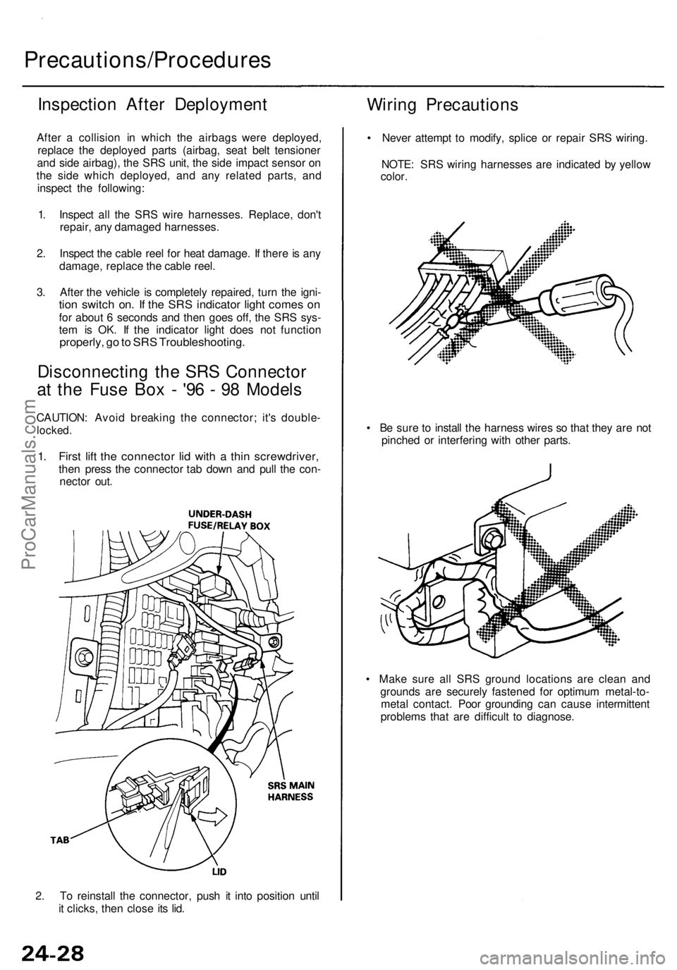
2. To reinstall the connector, push it into position until
it clicks, then close its lid.
Precautions/Procedures
Inspection After Deployment
After a collision in which the airbags were deployed,
replace the deployed parts (airbag, seat belt tensioner
and side airbag), the SRS unit, the side impact sensor on
the side which deployed, and any related parts, and
inspect the following:
1. Inspect all the SRS wire harnesses. Replace, don't
repair, any damaged harnesses.
2. Inspect the cable reel for heat damage. If there is any
damage, replace the cable reel.
3. After the vehicle is completely repaired, turn the igni-
tion switch on. If the SRS indicator light comes on
for about 6 seconds and then goes off, the SRS sys-
tem is OK. If the indicator light does not function
properly, go to SRS Troubleshooting.
Disconnecting the SRS Connector
at the Fuse Box - '96 - 98 Models
CAUTION: Avoid breaking the connector; it's double-
locked.
1. First lift the connector lid with a thin screwdriver,
then press the connector tab down and pull the con-
nector out.
Wiring Precautions
• Never attempt to modify, splice or repair SRS wiring.
NOTE: SRS wiring harnesses are indicated by yellow
color.
• Be sure to install the harness wires so that they are not
pinched or interfering with other parts.
• Make sure all SRS ground locations are clean and
grounds are securely fastened for optimum metal-to-
metal contact. Poor grounding can cause intermittent
problems that are difficult to diagnose.ProCarManuals.com
Page 1798 of 1954

Side Airbag Connector:
Disconnecting
To release the lock, pull the slider and the spring-loaded
sleeve while holding the opposite half of the connector.
Then pull the connector halves apart. Be sure to pull on
the sleeve and not on the connector half.
Spring-loaded Lock Connector
Some SRS system connectors have a spring-loaded lock.
Frontal Airbags and Seat Belt Tensioners:
Disconnecting
To release the lock, pull the spring-loaded sleeve toward
the stop while holding the opposite half of the connector.
Then pull the connector halves apart.
NOTE: Be sure to pull on the sleeve and not on the
connector half. SPRING-LOADED
SLEEVE
Connecting
1. Hold the pawl-side connector half, and press on the
back of the sleeve-side connector half in the direction
shown. As the two connector halves are pressed
together, the sleeve is pushed back by the pawl.
NOTE: Do not touch the sleeve.
2. When the connector halves are completely connected,
the pawl is released, and the spring-loaded sleeve
locks the connector.
SPRING-LOADED
SLEEVE
Connecting
Hold the both connector halves, and press them forcibly
until the projection of the sleeve-side connector clicks to
lock.ProCarManuals.com
Page 1800 of 1954

Backprobing Spring-loade d Loc k
Connector s
• Whe n checkin g voltag e o r resistanc e o n thi s typ e o f
connecto r th e firs t time , i t i s necessar y t o remov e th e
retaine r t o inser t teste r probe s fro m th e wir e side .
NOTE : I t i s no t necessar y t o reinstal l th e remove d
retainer ; th e terminal s wil l sta y locke d i n th e connec -
to r housing .
Disconnectin g th e Airba g
Connector s an d Sea t Bel t
Tensione r Connector s
'9 6 - 9 8 Model s
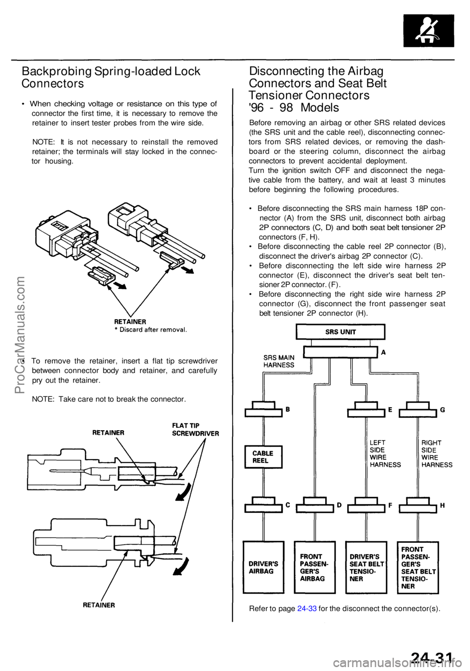
Before removin g a n airba g o r othe r SR S relate d device s
(th e SR S uni t an d th e cabl e reel) , disconnectin g connec -
tor s fro m SR S relate d devices , o r removin g th e dash -
boar d o r th e steerin g column , disconnec t th e airba g
connector s t o preven t accidenta l deployment .
Tur n th e ignitio n switc h OF F an d disconnec t th e nega -
tiv e cabl e fro m th e battery , an d wai t a t leas t 3 minute s
befor e beginnin g th e followin g procedures .
• Befor e disconnectin g th e SR S mai n harnes s 18 P con -
necto r (A ) fro m th e SR S unit , disconnec t bot h airba g
2P connector s (C , D ) an d bot h sea t bel t tensione r 2 P
connector s (F , H) .
• Befor e disconnectin g th e cabl e ree l 2 P connecto r (B) ,
disconnec t th e driver' s airba g 2 P connecto r (C) .
• Befor e disconnectin g th e lef t sid e wir e harnes s 2 P
connecto r (E) , disconnec t th e driver' s sea t bel t ten -
sione r 2 P connector . (F) .
• Befor e disconnectin g th e righ t sid e wir e harnes s 2 P
connecto r (G) , disconnec t th e fron t passenge r sea t
bel t tensione r 2 P connecto r (H) .
Refe r t o pag e 24-3 3 fo r th e disconnec t th e connector(s) .
•
T o remov e th e retainer , inser t a fla t ti p screwdrive r
betwee n connecto r bod y an d retainer , an d carefull y
pr y ou t th e retainer .
NOTE : Tak e car e no t t o brea k th e connector .
ProCarManuals.com
Page 1803 of 1954

Precautions/Procedures
Steering-related Precaution s
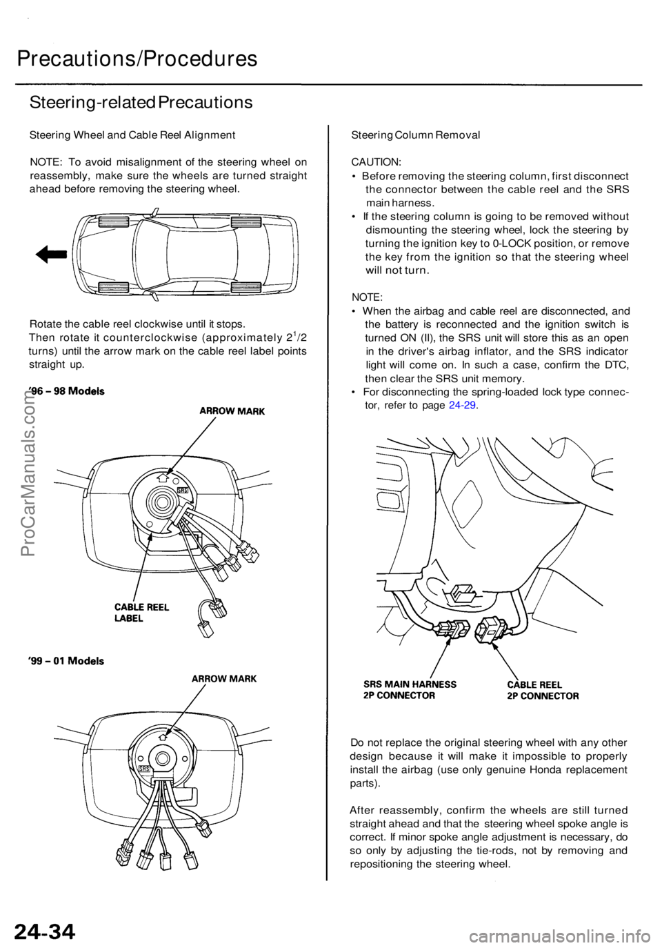
Steering Whee l an d Cabl e Ree l Alignmen t
NOTE : T o avoi d misalignmen t o f th e steerin g whee l o n
reassembly , mak e sur e th e wheel s ar e turne d straigh t
ahea d befor e removin g th e steerin g wheel .
Rotat e th e cabl e ree l clockwis e unti l i t stops .
The n rotat e i t counterclockwis e (approximatel y 2
1/2
turns ) unti l th e arro w mar k o n th e cabl e ree l labe l point s
straigh t up . Steerin
g Colum n Remova l
CAUTION :
• Befor e removin g th e steerin g column , firs t disconnec t
th e connecto r betwee n th e cabl e ree l an d th e SR S
mai n harness .
• I f th e steerin g colum n is goin g to b e remove d withou t
dismountin g th e steerin g wheel , loc k th e steerin g b y
turnin g th e ignitio n ke y to 0-LOC K position , o r remov e
th e ke y fro m th e ignitio n s o tha t th e steerin g whee l
will no t turn .
NOTE :
• Whe n th e airba g an d cabl e ree l ar e disconnected , an d
th e batter y i s reconnecte d an d th e ignitio n switc h i s
turne d O N (II) , th e SR S uni t wil l stor e thi s a s a n ope n
i n th e driver' s airba g inflator , an d th e SR S indicato r
ligh t wil l com e on . I n suc h a case , confir m th e DTC ,
the n clea r th e SR S uni t memory .
• Fo r disconnectin g th e spring-loade d loc k typ e connec -
tor, refe r t o pag e 24-29 .
Do no t replac e th e origina l steerin g whee l wit h an y othe r
desig n becaus e i t will mak e i t impossibl e t o properl y
instal l th e airba g (us e onl y genuin e Hond a replacemen t
parts).
After reassembly , confir m th e wheel s ar e stil l turne d
straigh t ahea d an d tha t th e steerin g whee l spok e angl e is
correct . I f mino r spok e angl e adjustmen t i s necessary , d o
s o onl y b y adjustin g th e tie-rods , no t b y removin g an d
repositionin g th e steerin g wheel .
ProCarManuals.com
Page 1950 of 1954
'99 - 01 Models
'99 - 01 Models
16. Install the steering wheel, then connect the radio
remote switch connector, horn connector and cruise
control set/resume/cancel switch connector.
'96 - 98 Models
14. Install the steering column covers.
15. If necessary, center the cable reel. (New replace-
ment cable reels come centered.) Do this by first
rotating the cable reel clockwise until it stops. Then
rotate it counterclockwise (about 21/2 turns) until the
arrow mark on the cable reel label points straight
up.
'96 - 98 Models
'99 - 01 ModelsProCarManuals.com