Page 888 of 1954
Transmission Rang e Switc h (A/ T Gea r Positio n
Switch)
Remova l
1. Shif t th e deten t leve r t o th e position .
TRANSMISSIO N
RANG E SWITC H
LOCKNU T
LOCK WASHE RReplace.
DETENTLEVER
CONTRO LSHAFT
2. Pr y th e locktab s o n th e loc k washer , the n remov e
the locknu t an d loc k washer .
3 . Remov e th e bolt s securin g th e transmissio n rang e
switch , the n remov e th e transmissio n rang e switch .
ProCarManuals.com
Page 890 of 1954
3. Instal l th e transmissio n rang e switc h o n th e contro l
shaft , the n instal l th e bolt s loosely .
TRANSMISSIO N
RAN GE SWITC H
CONTROL
SHAF T
6 x 1. 0 m mTighte n loosely .
4. Instal l a ne w loc k washe r o n th e transmissio n rang e
switch b y alignin g it s projecte d ti p wit h th e posi -
tio n mar k o n th e transmissio n rang e switc h a s
shown .
POSITIO NMARKTRANSMISSIO N RANG E
SWITC H
6 x 1. 0 m m12 N- m (1. 2 kgf-m ,
8. 7 Ibf-ft )
DETEN T
LEVER
LOCKNU T
1 2 N- m (1. 2 kgf-m ,
8. 7 Ibf-ft ) CONTRO
L
SHAF T
5. Tighte n th e locknu t whil e holdin g th e deten t leve r i n
th e position , the n ben d th e loc k tab s agains t th e
locknut .
6. Tighte n th e 6 m m bolt s to th e specifie d torque .
LOCK WASHE RReplace.
ProCarManuals.com
Page 891 of 1954
Transmission
Reassembly
NOTE:
• Coat all parts with ATF.
• Replace the following parts:
- O-rings
- Lock washers
- Gaskets
- Mainshaft and countershaft locknuts and conical disc springs
- Sealing washersProCarManuals.com
Page 895 of 1954

Transmission
Reassembly (cont'd )
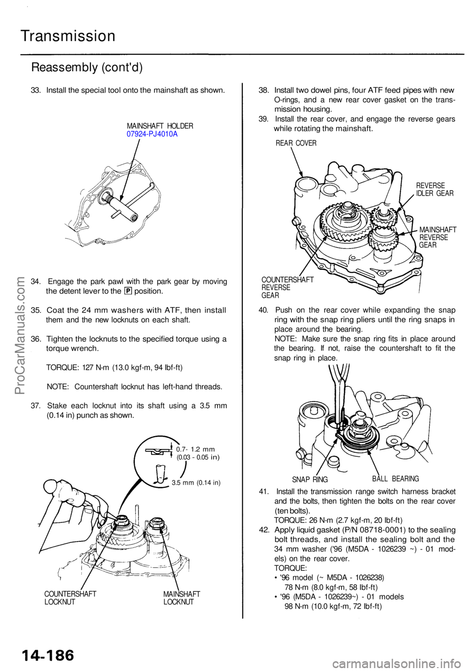
33. Instal l th e specia l too l ont o th e mainshaf t a s shown .
MAINSHAF T HOLDE R07924-PJ4010 A
34. Engag e th e par k paw l wit h th e par k gea r b y movin g
the deten t leve r t o th e position .
35. Coa t th e 2 4 m m washer s wit h ATF , the n instal l
them an d th e ne w locknut s o n eac h shaft .
36. Tighte n th e locknut s t o th e specifie d torqu e usin g a
torqu e wrench .
TORQUE : 12 7 N- m (13. 0 kgf-m , 9 4 Ibf-ft )
NOTE : Countershaf t locknu t ha s left-han d threads .
37 . Stak e eac h locknu t int o it s shaf t usin g a 3. 5 m m
(0.1 4 in ) punc h a s shown .
0.7- 1.2 m m(0.0 3 - 0.05 in)
3.5 m m (0.1 4 in )
COUNTERSHAF T
LOCKNU T MAINSHAF
T
LOCKNU T
38. Instal l tw o dowe l pins , fou r AT F fee d pipe s wit h ne w
O-rings , an d a ne w rea r cove r gaske t o n th e trans -
mission housing .
39. Instal l th e rea r cover , an d engag e th e revers e gear s
while rotatin g th e mainshaft .
REVERSE
IDLE R GEA R
MAINSHAF TREVERSE
GEA R
COUNTERSHAF TREVERSEGEAR
40. Pus h o n th e rea r cove r whil e expandin g th e sna p
ring wit h th e sna p rin g plier s unti l th e rin g snap s i n
plac e aroun d th e bearing .
NOTE : Mak e sur e th e sna p rin g fit s i n plac e aroun d
th e bearing . I f not , rais e th e countershaf t t o fi t th e
sna p rin g i n place .
SNAP RIN GBAL L BEARIN G
41. Instal l th e transmissio n rang e switc h harnes s bracke t
an d th e bolts , the n tighte n th e bolt s o n th e rea r cove r
(ten bolts) .
TORQUE : 2 6 N- m (2. 7 kgf-m , 2 0 Ibf-ft )
42. Appl y liqui d gaske t (P/ N 08718-0001 ) t o th e sealin g
bolt threads , an d instal l th e sealin g bol t an d th e
34 m m washe r ('9 6 (M5D A - 102623 9 ~ ) - 0 1 mod -
els ) o n th e rea r cover .
TORQUE :
• '9 6 mode l ( ~ M5D A - 1026238 )
7 8 N- m (8. 0 kgf-m , 5 8 Ibf-ft )
• '9 6 (M5D A - 1026239~ ) - 0 1 model s
9 8 N- m (10. 0 kgf-m , 7 2 Ibf-ft )
REAR COVE R
ProCarManuals.com
Page 901 of 1954

Transmission
Installation (cont'd )
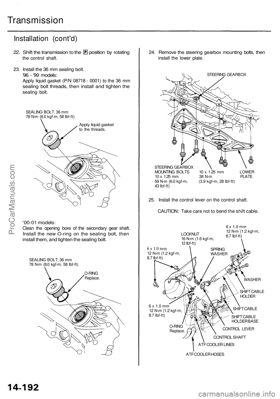
22. Shif t th e transmissio n to th e positio n b y rotatin g
the contro l shaft .
23. Instal l th e 3 6 m m sealin g bolt .
'96 - '9 9 models :
Apply liqui d gaske t (P/ N 0871 8 - 0001 ) t o th e 3 6 m m
sealin g bol t threads , the n instal l an d tighte n th e
sealin g bolt .
SEALIN G BOLT . 3 6 m m
7 8 N- m (8. 0 kgf-m , 5 8 Ibf-ft )
Apply liqui d gaske tto th e threads .
'00-01 models :
Clean th e openin g bor e o f th e secondar y gea r shaft .
Install th e ne w O-rin g o n th e sealin g bolt , the n
instal l them , an d tighte n th e sealin g bolt .
SEALIN G BOLT , 3 6 m m
7 8 N- m (8. 0 kgf-m , 5 8 Ibf-ft )
O-RIN G
Replace .
24. Remov e th e steerin g gearbo x mountin g bolts , the n
instal l th e lowe r plate .
STEERIN G GEARBO X
STEERIN G GEARBO X
MOUNTING BOLT S 1 0 x 1.2 5 m m LOWE R
1 0 x 1.2 5 m m 3 8 N- m PLAT E
5 9 N- m (6. 0 kgf-m , (3. 9 kgf-m , 2 8 Ibf-ft )
4 3 Ibf-ft )
25. Instal l th e contro l leve r o n th e contro l shaft .
CAUTION : Tak e car e no t t o ben d th e shif t cable .
6 x 1. 0 m m12 N- m (1. 2 kgf-m ,
8. 7 Ibf-ft )
WASHE R
LOCKNU T
1 6 N- m (1. 6 kgf-m ,
1 2 Ibf-ft )
SPRING
WASHE R
6 x 1. 0 m m12 N- m (1. 2 kgf-m ,
8. 7 Ibf-ft )
SHIFT CABL E
HOLDE R
SHIFT CABL E
SHIF T CABL E
HOLDE R BAS E
CONTRO L LEVE R
CONTRO L SHAF T
AT F COOLE R LINE S
O-RIN
G
Replace .
6 x 1. 0 m m12 N- m (1. 2 kgf-m ,
8. 7 Ibf-ft )
ATF COOLE R HOSE S
ProCarManuals.com
Page 905 of 1954

Transmission
Cooler Flushin g (cont'd )
17. Mak e sur e th e transmissio n is in th e position .
Then fil l th e transmissio n wit h ATF , an d ru n th e
engin e fo r 3 0 second s o r unti l approximatel y 0.9 5
(1. 0 U S qt. , 0. 8 Im p qt. ) i s discharged .
18 . Remov e th e drai n hose , an d reconnec t th e coole r
retur n hos e to th e transmissio n (se e nex t column) .
19 . Refil l th e transmissio n wit h th e recommende d AT F
t o th e prope r leve l (se e pag e 14-108 ).
TOO L MAINTENANC E
1 . Empt y an d rins e afte r eac h use . Fil l th e ca n wit h wate r
an d pressuriz e th e can . Flus h th e discharg e lin e t o
ensur e tha t th e uni t i s clean .
2 . I f discharg e liqui d doe s no t foam , th e orific e ma y b e
blocked .
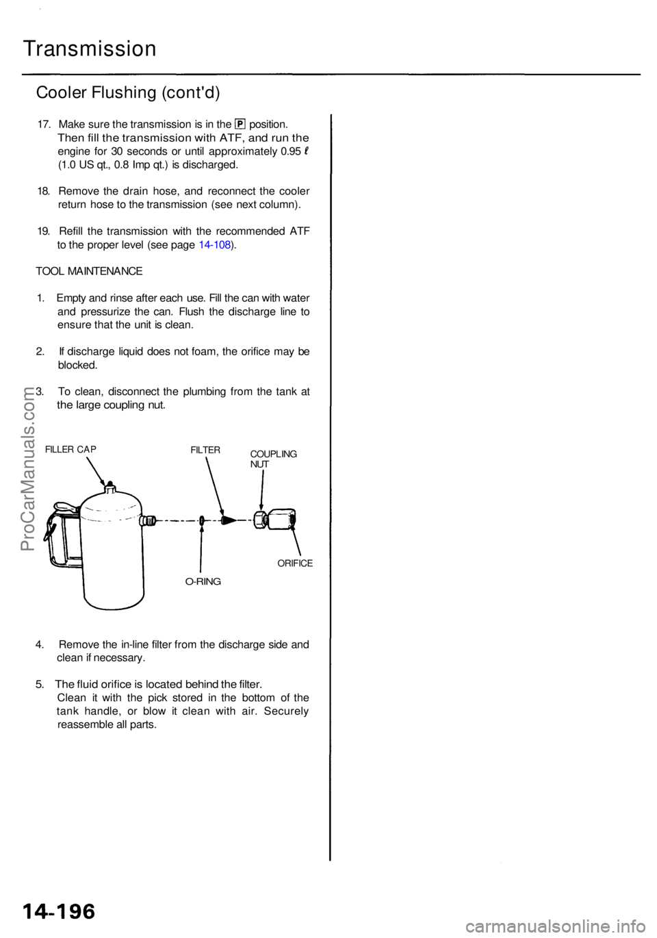
3 . T o clean , disconnec t th e plumbin g fro m th e tan k a t
the larg e couplin g nut .
FILLE R CA PFILTE RCOUPLIN GNUT
O-RIN G
ORIFIC E
4. Remov e th e in-lin e filte r fro m th e discharg e sid e an d
clea n if necessary .
5. Th e flui d orific e is locate d behin d th e filter .
Clea n i t wit h th e pic k store d i n th e botto m o f th e
tan k handle , o r blo w it clea n wit h air . Securel y
reassembl e al l parts .
ProCarManuals.com
Page 907 of 1954

Shift Leve r
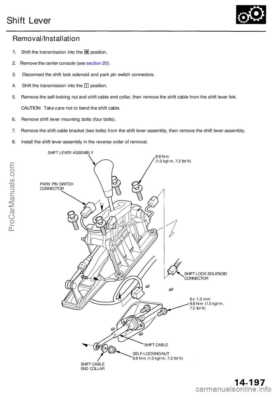
PARK PI N SWITC HCONNECTO R
SHIFT LOC K SOLENOI DCONNECTO R
6x 1. 0 m m9.8 N- m (1. 0 kgf-m ,7.2 Ibf-ft )
SHIFT CABL E
SELF-LOCKIN G NU T
9. 8 N- m (1. 0 kgf-m , 7.2 Ibf-ft )
SHIFT CABL EEND COLLA R
Removal/Installatio n
1. Shif t th e transmissio n int o th e [HI position .
2 . Remov e th e cente r consol e (se e sectio n 20 ).
3 . Disconnec t th e shif t loc k solenoi d an d par k pi n switc h connectors .
4. Shif t th e transmissio n int o th e Q] position .
5 . Remov e th e self-lockin g nu t an d shif t cabl e en d collar , the n remov e th e shif t cabl e fro m th e shif t leve r link .
CAUTION : Tak e car e no t t o ben d th e shif t cable .
6 . Remov e shif t leve r mountin g bolt s (fou r bolts) .
7 . Remov e th e shif t cabl e bracke t (tw o bolts ) fro m th e shif t leve r assembly , the n remov e th e shif t leve r assembly .
8 . Instal l th e shif t leve r assembl y in th e revers e orde r o f removal .
SHIFT LEVE R ASSEMBL Y6x 1.0m m,9.8 N- m(1.0 kgf-m , 7.2 Ibf-ft )
ProCarManuals.com
Page 908 of 1954
Shift Leve r
Disassembl y
SHIFT LOC K
RELEAS E LEVE R
LEVE R COVE R
SHIF T LOC K
STO P
6 x 1. 0 m m8 N- m (0. 8 kgf-m ,6 Ibf-ft)
SHIFT LEVE R KNO B
SHIF T LOC K SOLENOI D
6x 1. 0 m m8 N- m (0. 8 kgf-m , 6 Ibf-ft)
5 x 0. 8 m m4 N- m (0. 4 kgf-m , 3 Ibf-ft)
A/T GEA R POSITIO N
PANE L
COLLA R
RUBBE R
LOCK PI N
LIN K ADJUSTE R
LOCKNU T
7
N- m (0. 7 kgf-m , 5 Ibf-ft)
BRACKE T BAS E
PARK PI N SWITC H
CONTRO
L SEA L
ProCarManuals.com