1996 ACURA RL KA9 lock
[x] Cancel search: lockPage 759 of 1954

Troubleshooting Procedure s
Checking th e Diagnosti c Troubl e Cod e (DTC )
wit h a n OB D II Sca n Too l o r Hond a PG M Teste r
When th e PC M sense s a n abnormalit y i n th e inpu t o r outpu t systems , th e indicato r ligh t i n th e gaug e assembl y wil l
blink . Whe n th e 16 P Dat a Lin k Connecto r (DLC ) (locate d behin d th e ashtray ) i s connecte d to th e OB D II Sca n Too l o r Hond a
PG M Teste r a s shown , th e sca n too l o r teste r wil l indicat e th e Diagnosti c Troubl e Cod e (DTC ) whe n th e ignitio n switc h i s
turne d O N (II) .
If th e indicato r ligh t o r th e MI L ha s bee n reporte d on , o r i f a driveabilit y proble m is suspected , follo w thi s procedure :
1 . Connec t th e OB D II Sca n Too l (conformin g to SA E J1978 ) o r Hond a PG M Teste r t o th e 16 P DLC .
(Se e th e OB D II Sca n Too l o r Hond a PG M Teste r user' s manua l fo r specifi c instructions . I f yo u ar e usin g th e Hond a
PG M Tester , mak e sur e it i s se t t o th e SA E DT C type. )
2 . Tur n th e ignitio n switc h O N (II) , an d observ e th e DT C o n th e screen .
3 . Recor d al l fue l an d emission s DTCs , A/ T DTCs , an d freez e data .
4 . I f ther e is a fue l an d emission s DTC , firs t chec k th e fue l an d emission s syste m a s indicate d b y th e DT C (excep t fo r DT C
P0700) . DT C P070 0 mean s ther e is on e o r mor e A/ T DTC , an d n o problem s wer e detecte d in th e fue l an d emission s circui t
of th e PCM .
5. Ge t th e anti-thef t cod e fo r th e radio , the n writ e dow n th e radi o statio n presets .
6 . Rese t th e memor y wit h th e PG M Teste r o r b y removin g th e BAC K U P fus e i n th e under-hoo d fuse/rela y bo x fo r mor e
tha n 1 0 seconds .
7 . Driv e th e vehicl e fo r severa l minute s a t speed s ove r 3 0 mp h (5 0 km/h) , an d the n rechec k fo r DTCs . I f th e A/ T DT C
returns , g o t o th e Symptom-to-Componen t Char t (pag e 14-5 6 an d 14-57 ). I f th e DT C doe s no t return , ther e wa s a n inter -
mitten t proble m withi n th e circuit . Mak e sur e al l pin s an d terminal s i n th e circui t ar e tight , an d the n g o t o ste p 8 .
8 . Ente r th e anti-thef t cod e fo r th e radio , rese t th e radi o prese t stations , an d se t th e clock .
ProCarManuals.com
Page 765 of 1954
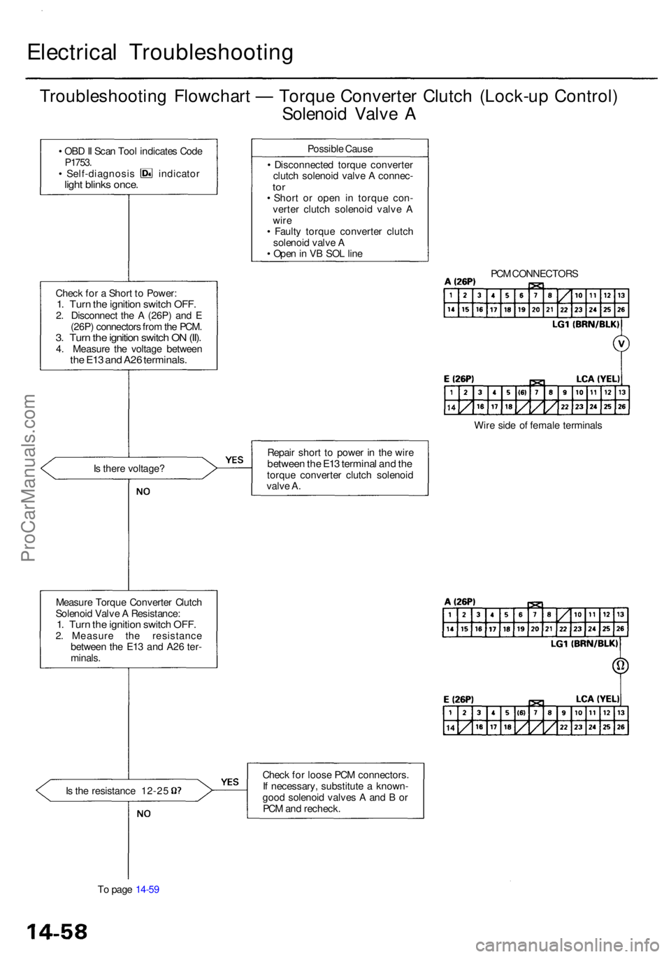
Electrical Troubleshootin g
Troubleshooting Flowchar t — Torqu e Converte r Clutc h (Lock-u p Control )
Solenoi d Valv e A
• OB D II Sca n Too l indicate s Cod eP1753 .• Self-diagnosi s indicato rlight blink s once .
Chec k fo r a Shor t t o Power :1. Tur n th e ignitio n switc h OFF .2. Disconnec t th e A (26P ) an d E
(26P ) connector s fro m th e PCM .
3. Tur n th e ignitio n switc h O N (II) .4. Measur e th e voltag e betwee nthe E1 3 an d A2 6 terminals .
Is ther e voltage ?
Measur e Torqu e Converte r Clutc h
Solenoi d Valv e A Resistance :
1. Tur n th e ignitio n switc h OFF .2. Measur e th e resistanc e
betwee n th e E1 3 an d A2 6 ter -
minals .
Is th e resistanc e 12-2 5
T o pag e 14-5 9 Possibl
e Caus e
• Disconnecte d torqu e converte r
clutc h solenoi d valv e A connec -
tor• Shor t o r ope n i n torqu e con -
verte r clutc h solenoi d valv e A
wir e
• Fault y torqu e converte r clutc h
solenoi d valv e A
• Ope n in V B SO L lin e
Repai r shor t t o powe r i n th e wir e
betwee n th e E1 3 termina l an d th etorqu e converte r clutc h solenoi d
valv e A .
Chec k fo r loos e PC M connectors .
I f necessary , substitut e a known -
goo d solenoi d valve s A an d B or
PC M an d recheck . PC
M CONNECTOR S
Wir e sid e o f femal e terminal s
ProCarManuals.com
Page 767 of 1954
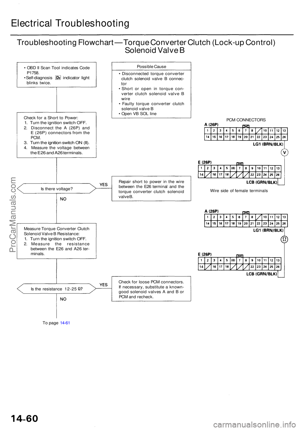
Electrical Troubleshootin g
Troubleshooting Flowchar t — Torqu e Converte r Clutc h (Lock-u p Control )
Solenoi d Valv e B
• OB D II Sca n Too l indicate s Cod e
P1758 .
• Self-diagnosi s indicator ligh tblink s twice .
Chec k fo r a Shor t t o Power :
1. Tur n th e ignitio n switc h OFF .2. Disconnec t th e A (26P ) an dE (26P ) connector s fro m th ePCM .3. Tur n th e ignitio n switc h O N (II) .4. Measur e th e voltag e betwee nthe E2 6 an d A2 6 terminals .
Is ther e voltage ?
Measur e Torqu e Converte r Clutc h
Solenoi d Valv e B Resistance :
1. Tur n th e ignitio n switc h OFF .2. Measur e th e resistanc e
betwee n th e E2 6 an d A2 6 ter -
minals .
Is th e resistanc e 12-2 5
T o pag e 14-6 1 Possibl
e Caus e
• Disconnecte d torqu e converte r
clutc h solenoi d valv e B connec -
tor• Shor t o r ope n i n torqu e con -
verte r clutc h solenoi d valv e B
wir e• Fault y torqu e converte r clutc h
solenoi d valv e B
• Ope n V B SO L lin e
Repai r shor t t o powe r i n th e wir e
betwee n th e E2 6 termina l an d th e
torqu e converte r clutc h solenoi d
valv e B .
Chec k fo r loos e PC M connectors .
I f necessary , substitut e a known -
goo d solenoi d valve s A an d B or
PC M an d recheck . PC
M CONNECTOR S
Wir e sid e o f femal e terminal s
ProCarManuals.com
Page 784 of 1954
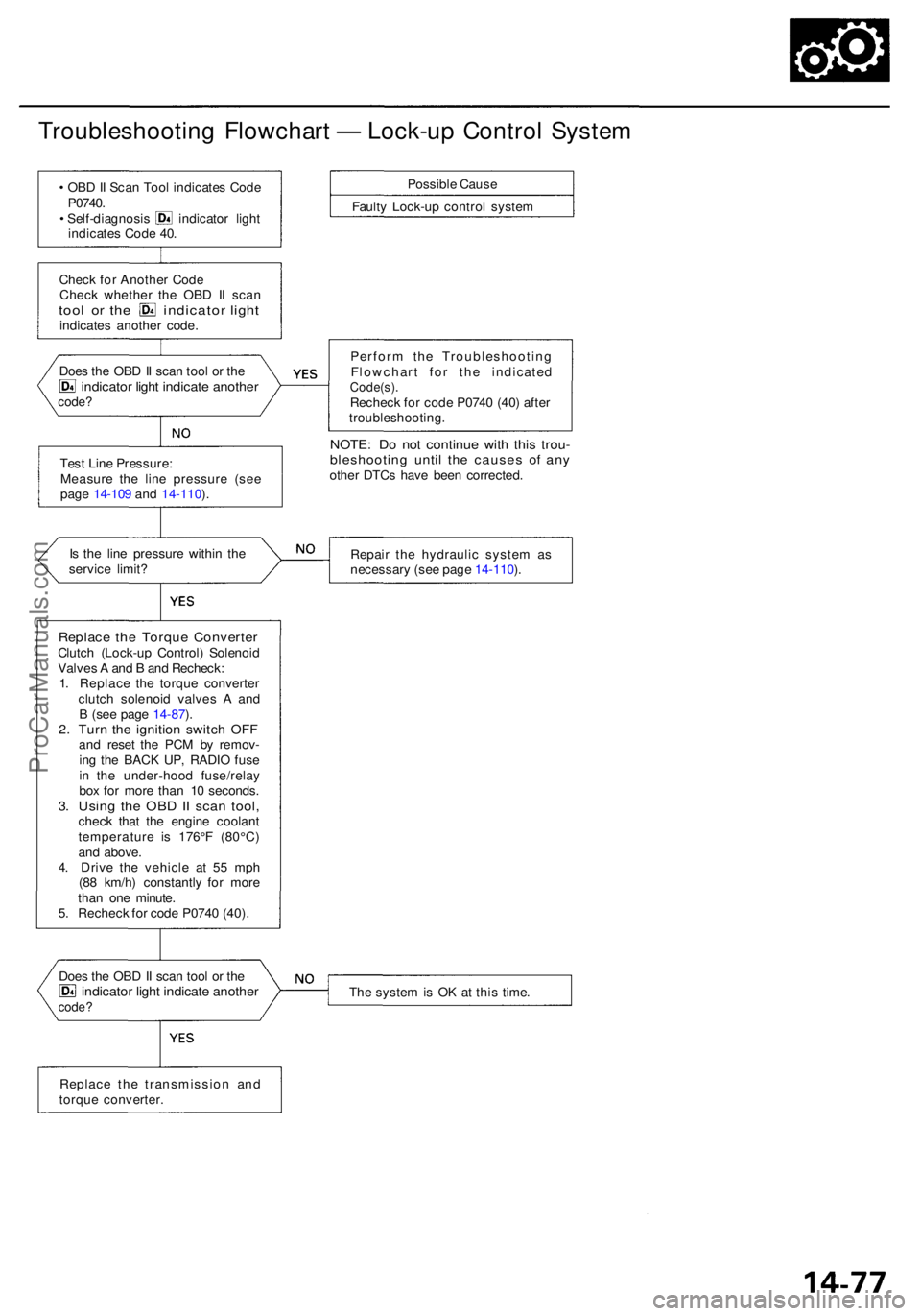
Troubleshooting Flowchar t — Lock-u p Contro l Syste m
• OB D II Sca n Too l indicate s Cod e
P0740 .
• Self-diagnosi s indicato r ligh t
indicate s Cod e 40 .
Chec k fo r Anothe r Cod e
Chec k whethe r th e OB D I I sca n
tool o r th e indicato r ligh tindicate s anothe r code .
Tes t Lin e Pressure :
Measur e th e lin e pressur e (se e
pag e 14-10 9 an d 14-110 ).
I s th e lin e pressur e withi n th e
servic e limit ?
Replac e the Torqu e Converte rClutch (Lock-u p Control ) Solenoi d
Valve s A an d B an d Recheck :
1 . Replac e th e torqu e converte r
clutc h solenoi d valve s A an d
B (se e pag e 14-87 ).
2 . Tur n th e ignitio n switc h OF Fand rese t th e PC M b y remov -
in g th e BAC K UP , RADI O fus e
i n th e under-hoo d fuse/rela y
bo x fo r mor e tha n 1 0 seconds .
3. Usin g th e OB D II sca n tool ,check tha t th e engin e coolan t
temperatur e i s 176° F (80°C )
an d above .
4 . Driv e th e vehicl e a t 5 5 mp h
(8 8 km/h ) constantl y fo r mor e
tha n on e minute .
5 . Rechec k fo r cod e P074 0 (40) .
Doe s th e OB D II sca n too l o r th e
indicato r ligh t indicat e anothe rcode?
Possibl e Caus e
Fault y Lock-u p contro l syste m
Perfor m th e Troubleshootin g
Flowchar t fo r th e indicate d
Code(s).Recheck fo r cod e P074 0 (40 ) afte r
troubleshooting .
NOTE: D o no t continu e wit h thi s trou -bleshootin g unti l th e cause s o f an yothe r DTC s hav e bee n corrected .
Repai r th e hydrauli c syste m a s
necessar y (se e pag e 14-110 ).
Th e syste m is O K a t thi s time .
Doe
s th e OB D II sca n too l o r th e
indicato r ligh t indicat e anothe rcode?
Replac e th e transmissio n an d
torqu e converter .
ProCarManuals.com
Page 793 of 1954
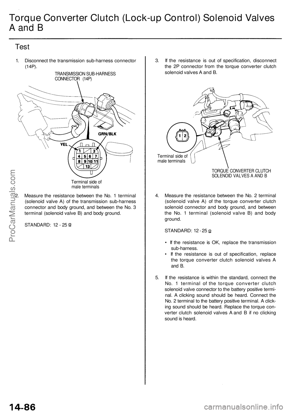
Torque Converter Clutch (Lock-up Control) Solenoid Valves
A an d B
Tes t
1. Disconnec t th e transmissio n sub-harnes s connecto r
(14P).
2. Measur e th e resistanc e betwee n th e No . 1 termina l
(solenoi d valv e A ) o f th e transmissio n sub-harnes s
connecto r an d bod y ground , an d betwee n th e No . 3
termina l (solenoi d valv e B ) an d bod y ground . 3
. I f th e resistanc e i s ou t o f specification , disconnec t
th e 2 P connecto r fro m th e torqu e converte r clutc h
solenoi d valve s A an d B .
Termina l sid e o fmal e terminal s
TORQUE CONVERTE R CLUTC HSOLENOI D VALVE S A AN D B
4. Measur e th e resistanc e betwee n th e No . 2 termina l
(solenoi d valv e A ) o f th e torqu e converte r clutc h
solenoi d connecto r an d bod y ground , an d betwee n
th e No . 1 termina l (solenoi d valv e B ) an d bod y
ground .
STANDARD : 1 2 - 2 5
• I f th e resistanc e i s OK , replac e th e transmissio n
sub-harness.
• I f th e resistance is ou t o f specification , replac e
th e torqu e converte r clutc h solenoi d valve s A
an d B .
5. I f th e resistanc e i s withi n th e standard , connec t th e
No . 1 termina l o f th e torqu e converte r clutc h
solenoi d valv e connecto r t o th e batter y positiv e termi -
nal . A clickin g soun d shoul d b e heard . Connec t th e
No . 2 termina l t o th e batter y positiv e terminal . A click -
in g soun d shoul d b e heard . Replac e th e torqu e con -
verte r clutc h solenoi d valve s A an d B if n o clickin g
soun d is heard .
TRANSMISSIO N SUB-HARNES SCONNECTOR (14P )
Termina l sid e o fmal e terminal s
STANDARD : 1 2 - 2 5
ProCarManuals.com
Page 794 of 1954
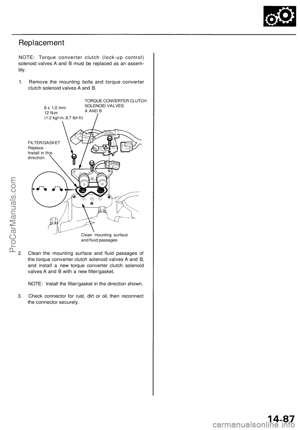
Replacement
NOTE: Torque converter clutch (lock-up control)
solenoid valves A and B must be replaced as an assem-
bly.
1. Remove the mounting bolts and torque converter
clutch solenoid valves A and B.
6 x 1.0 mm
12 N-m
(1.2 kgf-m, 8.7 Ibf-ft)
TORQUE CONVERTER CLUTCH
SOLENOID VALVES
A AND B
FILTER/GASKET
Replace.
Install in this
direction.
Clean mounting surface
and fluid passages
2. Clean the mounting surface and fluid passages of
the torque converter clutch solenoid valves A and B,
and install a new torque converter clutch solenoid
valves A and B with a new filter/gasket.
NOTE: Install the filter/gasket in the direction shown.
3. Check connector for rust, dirt or oil, then reconnect
the connector securely.ProCarManuals.com
Page 800 of 1954
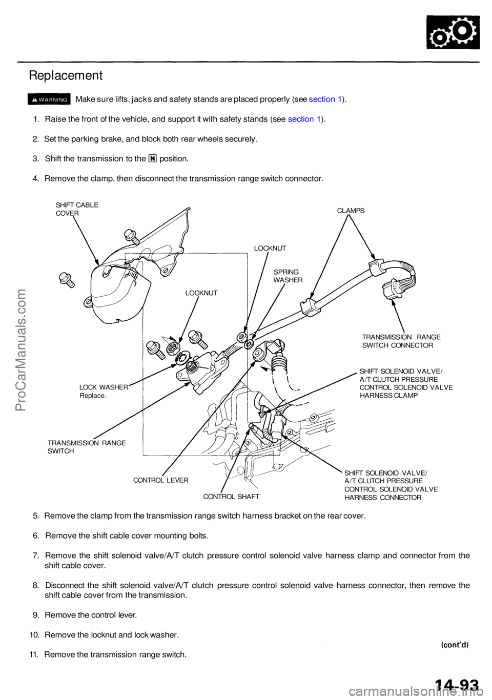
Replacement
Make sur e lifts , jack s an d safet y stand s ar e place d properl y (se e sectio n 1 ).
1 . Rais e th e fron t o f th e vehicle , an d suppor t i t wit h safet y stand s (se e sectio n 1 ).
2 . Se t th e parkin g brake , an d bloc k bot h rea r wheel s securely .
3. Shif t th e transmissio n to th e position .
4 . Remov e th e clamp , the n disconnec t th e transmissio n rang e switc h connector .
SHIFT CABL ECOVERCLAMP S
TRANSMISSIO N RANG E
SWITC H CONNECTO R
SHIF T SOLENOI D VALVE /
A/ T CLUTC H PRESSUR E
CONTRO L SOLENOI D VALV E
HARNES S CLAM P
TRANSMISSIO N RANG E
SWITC H
SHIFT SOLENOI D VALVE /
A/ T CLUTC H PRESSUR E
CONTRO L SOLENOI D VALV E
HARNES S CONNECTO R
5. Remov e th e clam p fro m th e transmissio n rang e switc h harnes s bracke t o n th e rea r cover .
6 . Remov e th e shif t cabl e cove r mountin g bolts .
7 . Remov e th e shif t solenoi d valve/A/ T clutc h pressur e contro l solenoi d valv e harnes s clam p an d connecto r fro m th e
shif t cabl e cover .
8 . Disconnec t th e shif t solenoi d valve/A/ T clutc h pressur e contro l solenoi d valv e harnes s connector , the n remov e th e
shif t cabl e cove r fro m th e transmission .
9. Remov e th e contro l lever .
10. Remov e th e locknu t an d loc k washer .
11 . Remov e th e transmissio n rang e switch .
LOCKNU T
LOCK WASHE RReplace.
CONTRO L SHAF T
CONTRO L LEVE R
SPRIN G
WASHE R
LOCKNU
T
ProCarManuals.com
Page 801 of 1954
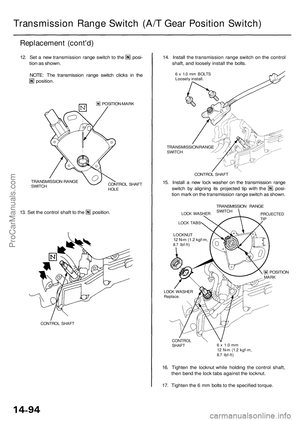
Transmission Range Switch (A/T Gear Position Switch)
Replacement (cont'd)
12. Set a new transmission range switch to the posi-
tion as shown.
NOTE: The transmission range switch clicks in the
position.
POSITION MARK
TRANSMISSION RANGE
SWITCH
CONTROL SHAFT
HOLE
13. Set the control shaft to the position.
CONTROL SHAFT
14. Install the transmission range switch on the control
shaft, and loosely install the bolts.
6 x 1.0 mm BOLTS
Loosely install.
TRANSMISSION RANGE
SWITCH
CONTROL SHAFT
15. Install a new lock washer on the transmission range
switch by aligning its projected tip with the posi-
tion mark on the transmission range switch as shown.
LOCK WASHER
LOCK TABS
LOCKNUT
12 N-m (1.2 kgf-m,
8.7 Ibf-ft)
TRANSMISSION RANGE
SWITCH
PROJECTED
TIP
POSITION
MARK
LOCK WASHER
Replace.
CONTROL
SHAFT
6 x 1.0 mm
12 N-m (1.2 kgf-m,
8.7 Ibf-ft)
16. Tighten the locknut while holding the control shaft,
then bend the lock tabs against the locknut.
17. Tighten the 6 mm bolts to the specified torque.ProCarManuals.com