1996 ACURA RL KA9 lock
[x] Cancel search: lockPage 491 of 1954

Radiator
Engine Coolan t Refillin g an d Bleedin g
'01 model :
CAUTION : Whe n pourin g engin e coolant , b e sur e t o
shu t th e rela y bo x li d an d no t t o le t coolan t spil l o n th e
electrica l part s o r th e paint . I f an y coolan t spills , rins e it
of f immediately .
NOTE:
Perfor m thi s procedur e whe n th e engin e is cool .
Befor e replacin g th e coolant , tur n th e ignitio n O N (II) ,
slowl y tur n th e climat e contro l temperatur e kno b t o
90° , an d tur n of f th e ignition . Thi s wil l allo w th e
coolan t i n th e heate r t o drai n ou t wit h th e res t o f th e
system .
Whe n th e radiato r i s cool , remov e th e radiato r cap .
Loose n th e drai n plug , an d drai n th e coolant .
DRAINPLUG
DRAI N CA P
2. Remov e th e drai n ca p fro m th e coolan t drai n pip e
t o drai n th e block .
3 . Pu t th e drai n ca p bac k i n place , the n reinstal l th e
cli p o n th e drai n ca p securely .
4 . Tighte n th e radiato r drai n plu g securely .
5 . Remove , drai n an d reinstal l th e coolan t reservoir .
Fil l th e tan k t o th e MA X mar k wit h Hond a Al l
Seaso n Antifreeze/Coolan t Typ e 2 .
6 . Remov e th e engine cover (se e pag e 5-3 ). 7
. Loose n th e ai r blee d bol t i n th e thermosta t housing ,
the n pou r Hond a Al l Seaso n Antifreeze/Coolan t
Typ e 2 int o th e radiato r t o th e botto m o f th e fille r
neck . D o no t le t coolan t spil l o n an y electrica l part s
o r th e paint . I f an y coolan t spills , rins e i t of f immedi -
ately .
NOTE :
Alway s us e Hond a Al l Seaso n Antifreeze/Coolan t
Typ e 2 . Usin g a non-Hond a coolan t ca n resul t i n
corrosion , causin g th e coolin g syste m to mal -
functio n o r fail .
Hond a Al l Seaso n Antifreeze/Coolan t Typ e 2 is a
mixtur e o f 50 % antifreez e an d 50 % water . Pre -
mixin g i s no t required .
8 . Tighte n th e blee d bol t a s soo n a s coolan t start s t o
ru n ou t i n a stead y stream .
9 . Wit h th e radiato r cap off, star t th e engin e an d le t i t
ru n unti l warme d u p (radiato r fa n come s o n a t leas t
twice) . Then , i f necessary , ad d mor e genuin e Hond a
Al l Seaso n Antifreeze/Coolan t Typ e 2 to brin g th e
leve l bac k u p t o th e botto m o f th e fille r neck .
10 . Pu t th e radiato r ca p o n tightly , the n ru n th e engin e
agai n an d chec k fo r leaks .
Engin
e Coolan t Refil l Capacit y [Includin g reservoi r
(0.65 (0.6 9 U S qt , 0.5 7 Im p qt))] :
6.1 (6. 4 US qt , 5. 4 Im p qt )
BLEE D BOL T9.8 N- m (1. 0 kgf-m , 7. 2 Ibf-ft )
ProCarManuals.com
Page 496 of 1954
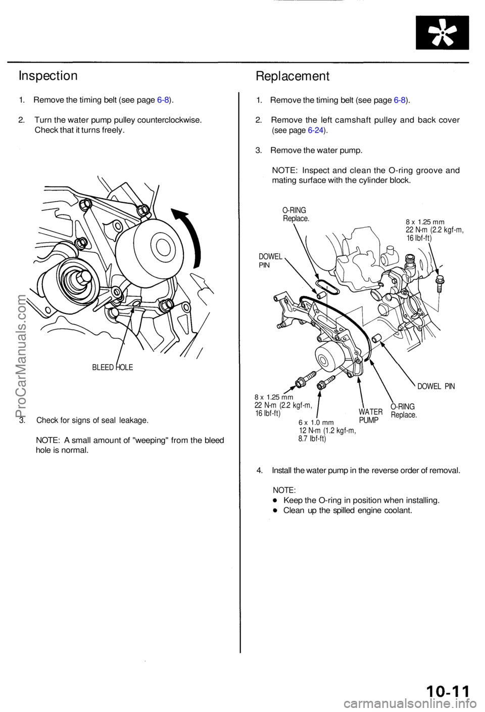
Inspection
1. Remov e th e timin g bel t (se e pag e 6-8 ).
2 . Tur n th e wate r pum p pulle y counterclockwise .
Chec k tha t i t turn s freely .
BLEED HOL E
3. Chec k fo r sign s o f sea l leakage .
NOTE: A smal l amoun t o f "weeping " fro m th e blee d
hol e is normal .
Replacemen t
1. Remov e th e timin g bel t (se e pag e 6-8 ).
2 . Remov e th e lef t camshaf t pulle y an d bac k cove r
(see pag e 6-24 ).
3 . Remov e th e wate r pump .
NOTE : Inspec t an d clea n th e O-rin g groov e an d
matin g surfac e wit h th e cylinde r block .
O-RIN GReplace .8 x 1.2 5 mm22 N- m (2. 2 kgf-m ,
1 6 Ibf-ft )
DOWE LPIN
DOWE L PI N
8 x 1.2 5 mm22 N- m (2. 2 kgf-m ,
1 6 Ibf-ft )
6 x 1. 0 m m12 N- m (1. 2 kgf-m ,
8. 7 Ibf-ft )
4. Instal l th e wate r pum p in th e revers e orde r o f removal .
NOTE:
Keep th e O-rin g in positio n whe n installing .
Clea n u p th e spille d engin e coolant .
WATERPUMP
O-RIN GReplace .
ProCarManuals.com
Page 543 of 1954
Troubleshooting
Troubleshooting Procedure s (cont'd )
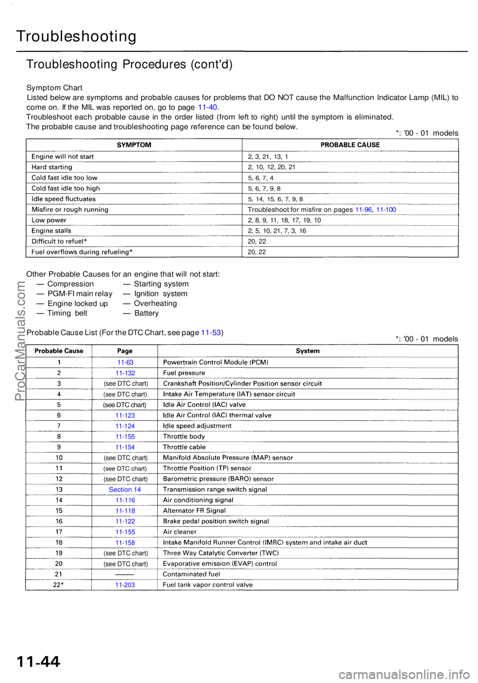
Sympto m Char t
Liste d belo w ar e symptom s an d probabl e cause s fo r problem s tha t D O NO T caus e th e Malfunctio n Indicato r Lam p (MIL ) t o
com e on . I f th e MI L wa s reporte d on , g o t o pag e 11-40 .
Troubleshoo t eac h probabl e caus e i n th e orde r liste d (fro m lef t t o right ) unti l th e sympto m is eliminated .
Th e probabl e caus e an d troubleshootin g pag e referenc e ca n b e foun d below .
*: '0 0 - 0 1 model s
2, 3 , 21 , 13 , 1
2 , 10 , 12 , 20 , 2 1
5, 6 , 7 , 4
5 , 6 , 7 , 9 , 8
5 , 14 , 15 , 6 , 7 , 9 , 8
Troubleshoo t fo r misfir e o n page s 11-96 , 11-10 0
2, 8 , 9 , 11 , 18 , 17 , 19 , 1 0
2, 5 , 10 , 21 , 7 , 3 , 1 6
20 , 2 2
20 , 2 2
Othe r Probabl e Cause s fo r a n engin e tha t wil l no t start :
Compressio n
PGM-FI mai n rela y
Engin e locke d u p
Timin g bel t Startin
g syste m
Ignitio n syste m
Overheatin g
Battery
Probabl e Caus e Lis t (Fo r th e DT C Chart , se e pag e 11-53 )
*: '0 0 - 0 1 model s
11-63
11-13 2
(see DTC chart)
(see DTC chart)
(see DTC chart)
11-12 3
11-124
11-155
11-154
(see DTC chart)
(see DTC chart)
(see DTC chart)
Sectio n 1 4
11-11 6
11-118
11-122
11-15 5
11-158
(see DTC chart)
(see DTC chart)
11-20 3
ProCarManuals.com
Page 599 of 1954
PGM-FI Syste m
Rando m Misfir e
The sca n too l indicate s Diagnosti c Troubl e Cod e (DTC ) P0300*3,
P1300*4 an d som e o f P120 1 - P120 6 o r som e o f P130 1 - P1306 :
Rando m misfire .
Descriptio n
Misfir e detectio n i s accomplishe d b y monitorin g th e voltag e o f th e spar k plu g wit h th e spar k plu g voltag e senso r whic h i s
buil t i n to th e ignitio n coil .
If misfirin g stron g enoug h t o damag e th e catalys t i s detected , th e MI L wil l blin k durin g th e tim e o f it s occurrence , an d DT C
P1300*3 o r P0300*4, som e o f DTC s P120 1 throug h P120 6 o r som e o f DTC s P130 1 throug h P130 6 wil l b e stored . Then , afte r
misfir e ha s ceased , th e MI L wil l com e o n an d sta y o n wheneve r th e ignitio n switc h i s O N (II) .
I f misfirin g tha t increase s emission s i s detecte d durin g tw o consecutiv e drivin g cycles , th e MI L wil l com e on , an d DT C
P1300*
3 o r P0300*4, som e o f DTC s P120 1 throug h P120 6 o r som e o f DTC s P130 1 throug h P130 6 wil l b e stored .
NOTE : I f som e o f th e DTC s liste d belo w ar e store d a t th e sam e tim e a s a misfir e DTC , troubleshoo t thos e DTC s first , the n
troubleshoo t th e misfir e DTC .
P0106*1, P1128*2, P1129*2: MA P senso r
P0171 , P0172 , P0174 , P0175 : Fue l meterin g
P0401 , P1491 , PU98 : EG R syste m
P0335 , P0336 , P1336 , P1337 , P1381 , P1382 , P1386 , P1387 : CKP/CY P senso r
P0505 : Idl e Contro l Syste m
PI508 : IA C valv e
*1 : '9 6 mode l onl y
*2 : '9 7 - 0 1 model s
*3: '9 6 - 9 7 model s
*4: '9 8 - 0 1 model s
Possibl e Caus e
Fuel pum p insufficien t fue l pressure , amoun t o f flo w
Fue l lin e clogging , blockage , leakag e
Fue l filte r cloggin g
Fue l pressur e regulato r stuc k ope n
EG R syste m malfunctio n
Ignitio n coi l wir e open , leakag e
Ignition contro l modul e malfunction
MA P senso r range/performance , poo r response*1
IA C valv e malfunctio n
Fas t idl e therm o valv e malfunctio n
Carbo n deposit s o n valve s
Compressio n lo w
Gasolin e doe s no t mee t Owner' s Manua l spec. , lac k o f fue l
Troubleshootin g
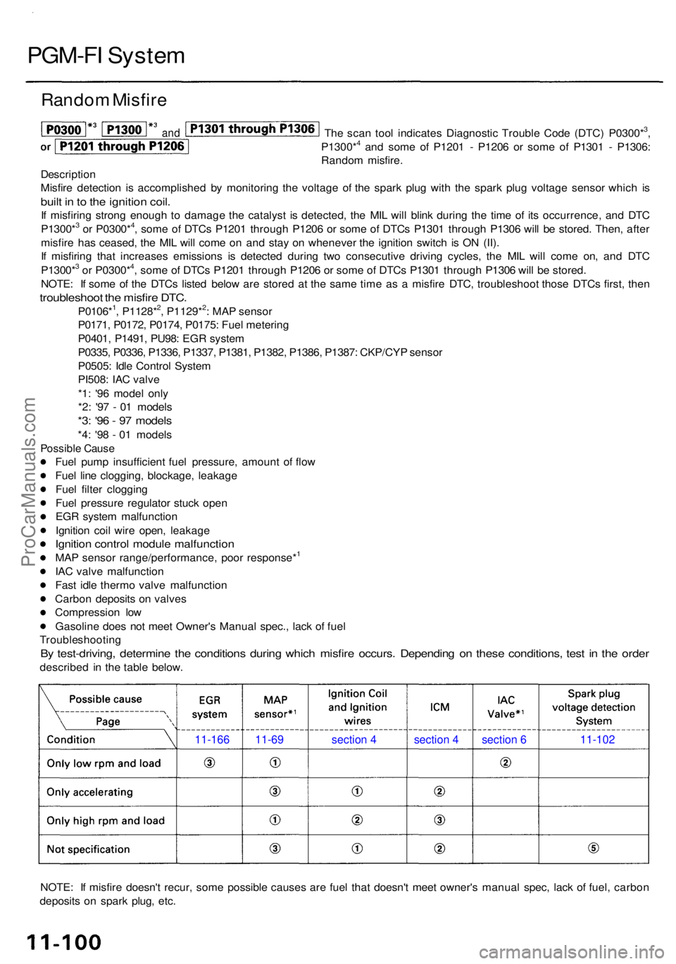
By test-driving , determin e th e condition s durin g whic h misfir e occurs . Dependin g o n thes e conditions , tes t i n th e orde r
describe d i n th e tabl e below .
NOTE : I f misfir e doesn' t recur , som e possibl e cause s ar e fue l tha t doesn' t mee t owner' s manua l spec , lac k o f fuel , carbo n
deposit s o n spar k plug , etc .
11-166 11-69 section 4 section 4 section 6 11-102
and
ProCarManuals.com
Page 619 of 1954
Idle Contro l Syste m
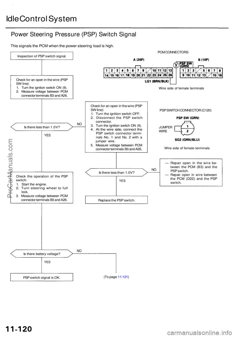
Power Steerin g Pressur e (PSP ) Switc h Signa l
This signal s th e PC M whe n th e powe r steerin g loa d is high .
Inspectio n o f PS P switc h signal .
Chec k fo r a n ope n in th e wir e (PS P
S W line) :
1 . Tur n th e ignitio n switc h O N (II) .
2 . Measur e voltag e betwee n PC M
connecto r terminal s B 3 an d A26 .
I s ther e les s tha n 1.0V ?
NO
YE S
Chec k th e operatio n o f th e PS P
switch :
1 . Star t th e engine .
2. Tur n steerin g whee l t o ful llock .
3 . Measur e voltag e betwee n PC M
connecto r terminal s B 3 an d A26 .
I s ther e batter y voltage ?
NO
PC M CONNECTOR S
Chec k fo r a n ope n in th e wir e (PS P
S W Iine) :
1 . Tur n th e ignitio n switc h OFF .
2 . Disconnec t th e PS P switc h
connector .
3 . Tur n th e ignitio n switc h O N (II) .
4. A t th e wir e side , connec t th ePS P switc h connecto r termi -
nal s No . 1 an d No . 2 wit h a
jumpe r wire .
5 . Measur e voltag e betwee n PC M
connecto r terminal s B 3 an d A26 . Wir
e sid e o f femal e terminal s
PS P SWITC H CONNECTO R (C120 )
JUMPE RWIRE
Wire sid e o f femal e terminal s
I s ther e les s tha n 1.0V ?
NO
— Repai r ope n i n th e wire be-
twee n th e PC M (B3 ) an d th e
PS P switch .
— Repai r ope n i n wir e betwee n
the PC M (D22 ) and th e PS Pswitch .
(T o pag e 11-121 )
PS P switc h signa l i s OK .
YES
Replac e th e PS P switch .
YES
ProCarManuals.com
Page 629 of 1954
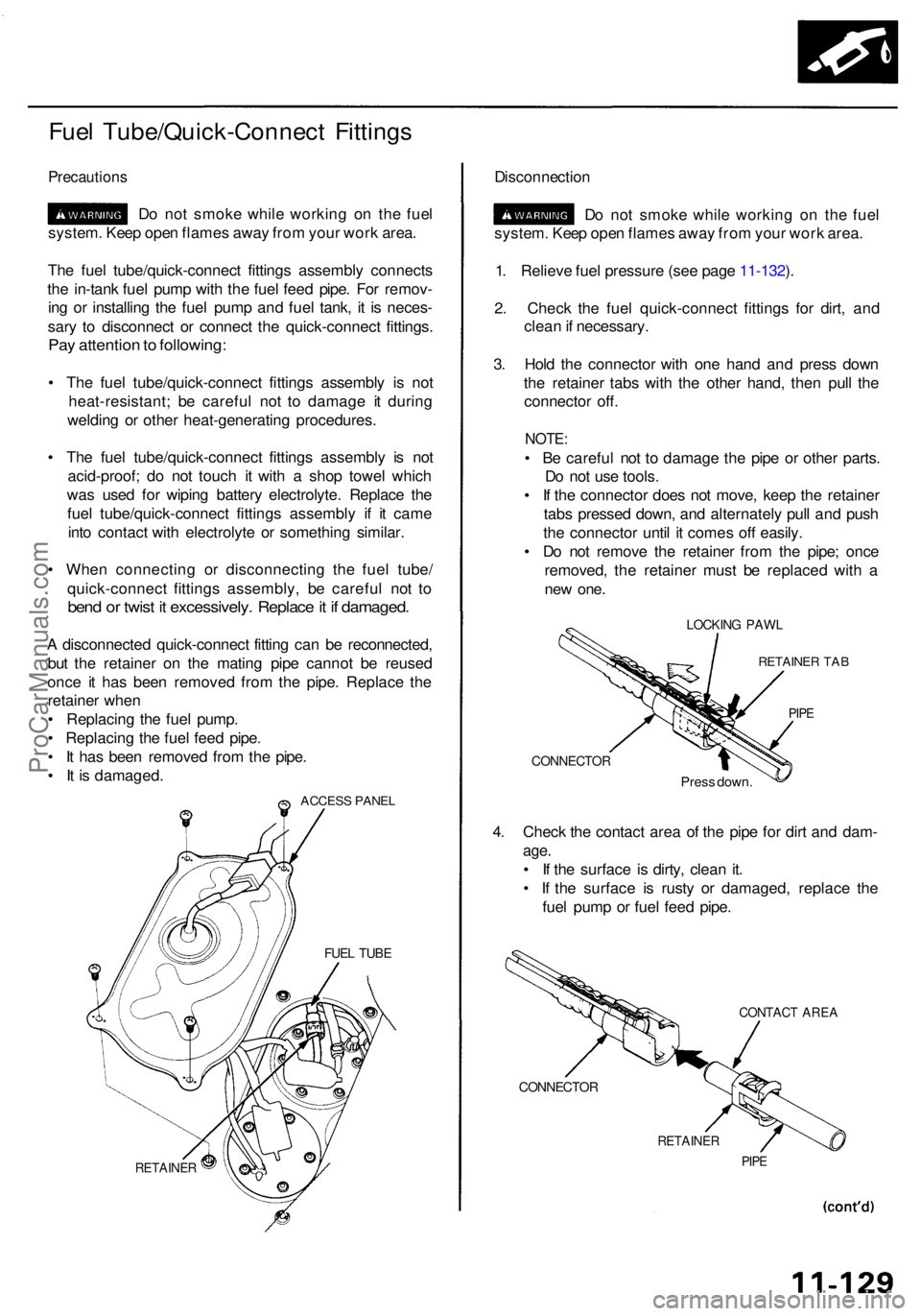
Fuel Tube/Quick-Connec t Fitting s
Precaution s
Do no t smok e whil e workin g o n th e fue l
system . Kee p ope n flame s awa y fro m you r wor k area .
Th e fue l tube/quick-connec t fitting s assembl y connect s
th e in-tan k fue l pum p wit h th e fue l fee d pipe . Fo r remov -
in g o r installin g th e fue l pum p an d fue l tank , i t i s neces -
sar y t o disconnec t o r connec t th e quick-connec t fittings .
Pay attentio n to following :
• Th e fue l tube/quick-connec t fitting s assembl y i s no t
heat-resistant ; b e carefu l no t t o damag e i t durin g
weldin g o r othe r heat-generatin g procedures .
• Th e fue l tube/quick-connec t fitting s assembl y i s no t
acid-proof ; d o no t touc h i t wit h a sho p towe l whic h
wa s use d fo r wipin g batter y electrolyte . Replac e th e
fue l tube/quick-connec t fitting s assembl y i f i t cam e
int o contac t wit h electrolyt e o r somethin g similar .
• Whe n connectin g o r disconnectin g th e fue l tube /
quick-connec t fitting s assembly , b e carefu l no t t o
ben d o r twis t i t excessively . Replac e it i f damaged .
A disconnecte d quick-connec t fittin g ca n b e reconnected ,
bu t th e retaine r o n th e matin g pip e canno t b e reuse d
onc e i t ha s bee n remove d fro m th e pipe . Replac e th e
retaine r whe n
• Replacin g th e fue l pump .
• Replacin g th e fue l fee d pipe .
• I t ha s bee n remove d fro m th e pipe .
• I t i s damaged .
ACCESS PANE L
RETAINE R
Disconnectio n
D o no t smok e whil e workin g o n th e fue l
system . Kee p ope n flame s awa y fro m you r wor k area .
1 . Reliev e fue l pressur e (se e pag e 11-132 ).
2 . Chec k th e fue l quick-connec t fitting s fo r dirt , an d
clea n if necessary .
3 . Hol d th e connecto r wit h on e han d an d pres s dow n
th e retaine r tab s wit h th e othe r hand , the n pul l th e
connecto r off .
NOTE :
• B e carefu l no t t o damag e th e pip e o r othe r parts .
D o no t us e tools .
• I f th e connecto r doe s no t move , kee p th e retaine r
tab s presse d down , an d alternatel y pul l an d pus h
th e connecto r unti l i t come s of f easily .
• D o no t remov e th e retaine r fro m th e pipe ; onc e
removed , th e retaine r mus t b e replace d wit h a
ne w one .
LOCKIN G PAW L
RETAINE R TA B
PIPE
CONNECTO R
Press down .
4. Chec k th e contac t are a o f th e pip e fo r dir t an d dam -
age.
• I f th e surfac e i s dirty , clea n it .
• I f th e surfac e i s rust y o r damaged , replac e th e
fue l pum p o r fue l fee d pipe .
CONTAC T ARE A
CONNECTO R
RETAINER
PIPE
FUE L TUB E
ProCarManuals.com
Page 631 of 1954
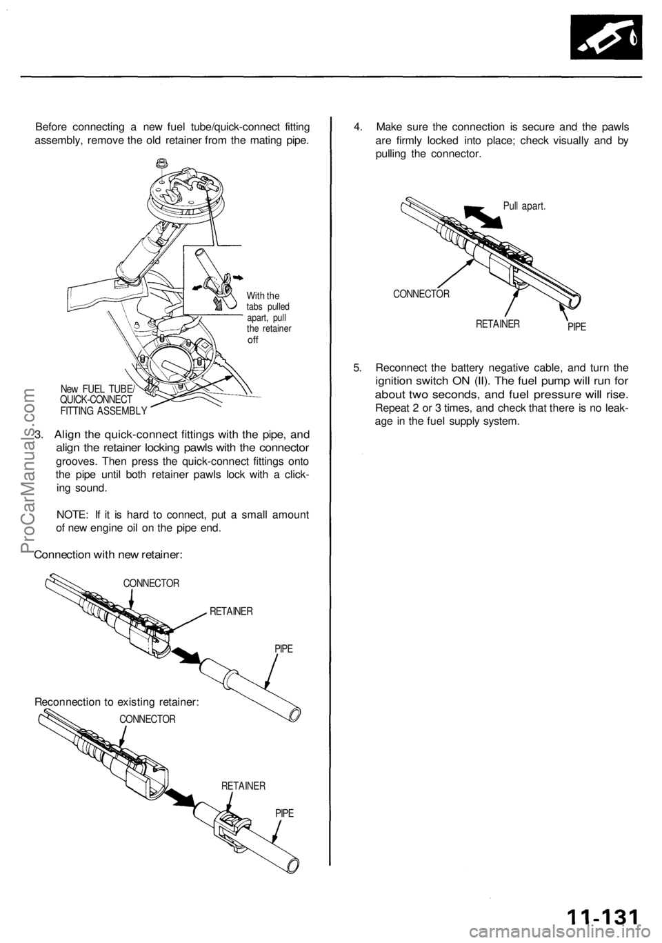
Before connectin g a ne w fue l tube/quick-connec t fittin g
assembly , remov e th e ol d retaine r fro m th e matin g pipe .
With th etab s pulle d
apart , pul l
th e retaine r
off
Ne w FUE L TUBE /
QUICK-CONNEC T
FITTIN G ASSEMBL Y
3. Alig n th e quick-connec t fitting s wit h th e pipe , an d
align th e retaine r lockin g pawl s wit h th e connecto r
grooves. The n pres s th e quick-connec t fitting s ont o
th e pip e unti l bot h retaine r pawl s loc k wit h a click -
in g sound .
NOTE : I f i t i s har d t o connect , pu t a smal l amoun t
o f ne w engin e oi l o n th e pip e end .
Connectio n wit h ne w retainer :
CONNECTO R
RETAINER
RETAINE R
PIPE
4. Mak e sur e th e connectio n i s secur e an d th e pawl s
ar e firml y locke d int o place ; chec k visuall y an d b y
pullin g th e connector .
Pull apart .
CONNECTO R
RETAINERPIPE
5. Reconnec t th e batter y negativ e cable , an d tur n th e
ignitio n switc h O N (II) . Th e fue l pum p wil l ru n fo r
abou t tw o seconds , an d fue l pressur e wil l rise .
Repea t 2 o r 3 times , an d chec k tha t ther e is n o leak -
ag e in th e fue l suppl y system .
CONNECTO R
Reconnectio n to existin g retainer :
PIPE
ProCarManuals.com
Page 636 of 1954
Fuel Suppl y Syste m
Fuel Pressur e Regulato r (cont'd )
Remova l
Do no t smok e whil e workin g o n fue l sys -
tem . Kee p ope n flam e awa y fro m you r wor k area .
1 . Remov e th e stru t bar .
2 . Remov e th e engin e cover .
3 . Reliev e fue l pressur e (pag e 11-132 ).
4 . Disconnec t th e vacuu m hos e an d fue l retur n hose .
5 . Loose n th e lockin g nut , an d remov e th e fue l pres -
sur e regulator .
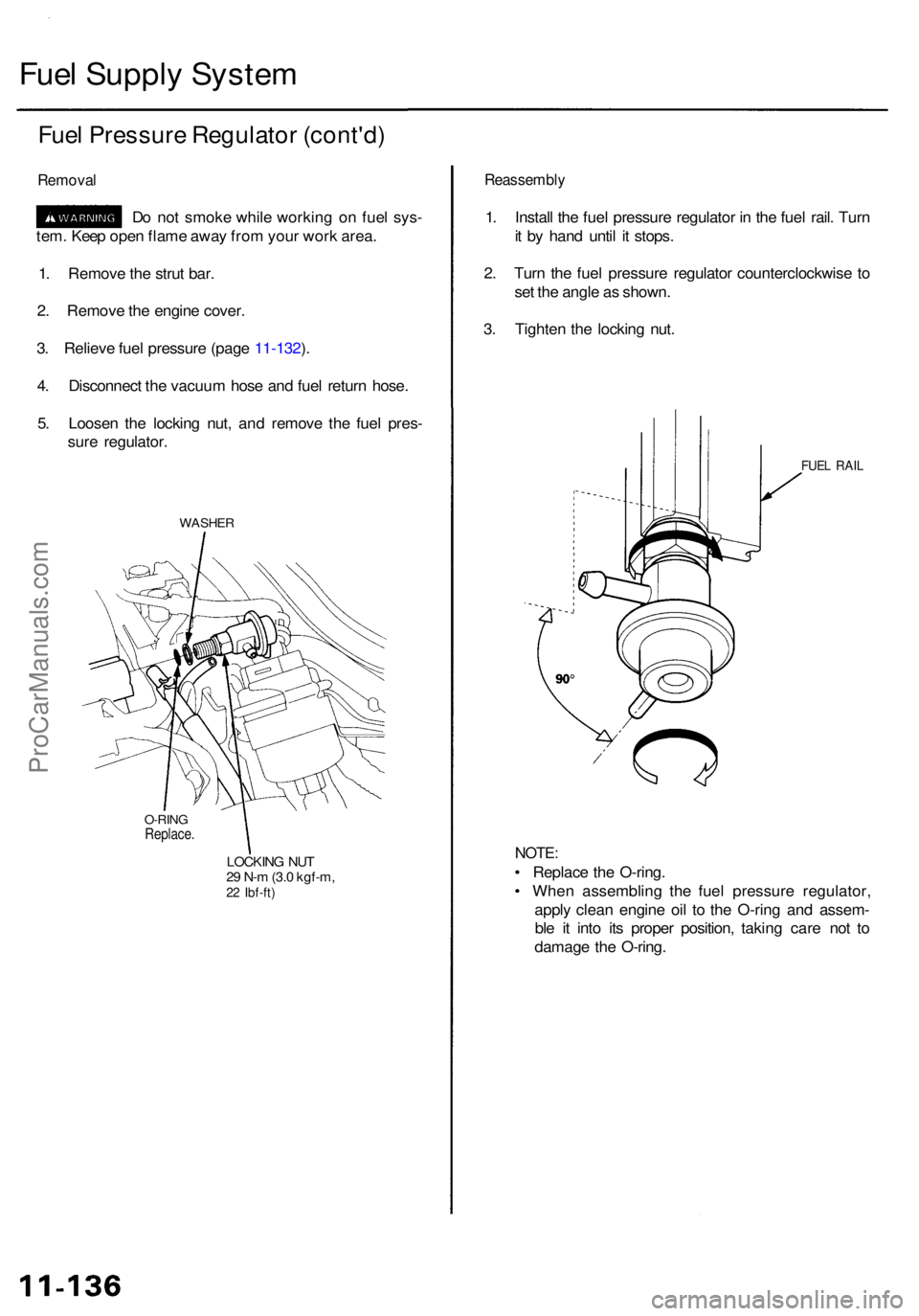
WASHER
O-RINGReplace .
LOCKING NU T
2 9 N- m (3. 0 kgf-m ,
22 Ibf-ft )
Reassembl y
1. Instal l th e fue l pressur e regulato r i n th e fue l rail . Tur n
i t b y han d unti l i t stops .
2 . Tur n th e fue l pressur e regulato r counterclockwis e t o
se t th e angl e a s shown .
3 . Tighte n th e lockin g nut .
FUE L RAI L
NOTE :
• Replac e th e O-ring .
• Whe n assemblin g th e fue l pressur e regulator ,
appl y clea n engin e oi l t o th e O-rin g an d assem -
bl e i t int o it s prope r position , takin g car e no t t o
damag e th e O-ring .
ProCarManuals.com