Page 1813 of 2543
7. REMOVE UPPER SUSPENSION ARM
(a) Remove the bolt and nut.
Torque: 164 NVm (1,670 kgfVcm, 121 ftVlbf)
INSTALLATION HINT: After stabilizing the suspension
torque the nut.
(b) Remove the upper suspension arm.
UPPER BALL JOINT INSPECTION
INSPECT BALL JOINT FOR ROTATION CONDITION
(a) As shown, flip the ball joint stud back and forth 5 times before
installing the nut.
(b) Using a torque wrench, turn the nut continuously one turn
every 2±4 seconds and take the torque reading on the 5th
turn.
Torque (turning):
1.0±3.4 NVm (10±35 kgfVcm, 9±30 in.Vlbf)
If not within specification, replace the upper suspension arm.
Corrected 6/21/01 ± MH SA±28
± SUSPENSION AND AXLEFRONT SUSPENSION
Page 1815 of 2543

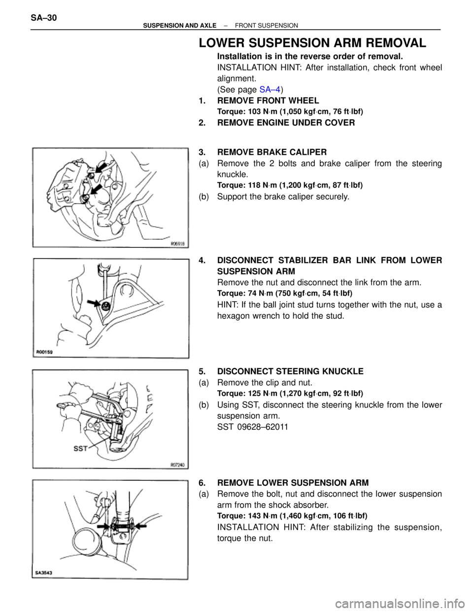
LOWER SUSPENSION ARM REMOVAL
Installation is in the reverse order of removal.
INSTALLATION HINT: After installation, check front wheel
alignment.
(See page SA±4)
1. REMOVE FRONT WHEEL
Torque: 103 NVm (1,050 kgfVcm, 76 ftVlbf)
2. REMOVE ENGINE UNDER COVER
3. REMOVE BRAKE CALIPER
(a) Remove the 2 bolts and brake caliper from the steering
knuckle.
Torque: 118 NVm (1,200 kgfVcm, 87 ftVlbf)
(b) Support the brake caliper securely.
4. DISCONNECT STABILIZER BAR LINK FROM LOWER
SUSPENSION ARM
Remove the nut and disconnect the link from the arm.
Torque: 74 NVm (750 kgfVcm, 54 ftVlbf)
HINT: If the ball joint stud turns together with the nut, use a
hexagon wrench to hold the stud.
5. DISCONNECT STEERING KNUCKLE
(a) Remove the clip and nut.
Torque: 125 NVm (1,270 kgfVcm, 92 ftVlbf)
(b) Using SST, disconnect the steering knuckle from the lower
suspension arm.
SST 09628±62011
6. REMOVE LOWER SUSPENSION ARM
(a) Remove the bolt, nut and disconnect the lower suspension
arm from the shock absorber.
Torque: 143 NVm (1,460 kgfVcm, 106 ftVlbf)
INSTALLATION HINT: After stabilizing the suspension,
torque the nut. SA±30
± SUSPENSION AND AXLEFRONT SUSPENSION
Page 1816 of 2543

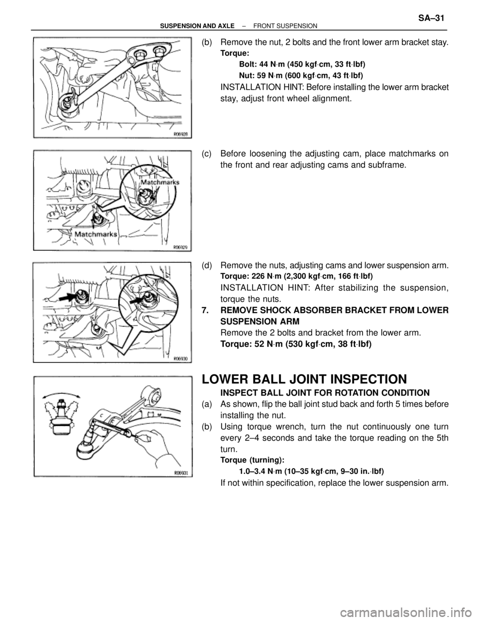
(b) Remove the nut, 2 bolts and the front lower arm bracket stay.
Torque:
Bolt: 44 NVm (450 kgfVcm, 33 ftVlbf)
Nut: 59 NVm (600 kgfVcm, 43 ftVlbf)
INSTALLATION HINT: Before installing the lower arm bracket
stay, adjust front wheel alignment.
(c) Before loosening the adjusting cam, place matchmarks on
the front and rear adjusting cams and subframe.
(d) Remove the nuts, adjusting cams and lower suspension arm.
Torque: 226 NVm (2,300 kgfVcm, 166 ftVlbf)
INSTALLATION HINT: After stabilizing the suspension,
torque the nuts.
7. REMOVE SHOCK ABSORBER BRACKET FROM LOWER
SUSPENSION ARM
Remove the 2 bolts and bracket from the lower arm.
Torque: 52 NVm (530 kgfVcm, 38 ftVlbf)
LOWER BALL JOINT INSPECTION
INSPECT BALL JOINT FOR ROTATION CONDITION
(a) As shown, flip the ball joint stud back and forth 5 times before
installing the nut.
(b) Using torque wrench, turn the nut continuously one turn
every 2±4 seconds and take the torque reading on the 5th
turn.
Torque (turning):
1.0±3.4 NVm (10±35 kgfVcm, 9±30 in.Vlbf)
If not within specification, replace the lower suspension arm.
± SUSPENSION AND AXLEFRONT SUSPENSIONSA±31
Page 1818 of 2543
STABILIZER BAR AND LINK REMOVAL
Installation is in the reverse order of removal.
1. REMOVE FRONT WHEELS
Torque: 103 NVm (1,050 kgfVcm, 76 ftVlbf)
2. REMOVE ENGINE UNDER COVER
3. REMOVE BOTH STABILIZER BAR LINKS
Remove the nuts and stabilizer bar links from the stabilizer
bar and the lower suspension arm.
Torque: 74 NVm (750 kgfVcm, 54 ftVlbf)
HINT: If the ball joint stud turns together with the nut, use a
hexagon wrench to hold the stud.
4. REMOVE STABILIZER BAR
(a) Remove the left and right apron seal set bolts.
(b) Remove the 4 bracket bolts and the stabilizer bar with the
cushions and brackets.
Torque: 18 NVm (180 kgfVcm, 13 ftVlbf)
5. REMOVE CUSHIONS AND BRACKETS
INSTALLATION HINT: Install the cushion to the outside of the
line.
± SUSPENSION AND AXLEFRONT SUSPENSIONSA±33
Page 1819 of 2543
STABILIZER BAR LINK INSPECTION
INSPECT BALL JOINT FOR ROTATION CONDITION
(a) As shown, flip the ball joint stud back and forth 5 times before
installing the nut.
(b) Using a torque wrench, turn the stud continuously one turn
every 2±4 seconds and take the torque reading on the 5th
turn.
Torque (turning):
0.05±1.0 NVm (0.5±10 kgfVcm, 0.4±8.7 in.Vlbf)
If not within specification, replace the stabilizer bar link. SA±34
± SUSPENSION AND AXLEFRONT SUSPENSION
Page 1821 of 2543
09610±20012 Pitman Arm Puller
09628±10011 Ball Joint PullerHub bolt removal
09628±62011 Ball Joint Puller
09950±40010 Puller B SetAxle bearing inner race (outside)
removal
RECOMMENDED TOOLS
09905±00013 Snap Ring PliersRear axle hub bearing
EQUIPMENT
������������������������� �
������������������������ �������������������������
Dial indicator����������� �
���������� �����������
������������������������� �
������������������������ �������������������������Torque wrench����������� �
���������� �����������
SA±36± SUSPENSION AND AXLEREAR AXLE HUB
Page 1823 of 2543
REAR AXLE CARRIER REMOVAL
Installation is in the reverse order of removal.
INSTALLATION HINT: After installation, check ABS speed
sensor signal and rear wheel alignment.
(See page BR±64 and SA±9)
1. REMOVE REAR WHEEL
Torque: 103 NVm (1,050 kgfVcm, 76 ftVlbf)
2. REMOVE REAR BRAKE CALIPER AND DISC
(a) Remove the 2 bolts and brake caliper from the rear axle hub.
Torque: 104 NVm (1,065 kgfVcm, 77 ftVlbf)
(b) Support the brake caliper securely.
(c) Place matchmarks on the disc and axle hub.
(d) Remove the disc.
3. CHECK BACKLASH IN BEARING SHAFT DIRECTION
Place the dial indicator near the center of the axle hub and
check the backlash in the bearing shaft direction.
Maximum:
0.05 mm (0.0020 in.)
If greater than the specified maximum, replace the bearing. SA±38
± SUSPENSION AND AXLEREAR AXLE HUB
Page 1824 of 2543

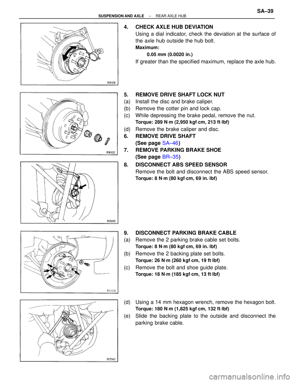
4. CHECK AXLE HUB DEVIATION
Using a dial indicator, check the deviation at the surface of
the axle hub outside the hub bolt.
Maximum:
0.05 mm (0.0020 in.)
If greater than the specified maximum, replace the axle hub.
5. REMOVE DRIVE SHAFT LOCK NUT
(a) Install the disc and brake caliper.
(b) Remove the cotter pin and lock cap.
(c) While depressing the brake pedal, remove the nut.
Torque: 289 NVm (2,950 kgfVcm, 213 ftVlbf)
(d) Remove the brake caliper and disc.
6. REMOVE DRIVE SHAFT
(See page SA±46)
7. REMOVE PARKING BRAKE SHOE
(See page BR±35)
8. DISCONNECT ABS SPEED SENSOR
Remove the bolt and disconnect the ABS speed sensor.
Torque: 8 NVm (80 kgfVcm, 69 in.Vlbf)
9. DISCONNECT PARKING BRAKE CABLE
(a) Remove the 2 parking brake cable set bolts.
Torque: 8 NVm (80 kgfVcm, 69 in.Vlbf)
(b) Remove the 2 backing plate set bolts.
Torque: 26 NVm (260 kgfVcm, 19 ftVlbf)
(c) Remove the bolt and shoe guide plate.
Torque: 18 NVm (185 kgfVcm, 13 ftVlbf)
(d) Using a 14 mm hexagon wrench, remove the hexagon bolt.
Torque: 180 NVm (1,825 kgfVcm, 132 ftVlbf)
(e) Slide the backing plate to the outside and disconnect the
parking brake cable.
± SUSPENSION AND AXLEREAR AXLE HUBSA±39