Page 1825 of 2543
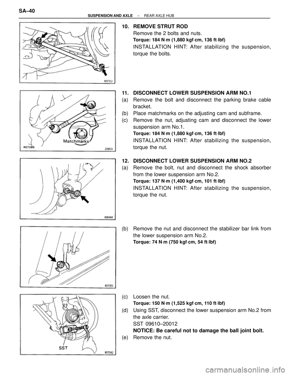
10. REMOVE STRUT ROD
Remove the 2 bolts and nuts.
Torque: 184 NVm (1,880 kgfVcm, 136 ftVlbf)
INSTALLATION HINT: After stabilizing the suspension,
torque the bolts.
11. DISCONNECT LOWER SUSPENSION ARM NO.1
(a) Remove the bolt and disconnect the parking brake cable
bracket.
(b) Place matchmarks on the adjusting cam and subframe.
(c) Remove the nut, adjusting cam and disconnect the lower
suspension arm No.1.
Torque: 184 NVm (1,880 kgfVcm, 136 ftVlbf)
INSTALLATION HINT: After stabilizing the suspension,
torque the nut.
12. DISCONNECT LOWER SUSPENSION ARM NO.2
(a) Remove the bolt, nut and disconnect the shock absorber
from the lower suspension arm No.2.
Torque: 137 NVm (1,400 kgfVcm, 101 ftVlbf)
INSTALLATION HINT: After stabilizing the suspension,
torque the nut.
(b) Remove the nut and disconnect the stabilizer bar link from
the lower suspension arm No.2.
Torque: 74 NVm (750 kgfVcm, 54 ftVlbf)
(c) Loosen the nut.
Torque: 150 NVm (1,525 kgfVcm, 110 ftVlbf)
(d) Using SST, disconnect the lower suspension arm No.2 from
the axle carrier.
SST 09610±20012
NOTICE: Be careful not to damage the ball joint bolt.
(e) Remove the nut. SA±40
± SUSPENSION AND AXLEREAR AXLE HUB
Page 1826 of 2543
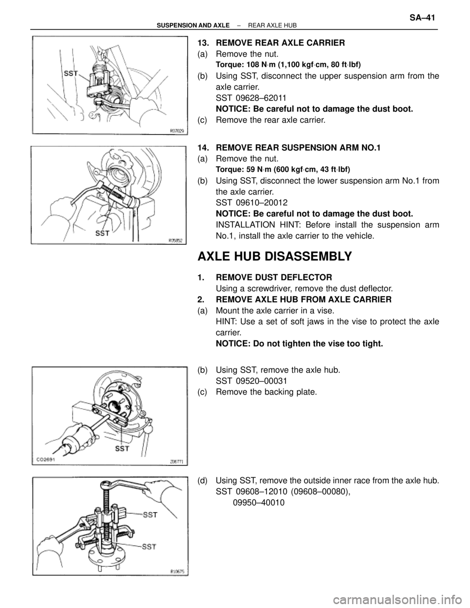
13. REMOVE REAR AXLE CARRIER
(a) Remove the nut.
Torque: 108 NVm (1,100 kgfVcm, 80 ftVlbf)
(b) Using SST, disconnect the upper suspension arm from the
axle carrier.
SST 09628±62011
NOTICE: Be careful not to damage the dust boot.
(c) Remove the rear axle carrier.
14. REMOVE REAR SUSPENSION ARM NO.1
(a) Remove the nut.
Torque: 59 NVm (600 kgfVcm, 43 ftVlbf)
(b) Using SST, disconnect the lower suspension arm No.1 from
the axle carrier.
SST 09610±20012
NOTICE: Be careful not to damage the dust boot.
INSTALLATION HINT: Before install the suspension arm
No.1, install the axle carrier to the vehicle.
AXLE HUB DISASSEMBLY
1. REMOVE DUST DEFLECTOR
Using a screwdriver, remove the dust deflector.
2. REMOVE AXLE HUB FROM AXLE CARRIER
(a) Mount the axle carrier in a vise.
HINT: Use a set of soft jaws in the vise to protect the axle
carrier.
NOTICE: Do not tighten the vise too tight.
(b) Using SST, remove the axle hub.
SST 09520±00031
(c) Remove the backing plate.
(d) Using SST, remove the outside inner race from the axle hub.
SST 09608±12010 (09608±00080),
09950±40010
± SUSPENSION AND AXLEREAR AXLE HUBSA±41
Page 1828 of 2543
4. INSTALL OIL SEAL (Inner)
(a) Using SST and a hammer, install a new oil seal.
SST 09223±15020
NOTICE: Be careful not to damage the oil seal.
(b) Coat MP grease to the oil seal lip.
5. INSTALL DUST DEFLECTOR
Using SST and a press, install a new dust deflector.
SST 09608±35014 (09608±06020, 09608±06160)
HINT: Align the holes for the ABS speed sensor in the dust
deflector and carrier.
HUB BOLT REPLACEMENT
1. REMOVE REAR WHEEL
2. REMOVE REAR BRAKE CALIPER AND DISC
(See page SA±38)
3. REMOVE HUB BOLT
Using SST, remove the hub bolt.
SST 09628±10011
4. INSTALL HUB BOLT
(a) Install washer and nut to a new hub bolt, as shown in the
illustration.
(b) Turn the wheel nut to pull the hub bolt through until the
underside of the hub bolt head touches the axle hub.
5. INSTALL REAR BRAKE DISC AND BRAKE CALIPER
(See page SA±35)
6. INSTALL REAR WHEEL
Torque: 103 NVm (1,050 kgfVcm, 76 ftVlbf)
± SUSPENSION AND AXLEREAR AXLE HUBSA±43
Page 1829 of 2543
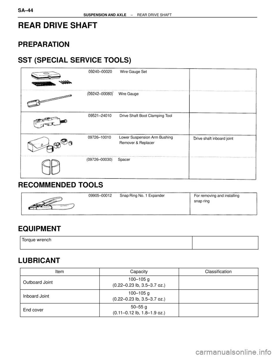
REAR DRIVE SHAFT
PREPARATION
SST (SPECIAL SERVICE TOOLS)
09240±00020 Wire Gauge Set
(09242±00080) Wire Gauge
09521±24010 Drive Shaft Boot Clamping Tool
09726±10010 Lower Suspension Arm Bushing
Remover & Replacer
(09726±00030) Spacer
Drive shaft inboard joint
RECOMMENDED TOOLS
09905±00012 Snap Ring No. 1 ExpanderFor removing and installing
snap ring
EQUIPMENT
�������������������������� �
������������������������� ��������������������������
Torque wrench����������� �
���������� �����������
LUBRICANT
������������� �������������Item������������ ������������Capacity������������� �������������Classification������������� �
������������ ������������� Outboard Joint
������������ �
����������� ������������100±105 g
(0.22±0.23 lb, 3.5±3.7 oz.)������������� �
������������ �������������
������������� �
������������ ������������� Inboard Joint
������������ �
����������� ������������100±105 g
(0.22±0.23 lb, 3.5±3.7 oz.)������������� �
������������ �������������
������������� �
������������ ������������� End cover
������������ �
����������� ������������50±55 g
(0.11±0.12 lb, 1.8±1.9 oz.)������������� �
������������ �������������
SA±44± SUSPENSION AND AXLEREAR DRIVE SHAFT
Page 1832 of 2543
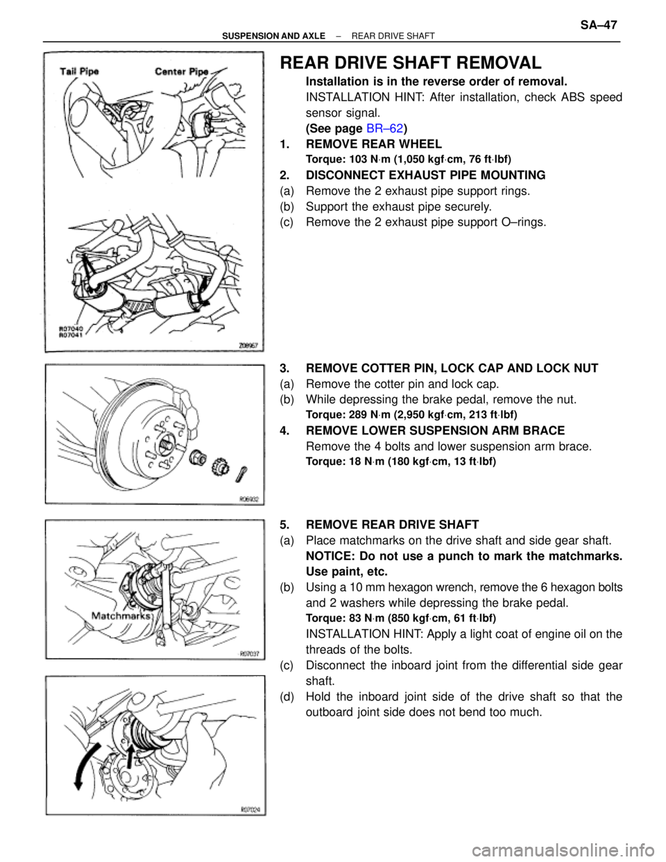
REAR DRIVE SHAFT REMOVAL
Installation is in the reverse order of removal.
INSTALLATION HINT: After installation, check ABS speed
sensor signal.
(See page BR±62)
1. REMOVE REAR WHEEL
Torque: 103 NVm (1,050 kgfVcm, 76 ftVlbf)
2. DISCONNECT EXHAUST PIPE MOUNTING
(a) Remove the 2 exhaust pipe support rings.
(b) Support the exhaust pipe securely.
(c) Remove the 2 exhaust pipe support O±rings.
3. REMOVE COTTER PIN, LOCK CAP AND LOCK NUT
(a) Remove the cotter pin and lock cap.
(b) While depressing the brake pedal, remove the nut.
Torque: 289 NVm (2,950 kgfVcm, 213 ftVlbf)
4. REMOVE LOWER SUSPENSION ARM BRACE
Remove the 4 bolts and lower suspension arm brace.
Torque: 18 NVm (180 kgfVcm, 13 ftVlbf)
5. REMOVE REAR DRIVE SHAFT
(a) Place matchmarks on the drive shaft and side gear shaft.
NOTICE: Do not use a punch to mark the matchmarks.
Use paint, etc.
(b) Using a 10 mm hexagon wrench, remove the 6 hexagon bolts
and 2 washers while depressing the brake pedal.
Torque: 83 NVm (850 kgfVcm, 61 ftVlbf)
INSTALLATION HINT: Apply a light coat of engine oil on the
threads of the bolts.
(c) Disconnect the inboard joint from the differential side gear
shaft.
(d) Hold the inboard joint side of the drive shaft so that the
outboard joint side does not bend too much.
± SUSPENSION AND AXLEREAR DRIVE SHAFTSA±47
Page 1841 of 2543
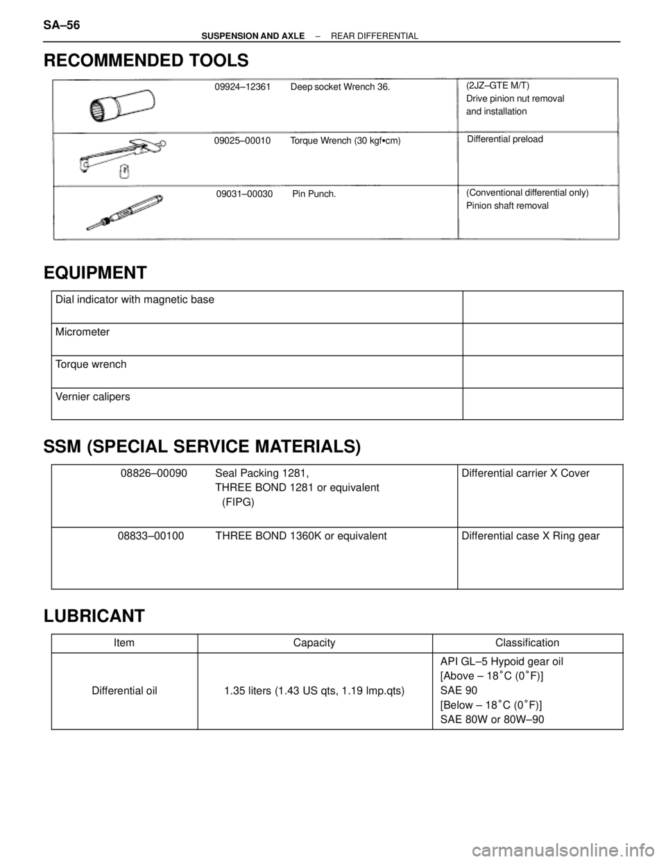
RECOMMENDED TOOLS
09924±12361 Deep socket Wrench 36.
09025±00010 Torque Wrench (30 kgf�cm)
09031±00030 Pin Punch.
(2JZ±GTE M/T)
Drive pinion nut removal
and installation
Differential preload
(Conventional differential only)
Pinion shaft removal
EQUIPMENT
������������������������� �
������������������������ �������������������������
Dial indicator with magnetic base����������� �
���������� �����������
������������������������� �
������������������������ �������������������������
Micrometer����������� �
���������� �����������
������������������������� �
������������������������ �������������������������
Torque wrench����������� �
���������� �����������
������������������������� �
������������������������ �������������������������
Vernier calipers����������� �
���������� �����������
SSM (SPECIAL SERVICE MATERIALS)
������������������������� �
������������������������ �
������������������������ �
������������������������ �������������������������
08826±00090 Seal Packing 1281,
THREE BOND 1281 or equivalent
(FIPG)����������� �
���������� �
���������� �
���������� �����������
Differential carrier X Cover
������������������������� �
������������������������ �
������������������������ �
������������������������ �������������������������
08833±00100 THREE BOND 1360K or equivalent����������� �
���������� �
���������� �
���������� �����������
Differential case X Ring gear
LUBRICANT
��������� �
�������� ���������Item
��������������� �
�������������� ���������������Capacity
������������� �
������������ �������������Classification
��������� �
�������� �
�������� �
�������� ���������
Differential oil
��������������� �
�������������� �
�������������� �
�������������� ���������������
1.35 liters (1.43 US qts, 1.19 lmp.qts)
������������� �
������������ �
������������ �
������������ �������������
API GL±5 Hypoid gear oil
[Above ± 18°C (0°F)]
SAE 90
[Below ± 18°C (0°F)]
SAE 80W or 80W±90
SA±56± SUSPENSION AND AXLEREAR DIFFERENTIAL
Page 1846 of 2543
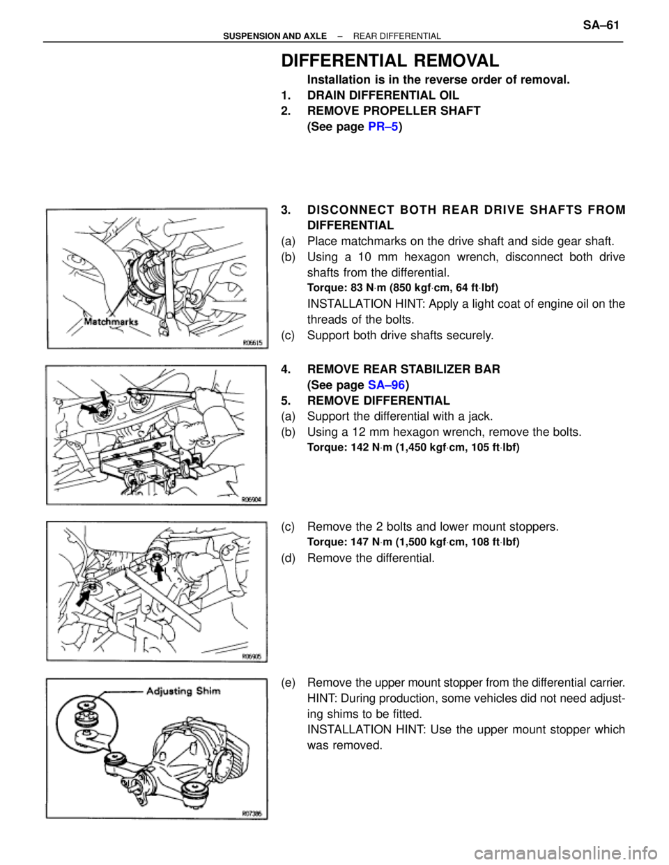
DIFFERENTIAL REMOVAL
Installation is in the reverse order of removal.
1. DRAIN DIFFERENTIAL OIL
2. REMOVE PROPELLER SHAFT
(See page PR±5)
3. DISCONNECT BOTH REAR DRIVE SHAFTS FROM
DIFFERENTIAL
(a) Place matchmarks on the drive shaft and side gear shaft.
(b) Using a 10 mm hexagon wrench, disconnect both drive
shafts from the differential.
Torque: 83 NVm (850 kgfVcm, 64 ftVlbf)
INSTALLATION HINT: Apply a light coat of engine oil on the
threads of the bolts.
(c) Support both drive shafts securely.
4. REMOVE REAR STABILIZER BAR
(See page SA±96)
5. REMOVE DIFFERENTIAL
(a) Support the differential with a jack.
(b) Using a 12 mm hexagon wrench, remove the bolts.
Torque: 142 NVm (1,450 kgfVcm, 105 ftVlbf)
(c) Remove the 2 bolts and lower mount stoppers.
Torque: 147 NVm (1,500 kgfVcm, 108 ftVlbf)
(d) Remove the differential.
(e) Remove the upper mount stopper from the differential carrier.
HINT: During production, some vehicles did not need adjust-
ing shims to be fitted.
INSTALLATION HINT: Use the upper mount stopper which
was removed.
± SUSPENSION AND AXLEREAR DIFFERENTIALSA±61
Page 1850 of 2543
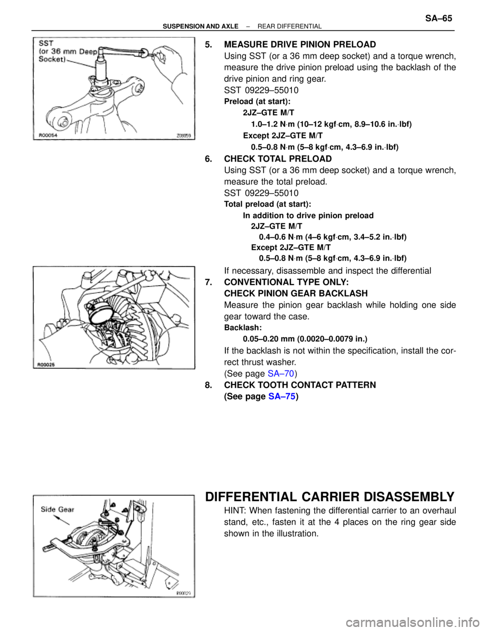
5. MEASURE DRIVE PINION PRELOAD
Using SST (or a 36 mm deep socket) and a torque wrench,
measure the drive pinion preload using the backlash of the
drive pinion and ring gear.
SST 09229±55010
Preload (at start):
2JZ±GTE M/T
1.0±1.2 NVm (10±12 kgfVcm, 8.9±10.6 in.Vlbf)
Except 2JZ±GTE M/T
0.5±0.8 NVm (5±8 kgfVcm, 4.3±6.9 in.Vlbf)
6. CHECK TOTAL PRELOAD
Using SST (or a 36 mm deep socket) and a torque wrench,
measure the total preload.
SST 09229±55010
Total preload (at start):
In addition to drive pinion preload
2JZ±GTE M/T
0.4±0.6 NVm (4±6 kgfVcm, 3.4±5.2 in.Vlbf)
Except 2JZ±GTE M/T
0.5±0.8 NVm (5±8 kgfVcm, 4.3±6.9 in.Vlbf)
If necessary, disassemble and inspect the differential
7. CONVENTIONAL TYPE ONLY:
CHECK PINION GEAR BACKLASH
Measure the pinion gear backlash while holding one side
gear toward the case.
Backlash:
0.05±0.20 mm (0.0020±0.0079 in.)
If the backlash is not within the specification, install the cor-
rect thrust washer.
(See page SA±70)
8. CHECK TOOTH CONTACT PATTERN
(See page SA±75)
DIFFERENTIAL CARRIER DISASSEMBLY
HINT: When fastening the differential carrier to an overhaul
stand, etc., fasten it at the 4 places on the ring gear side
shown in the illustration.
± SUSPENSION AND AXLEREAR DIFFERENTIALSA±65