Page 1692 of 2543
PREPARATION
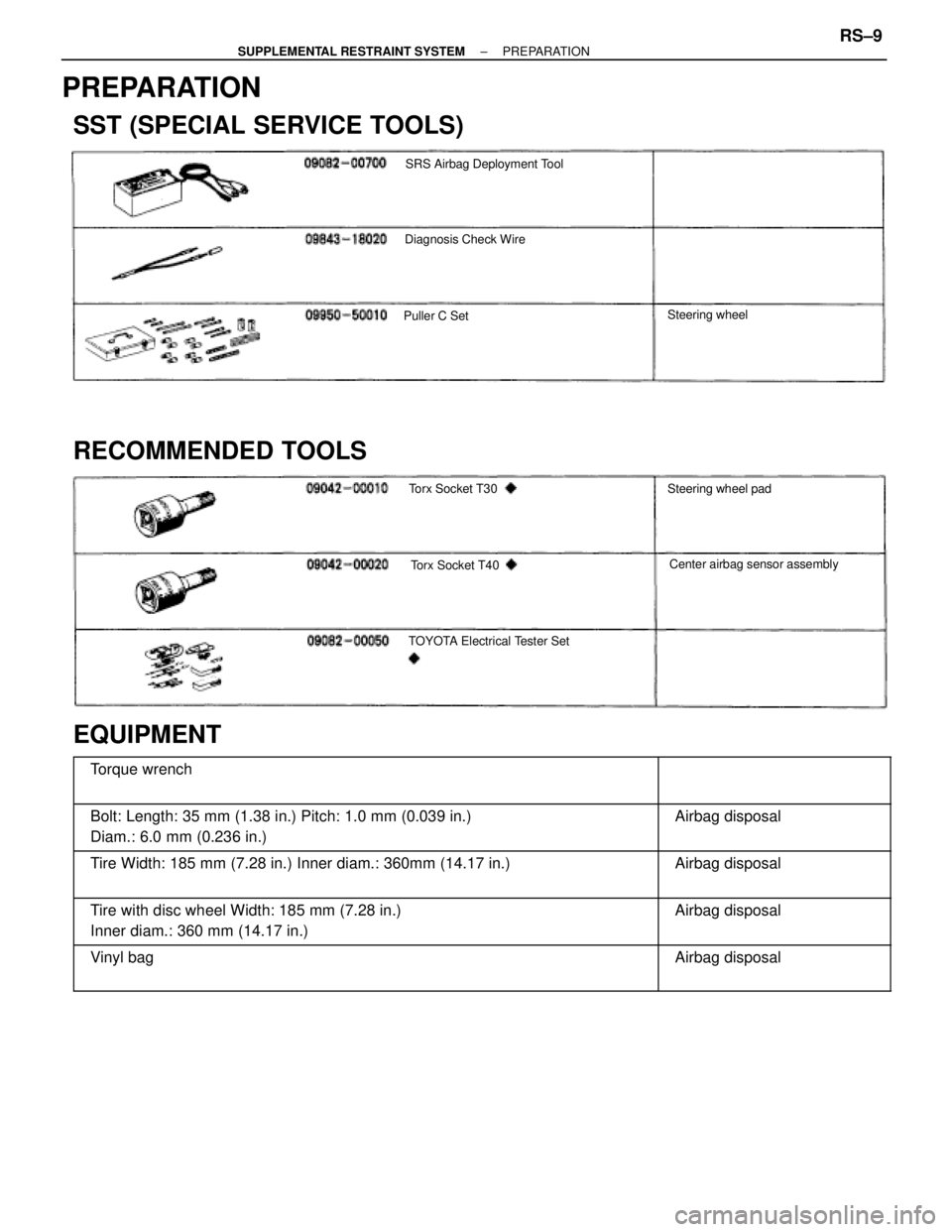
SST (SPECIAL SERVICE TOOLS)
SRS Airbag Deployment Tool
Diagnosis Check Wire
Puller C SetSteering wheel
RECOMMENDED TOOLS
Torx Socket T30
Torx Socket T40
TOYOTA Electrical Tester Set
Steering wheel pad
Center airbag sensor assembly
EQUIPMENT
������������������������� �
������������������������ �������������������������Torque wrench����������� �
���������� �����������
������������������������� �
������������������������ �������������������������Bolt: Length: 35 mm (1.38 in.) Pitch: 1.0 mm (0.039 in.)
Diam.: 6.0 mm (0.236 in.)����������� �
���������� �����������Airbag disposal
������������������������� �
������������������������ �������������������������
Tire Width: 185 mm (7.28 in.) Inner diam.: 360mm (14.17 in.)����������� �
���������� �����������
Airbag disposal
������������������������� �
������������������������ �������������������������
Tire with disc wheel Width: 185 mm (7.28 in.)
Inner diam.: 360 mm (14.17 in.)����������� �
���������� �����������
Airbag disposal
������������������������� �
������������������������ �������������������������
Vinyl bag����������� �
���������� �����������
Airbag disposal
± SUPPLEMENTAL RESTRAINT SYSTEMPREPARATIONRS±9
Page 1706 of 2543
FRONT PASSENGER AIRBAG
ASSEMBLY REMOVAL AND
INSTALLATION
NOTICE:
wIf the wiring connector of the SRS is disconnected with
the ignition switch at ON or ACC, diagnostic trouble
codes will be recorded.
wNever use airbag parts from another vehicle. When
replacing parts, replace with new parts.
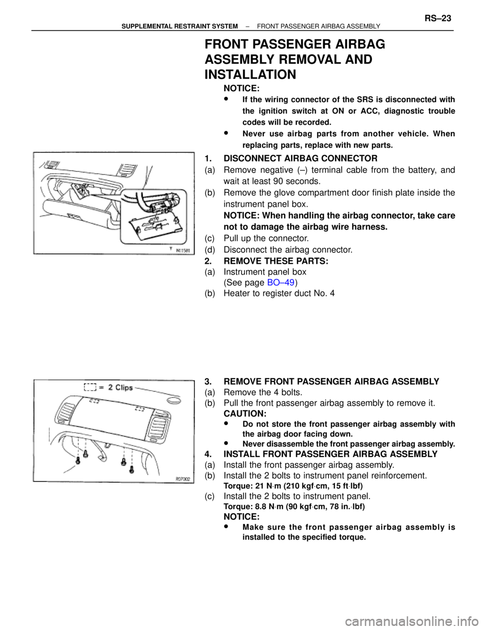
1. DISCONNECT AIRBAG CONNECTOR
(a) Remove negative (±) terminal cable from the battery, and
wait at least 90 seconds.
(b) Remove the glove compartment door finish plate inside the
instrument panel box.
NOTICE: When handling the airbag connector, take care
not to damage the airbag wire harness.
(c) Pull up the connector.
(d) Disconnect the airbag connector.
2. REMOVE THESE PARTS:
(a) Instrument panel box
(See page BO±49)
(b) Heater to register duct No. 4
3. REMOVE FRONT PASSENGER AIRBAG ASSEMBLY
(a) Remove the 4 bolts.
(b) Pull the front passenger airbag assembly to remove it.
CAUTION:
wDo not store the front passenger airbag assembly with
the airbag door facing down.
wNever disassemble the front passenger airbag assembly.
4. INSTALL FRONT PASSENGER AIRBAG ASSEMBLY
(a) Install the front passenger airbag assembly.
(b) Install the 2 bolts to instrument panel reinforcement.
Torque: 21 NVm (210 kgfVcm, 15 ftVlbf)
(c) Install the 2 bolts to instrument panel.
Torque: 8.8 NVm (90 kgfVcm, 78 in.Vlbf)
NOTICE:
wMake sure the front passenger airbag assembly is
installed to the specified torque.
± SUPPLEMENTAL RESTRAINT SYSTEMFRONT PASSENGER AIRBAG ASSEMBLYRS±23
Page 1715 of 2543
1. REMOVE FRONT FENDER LINER AND HEADLIGHT
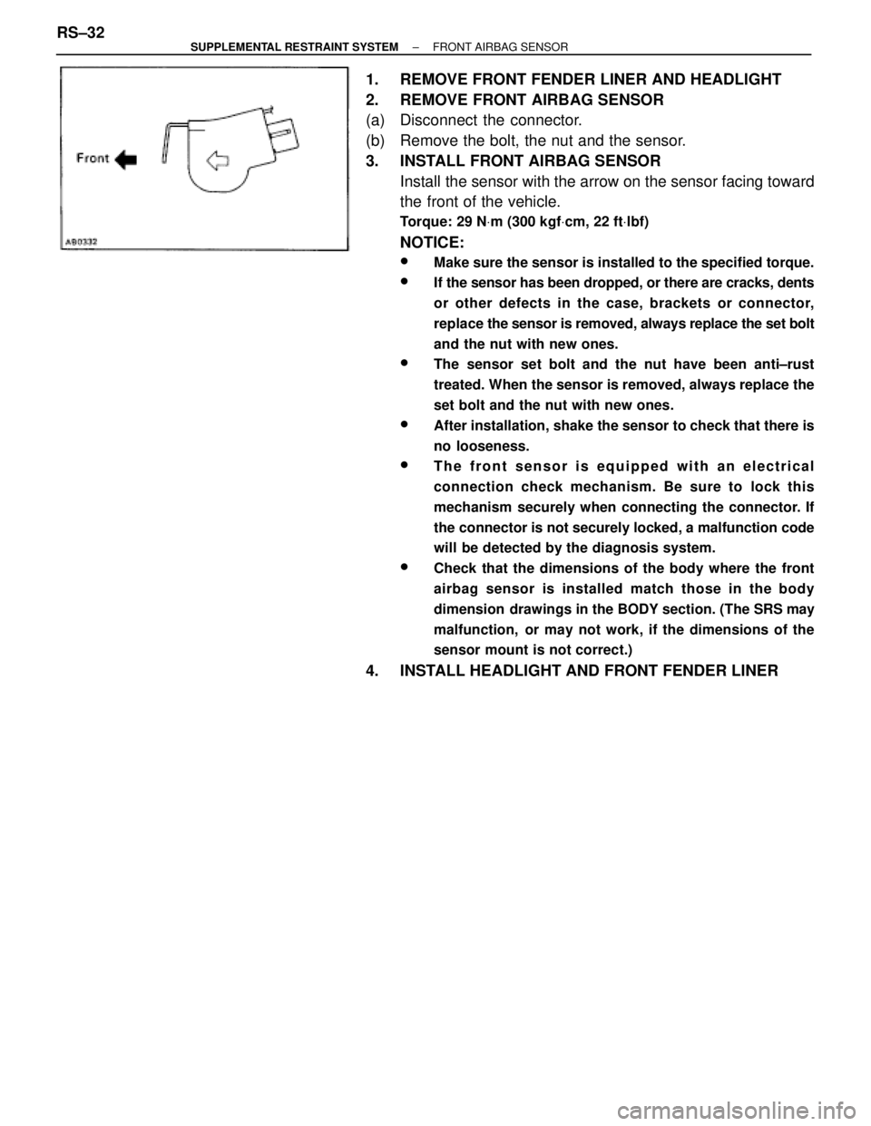
2. REMOVE FRONT AIRBAG SENSOR
(a) Disconnect the connector.
(b) Remove the bolt, the nut and the sensor.
3. INSTALL FRONT AIRBAG SENSOR
Install the sensor with the arrow on the sensor facing toward
the front of the vehicle.
Torque: 29 NVm (300 kgfVcm, 22 ftVlbf)
NOTICE:
wMake sure the sensor is installed to the specified torque.
wIf the sensor has been dropped, or there are cracks, dents
or other defects in the case, brackets or connector,
replace the sensor is removed, always replace the set bolt
and the nut with new ones.
wThe sensor set bolt and the nut have been anti±rust
treated. When the sensor is removed, always replace the
set bolt and the nut with new ones.
wAfter installation, shake the sensor to check that there is
no looseness.
wThe front sensor is equipped with an electrical
connection check mechanism. Be sure to lock this
mechanism securely when connecting the connector. If
the connector is not securely locked, a malfunction code
will be detected by the diagnosis system.
wCheck that the dimensions of the body where the front
airbag sensor is installed match those in the body
dimension drawings in the BODY section. (The SRS may
malfunction, or may not work, if the dimensions of the
sensor mount is not correct.)
4. INSTALL HEADLIGHT AND FRONT FENDER LINER RS±32
± SUPPLEMENTAL RESTRAINT SYSTEMFRONT AIRBAG SENSOR
Page 1718 of 2543
wNever use SRS parts from another vehicle. When
replacing parts, replace with new parts.
wNever reuse the center airbag sensor assembly involved
in a collision when the airbag has deployed.
wNever repair a sensor in order to reuse it.
1. REMOVE CONSOLE PANEL UPPER AND CONSOLE BOX
(See page BO±44)
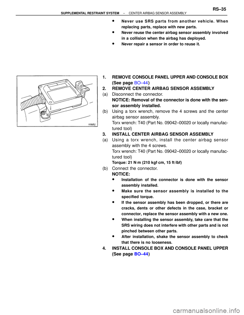
2. REMOVE CENTER AIRBAG SENSOR ASSEMBLY
(a) Disconnect the connector.
NOTICE: Removal of the connector is done with the sen-
sor assembly installed.
(b) Using a torx wrench, remove the 4 screws and the center
airbag sensor assembly.
Torx wrench: T40 (Part No. 09042±00020 or locally manufac-
tured tool)
3. INSTALL CENTER AIRBAG SENSOR ASSEMBLY
(a) Usin g a to rx wre n ch , in sta ll th e ce n te r airb a g se n so r
assembly with the 4 screws.
Torx wrench: T40 (Part No. 09042±00020 or locally manufac-
tured tool)
Torque: 21 NVm (210 kgfVcm, 15 ftVlbf)
(b) Connect the connector.
NOTICE:
wInstallation of the connector is done with the sensor
assembly installed.
wMake sure the sensor assembly is installed to the
specified torque.
wIf the sensor assembly has been dropped, or there are
cracks, dents or other defects in the case, bracket or
connector, replace the sensor assembly with a new one.
wWhen installing the sensor assembly, take care that the
SRS wiring does not interfere with other parts and is not
pinched between other parts.
wAfter installation, shake the sensor assembly to check
that there is no looseness.
4. INSTALL CONSOLE BOX AND CONSOLE PANEL UPPER
(See page BO±44)
± SUPPLEMENTAL RESTRAINT SYSTEMCENTER AIRBAG SENSOR ASSEMBLYRS±35
Page 1785 of 2543
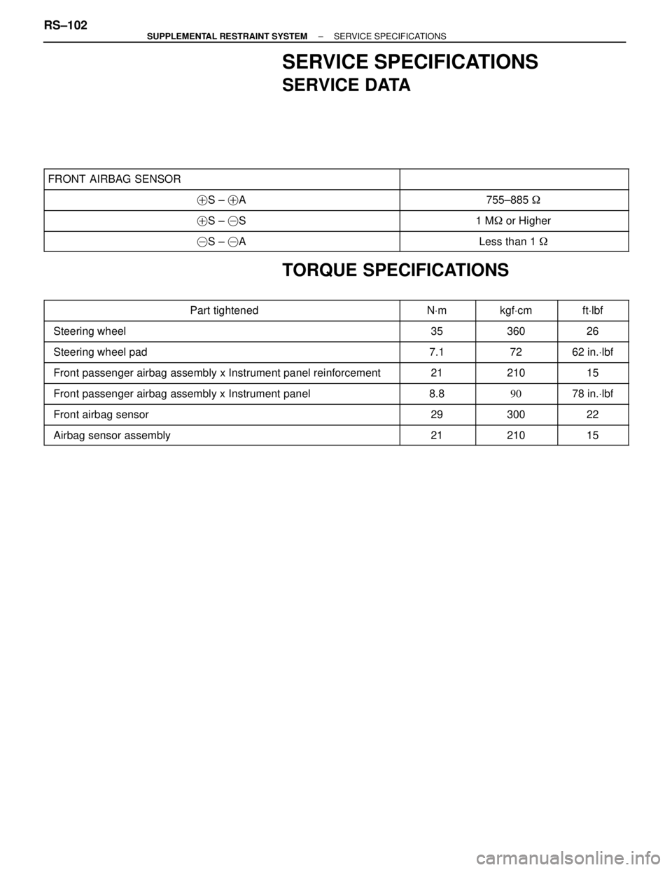
SERVICE SPECIFICATIONS
SERVICE DATA
���������������������� �
��������������������� ����������������������FRONT AIRBAG SENSOR
��������������� �
�������������� ���������������
���������������������� �����������������������S ± �A��������������� ���������������755±885 �
���������������������� �����������������������S ± �S��������������� ���������������1 M� or Higher
���������������������� �����������������������S ± �A��������������� ���������������Less than 1 �
TORQUE SPECIFICATIONS
���������������������� �
���������������������Part tightened������ �
�����NVm������ �
�����kgfVcm����� �
����ftVlbf���������������������� �
��������������������� ����������������������Steering wheel
������ �
����� ������35
������ �
����� ������360
����� �
���� �����26
���������������������� ����������������������Steering wheel pad������ ������7.1������ ������72����� �����62 in.Vlbf
���������������������� ����������������������Front passenger airbag assembly x Instrument panel reinforcement������ ������21������ ������210����� �����15
���������������������� ����������������������Front passenger airbag assembly x Instrument panel������ ������8.8������ ������90����� �����78 in.Vlbf���������������������� �
��������������������� ����������������������Front airbag sensor
������ �
����� ������29
������ �
����� ������300
����� �
���� �����22
���������������������� ����������������������Airbag sensor assembly������ ������21������ ������210����� �����15
RS±102± SUPPLEMENTAL RESTRAINT SYSTEMSERVICE SPECIFICATIONS
Page 1790 of 2543
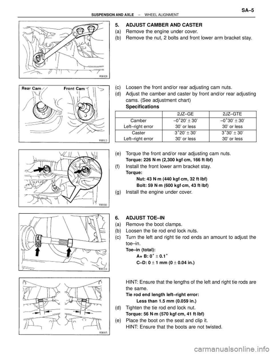
5. ADJUST CAMBER AND CASTER
(a) Remove the engine under cover.
(b) Remove the nut, 2 bolts and front lower arm bracket stay.
(c) Loosen the front and/or rear adjusting cam nuts.
(d) Adjust the camber and caster by front and/or rear adjusting
cams. (See adjustment chart)
Specifications
�������� ���������������� ��������2JZ±GE�������� ��������2JZ±GTE
�������� ��������Camber
Left±right error�������� ��������±0°20' + 30'
30' or less�������� ��������±0°30' + 30'
30' or less
�������� �
������� ��������Caster
Left±right error�������� �
������� ��������3°20' + 30'
30' or less�������� �
������� ��������3°30' + 30'
30' or less
(e) Torque the front and/or rear adjusting cam nuts.
Torque: 226 NVm (2,300 kgfVcm, 166 ftVlbf)
(f) Install the front lower arm bracket stay.
Torque:
Nut: 43 NVm (440 kgfVcm, 32 ftVlbf)
Bolt: 59 NVm (600 kgfVcm, 43 ftVlbf)
(g) Install the engine under cover.
6. ADJUST TOE±IN
(a) Remove the boot clamps.
(b) Loosen the tie rod end lock nuts.
(c) Turn the left and right tie rod ends an amount to adjust the
toe±in.
Toe±in (total):
A+ B: 0° + 0.1°
C±D: 0 + 1 mm (0 + 0.04 in.)
HINT: Ensure that the lengths of the left and right tie rods are
the same.
Tie rod end length left±right error:
Less than 1.5 mm (0.059 in.)
(d) Tighten the tie rod end lock nut.
Torque: 56 NVm (570 kgfVcm, 41 ftVlbf)
(e) Place the boot on the seat and clip it.
HINT: Ensure that the boots are not twisted.
± SUSPENSION AND AXLEWHEEL ALIGNMENTSA±5
Page 1795 of 2543
(c) Remove the bolt and disconnect the parking brake cable
bracket.
(d) Loosen and adjust the No.1 and/or No.2 cams.
(e) Adjust camber and toe±in by turning the No.1 and / or No.2
cams.
(See adjustment chart)
(f) Torque the No.1 and/or No.2 cam nuts.
Torque: 184 NVm (1,880 kgfVcm, 134 ftVlbf)
(g) Connect the parking brake cable bracket with the bolt. SA±10
± SUSPENSION AND AXLEWHEEL ALIGNMENT
Page 1799 of 2543
RECOMMENDED TOOLS
���������� �
��������� �
��������� ����������
������������������� �
������������������ �
������������������ �������������������
09905±00013 Snap Ring Pliers.��������� �
�������� �
�������� ���������
Front axle hub bearing
EQUIPMENT
���������������������������� �
��������������������������� ����������������������������
Dial indicator��������� �
�������� ���������
���������������������������� �
��������������������������� ����������������������������
Torque wrench��������� �
�������� ���������
SA±14± SUSPENSION AND AXLEFRONT AXLE HUB