Page 1576 of 2543
PRECAUTIONS
1. Always use new gaskets when replacing the fuel tank or
component parts.
2. Apply the proper torque to all parts tightened.
FUEL LINES AND CONNECTIONS
INSPECTION
(a) Check the fuel lines for cracks or leakage, and all
connections for deformation.
(b) C h e c k t h e f u e l t a n k vapor vent system hoses and
connections for looseness, sharp bends or damage.
(c) Check the fuel tank for deformation, cracks, fuel leakage or
tank band looseness.
(d) Check the filler neck for damage or fuel leakage.
(e) Hose and tube connections are as shown in the illustration.
If a problem is found, repair or replace the part as necessary. EG±286
± ENGINESFI SYSTEM (2JZ±GTE)
Page 1577 of 2543
MAS AIR FLOW (MAF) METER
COMPONENTS FOR REMOVAL AND
INSTALLATION
MAF METER REMOVAL
Installation is in the reverse order of removal.
1. REMOVE NO.1 AIR HOSE
2. REMOVE AIR CLEANER HOSE
3. REMOVE MAF METER
(a) Remove the 2 bolts, and disconnect the MAF meter from the
air cleaner case.
Torque: 6.9 NVm (70 kgfVcm, 61 in.Vlbf)
(b) Disconnect the MAF meter wire from the wire clamp on the
air cleaner case.
(c) Disconnect the MAF meter connector, and remove the MAF
meter.
± ENGINESFI SYSTEM (2JZ±GTE)EG±287
Page 1581 of 2543

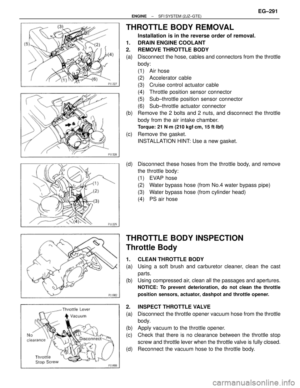
THROTTLE BODY REMOVAL
Installation is in the reverse order of removal.
1. DRAIN ENGINE COOLANT
2. REMOVE THROTTLE BODY
(a) Disconnect the hose, cables and connectors from the throttle
body:
(1) Air hose
(2) Accelerator cable
(3) Cruise control actuator cable
(4) Throttle position sensor connector
(5) Sub±throttle position sensor connector
(6) Sub±throttle actuator connector
(b) Remove the 2 bolts and 2 nuts, and disconnect the throttle
body from the air intake chamber.
Torque: 21 NVm (210 kgfVcm, 15 ftVlbf)
(c) Remove the gasket.
INSTALLATION HINT: Use a new gasket.
(d) Disconnect these hoses from the throttle body, and remove
the throttle body:
(1) EVAP hose
(2) Water bypass hose (from No.4 water bypass pipe)
(3) Water bypass hose (from cylinder head)
(4) PS air hose
THROTTLE BODY INSPECTION
Throttle Body
1. CLEAN THROTTLE BODY
(a) Using a soft brush and carburetor cleaner, clean the cast
parts.
(b) Using compressed air, clean all the passages and apertures.
NOTICE: To prevent deterioration, do not clean the throttle
position sensors, actuator, dashpot and throttle opener.
2. INSPECT THROTTLE VALVE
(a) Disconnect the throttle opener vacuum hose from the throttle
body.
(b) Apply vacuum to the throttle opener.
(c) Check that there is no clearance between the throttle stop
screw and throttle lever when the throttle valve is fully closed.
(d) Reconnect the vacuum hose to the throttle body.
± ENGINESFI SYSTEM (2JZ±GTE)EG±291
Page 1588 of 2543

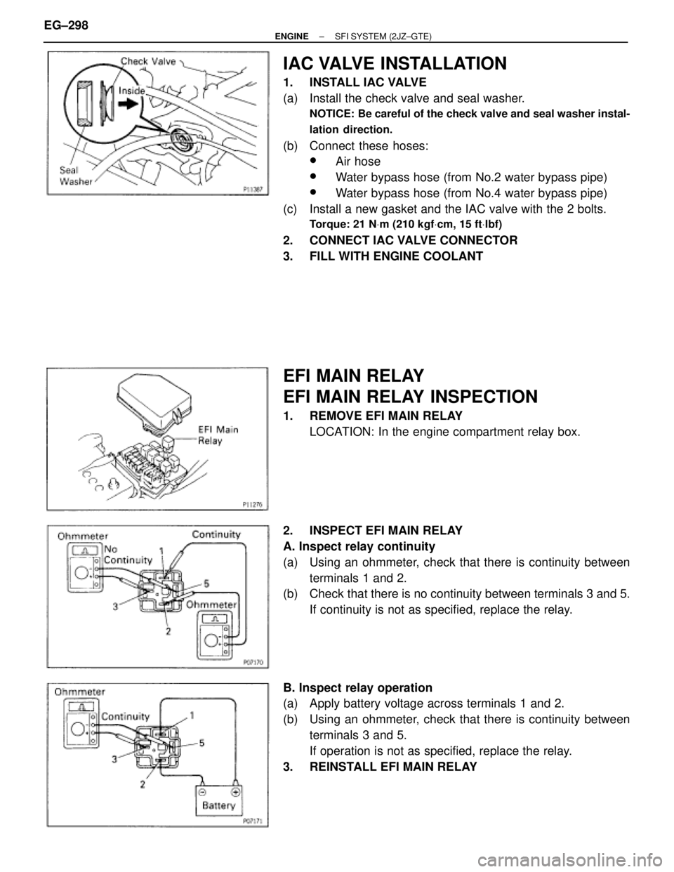
IAC VALVE INSTALLATION
1. INSTALL IAC VALVE
(a) Install the check valve and seal washer.
NOTICE: Be careful of the check valve and seal washer instal-
lation direction.
(b) Connect these hoses:
wAir hose
wWater bypass hose (from No.2 water bypass pipe)
wWater bypass hose (from No.4 water bypass pipe)
(c) Install a new gasket and the IAC valve with the 2 bolts.
Torque: 21 NVm (210 kgfVcm, 15 ftVlbf)
2. CONNECT IAC VALVE CONNECTOR
3. FILL WITH ENGINE COOLANT
EFI MAIN RELAY
EFI MAIN RELAY INSPECTION
1. REMOVE EFI MAIN RELAY
LOCATION: In the engine compartment relay box.
2. INSPECT EFI MAIN RELAY
A. Inspect relay continuity
(a) Using an ohmmeter, check that there is continuity between
terminals 1 and 2.
(b) Check that there is no continuity between terminals 3 and 5.
If continuity is not as specified, replace the relay.
B. Inspect relay operation
(a) Apply battery voltage across terminals 1 and 2.
(b) Using an ohmmeter, check that there is continuity between
terminals 3 and 5.
If operation is not as specified, replace the relay.
3. REINSTALL EFI MAIN RELAY EG±298
± ENGINESFI SYSTEM (2JZ±GTE)
Page 1603 of 2543
EGR GAS TEMPERATURE SENSOR
COMPONENTS FOR REMOVAL AND
INSTALLATION
EGR GAS TEMPERATURE SENSOR
INSPECTION
1. REMOVE EGR GAS TEMPERATURE SENSOR
2. INSPECT EGR GAS TEMPERATURE SENSOR
Using an ohmmeter, measure the resistance between the ter-
minals.
Resistance:
At 50°C (112°F)
64±97 k�
At 100°C (212°F)
11±16 k �
At 150°C (302°F)
2±4 k �
If the resistance is not as specified, replace the sensor.
Torque: 20 NVm (200 kgfVcm, 14 ftVlbf)
3. REINSTALL EGR GAS TEMPERATURE SENSOR
± ENGINESFI SYSTEM (2JZ±GTE)EG±313
Page 1607 of 2543
KNOCK SENSORS INSPECTION
1. REMOVE THROTTLE BODY
(See throttle body removal)
2. REMOVE STARTER
(See starter removal in Starting System)
3. REMOVE KNOCK SENSORS
(a) Disconnect the knock sensor connector.
(b) Using SST, remove the knock sensor.
SST 09816±30010
4. INSPECT KNOCK SENSORS
Using an ohmmeter, check that there is no continuity be-
tween the terminal and body.
If there is continuity, replace the sensor.
5. REINSTALL KNOCK SENSORS
(a) Using SST, install the knock sensor.
SST 09816±30010
Torque: 44 NVm (450 kgfVcm, 33 ftVlbf)
(b) Connect the knock sensor connector.
6. REINSTALL STARTER
(See starter installation in Starting System)
7. REINSTALL THROTTLE BODY
(See throttle body installation)
± ENGINESFI SYSTEM (2JZ±GTE)EG±317
Page 1610 of 2543
3. INSPECT HEATER RESISTANCE OF MAIN HEATED
OXYGEN SENSOR
(a) Disconnect the oxygen sensor connector.
(b) Using an ohmmeter, measure the resistance between the
terminals +B and HT.
Resistance:
At 20°C (68°F) 11±16 �
If the resistance is not as specified, replace the sensor.
Torque: 20 NVm (200 kgfVcm, 14 ftVlbf)
(c) Reconnect the oxygen sensor connector. EG±320
± ENGINESFI SYSTEM (2JZ±GTE)
Page 1612 of 2543
OXYGEN SENSOR INSPECTION
1. INSPECT OPERATION OF SUB HEATED OXYGEN
SENSOR
(See circuit inspection in Engine Troubleshooting)
2. INSPECT HEATER RESISTANCE OF SUB HEATED
OXYGEN SENSOR
(a) Remove the driver's seat.
(b) Take out the console box side of the floor carpet.
(c) Disconnect the oxygen sensor connector.
(d) Using an ohmmeter, measure the resistance between the
terminals +B and HT.
Resistance:
At 20°C (68°F) 11±16 �
If the resistance is not as specified, replace the sensor.
Torque: 20 NVm (200 kgfVcm, 14 ftVlbf)
(e) Reconnect the oxygen sensor connector.
(f) Reinstall the floor carpet.
(g) Reinstall the driver's seat. EG±322
± ENGINESFI SYSTEM (2JZ±GTE)