Page 1509 of 2543

THROTTLE BODY
ON±VEHICLE INSPECTION
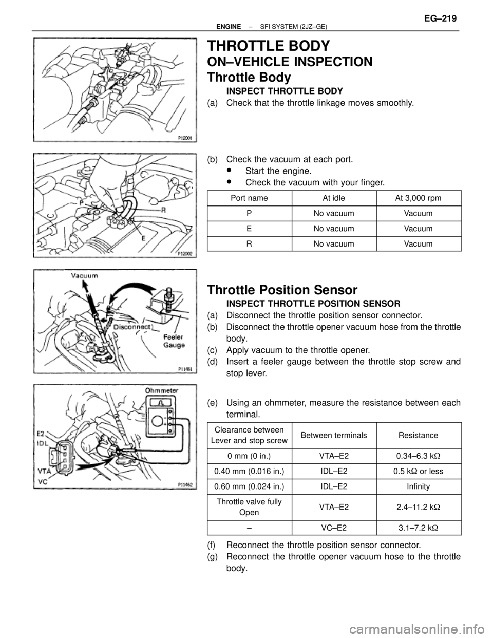
Throttle Body
INSPECT THROTTLE BODY
(a) Check that the throttle linkage moves smoothly.
(b) Check the vacuum at each port.
wStart the engine.
wCheck the vacuum with your finger.
�������� ��������Port name�������� ��������At idle�������� ��������At 3,000 rpm
�������� ��������P�������� ��������No vacuum�������� ��������Vacuum�������� �
������� ��������E
�������� �
������� ��������No vacuum
�������� �
������� ��������Vacuum
�������� ��������R�������� ��������No vacuum�������� ��������Vacuum
Throttle Position Sensor
INSPECT THROTTLE POSITION SENSOR
(a) Disconnect the throttle position sensor connector.
(b) Disconnect the throttle opener vacuum hose from the throttle
body.
(c) Apply vacuum to the throttle opener.
(d) Insert a feeler gauge between the throttle stop screw and
stop lever.
(e) Using an ohmmeter, measure the resistance between each
terminal.
�������� �
������� ��������
Clearance between
Lever and stop screw�������� �
������� ��������Between terminals�������� �
������� ��������Resistance
�������� ��������0 mm (0 in.)�������� ��������VTA±E2�������� ��������0.34±6.3 k�
�������� ��������0.40 mm (0.016 in.)�������� ��������IDL±E2�������� ��������0.5 k� or less
�������� ��������0.60 mm (0.024 in.)�������� ��������IDL±E2�������� ��������Infinity�������� �
������� �
������� ��������
Throttle valve fully
Open
�������� �
������� �
������� ��������
VTA±E2
�������� �
������� �
������� ��������
2.4±11.2 k�
�������� ��������±�������� ��������VC±E2�������� ��������3.1±7.2 k�
(f) Reconnect the throttle position sensor connector.
(g) Reconnect the throttle opener vacuum hose to the throttle
body.
± ENGINESFI SYSTEM (2JZ±GE)EG±219
Page 1512 of 2543

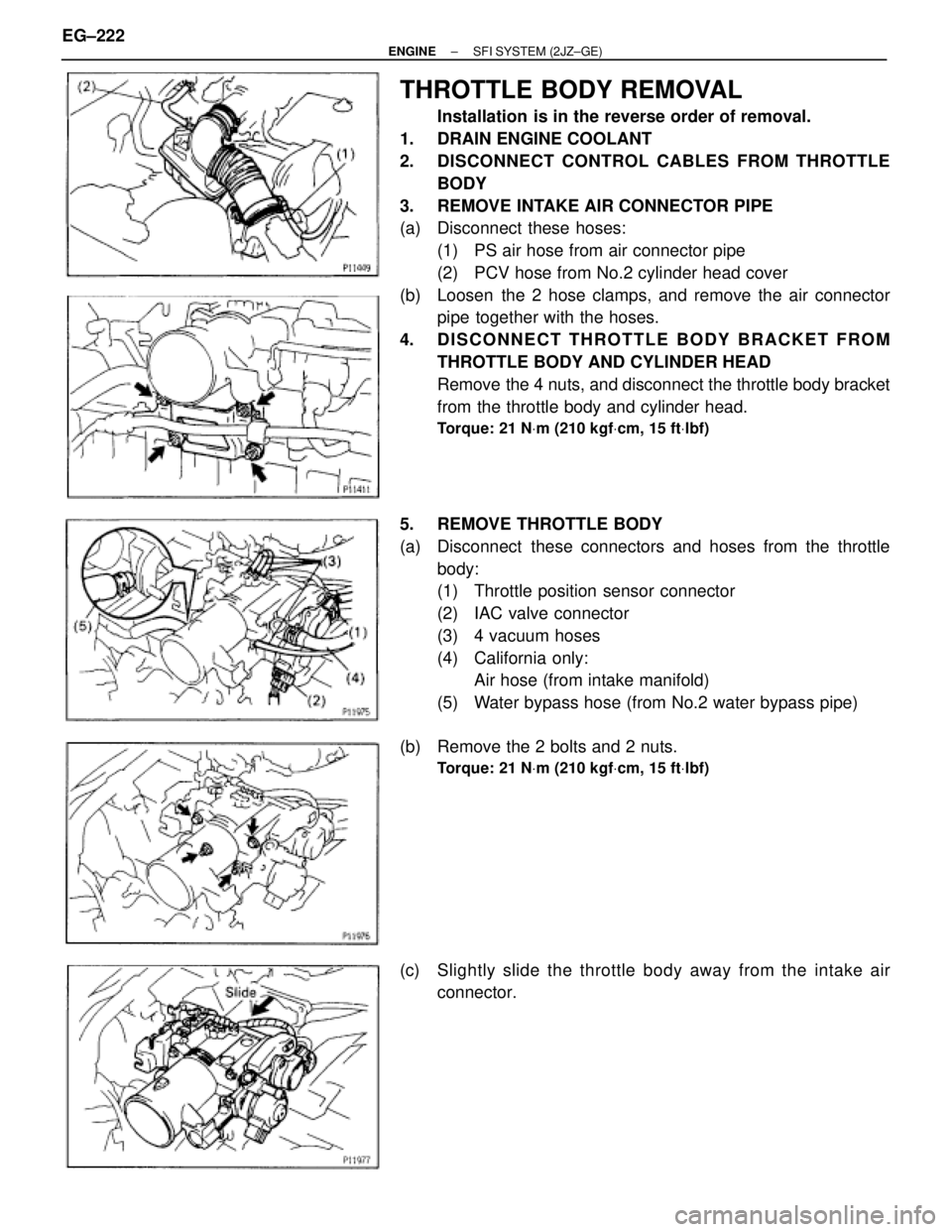
THROTTLE BODY REMOVAL
Installation is in the reverse order of removal.
1. DRAIN ENGINE COOLANT
2. DISCONNECT CONTROL CABLES FROM THROTTLE
BODY
3. REMOVE INTAKE AIR CONNECTOR PIPE
(a) Disconnect these hoses:
(1) PS air hose from air connector pipe
(2) PCV hose from No.2 cylinder head cover
(b) Loosen the 2 hose clamps, and remove the air connector
pipe together with the hoses.
4. DISCONNECT THROTTLE BODY BRACKET FROM
THROTTLE BODY AND CYLINDER HEAD
Remove the 4 nuts, and disconnect the throttle body bracket
from the throttle body and cylinder head.
Torque: 21 NVm (210 kgfVcm, 15 ftVlbf)
5. REMOVE THROTTLE BODY
(a) Disconnect these connectors and hoses from the throttle
body:
(1) Throttle position sensor connector
(2) IAC valve connector
(3) 4 vacuum hoses
(4) California only:
Air hose (from intake manifold)
(5) Water bypass hose (from No.2 water bypass pipe)
(b) Remove the 2 bolts and 2 nuts.
Torque: 21 NVm (210 kgfVcm, 15 ftVlbf)
(c) Slightly slide the throttle body away from the intake air
connector. EG±222
± ENGINESFI SYSTEM (2JZ±GE)
Page 1513 of 2543

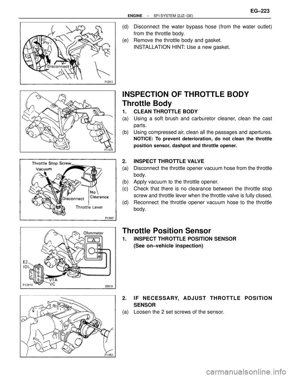
(d) Disconnect the water bypass hose (from the water outlet)
from the throttle body.
(e) Remove the throttle body and gasket.
INSTALLATION HINT: Use a new gasket.
INSPECTION OF THROTTLE BODY
Throttle Body
1. CLEAN THROTTLE BODY
(a) Using a soft brush and carburetor cleaner, clean the cast
parts.
(b) Using compressed air, clean all the passages and apertures.
NOTICE: To prevent deterioration, do not clean the throttle
position sensor, dashpot and throttle opener.
2. INSPECT THROTTLE VALVE
(a) Disconnect the throttle opener vacuum hose from the throttle
body.
(b) Apply vacuum to the throttle opener.
(c) Check that there is no clearance between the throttle stop
screw and throttle lever when the throttle valve is fully closed.
(d) Reconnect the throttle opener vacuum hose to the throttle
body.
Throttle Position Sensor
1. INSPECT THROTTLE POSITION SENSOR
(See on±vehicle inspection)
2. IF NECESSARY, ADJUST THROTTLE POSITION
SENSOR
(a) Loosen the 2 set screws of the sensor.
± ENGINESFI SYSTEM (2JZ±GE)EG±223
Page 1514 of 2543
(b) Insert a 0.50 mm (0.020 in.) feeler gauge between the throttle
stop screw and stop lever.
(c) Connect the tester probe of an ohmmeter to the terminals IDL
and E2 of the sensor.
(d) Gradually turn the sensor clockwise until the ohmmeter
deflects, and secure it with the 2 set screws.
(e) Recheck the continuity between terminals IDL and E2.
����������� �
���������� �
���������� �����������
Clearance between
lever and stop screw
������������ �
����������� �
����������� ������������
Continuity (IDL±E2)
����������� �����������0.40 mm (0.016 in.)������������ ������������Continuity
����������� �����������0.60 mm (0.024 in.)������������ ������������No continuity
EG±224± ENGINESFI SYSTEM (2JZ±GE)
Page 1522 of 2543

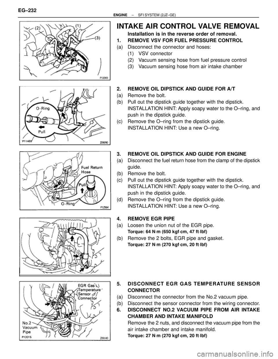
INTAKE AIR CONTROL VALVE REMOVAL
Installation is in the reverse order of removal.
1. REMOVE VSV FOR FUEL PRESSURE CONTROL
(a) Disconnect the connector and hoses:
(1) VSV connector
(2) Vacuum sensing hose from fuel pressure control
(3) Vacuum sensing hose from air intake chamber
2. REMOVE OIL DIPSTICK AND GUIDE FOR A/T
(a) Remove the bolt.
(b) Pull out the dipstick guide together with the dipstick.
INSTALLATION HINT: Apply soapy water to the O±ring, and
push in the dipstick guide.
(c) Remove the O±ring from the dipstick guide.
INSTALLATION HINT: Use a new O±ring.
3. REMOVE OIL DIPSTICK AND GUIDE FOR ENGINE
(a) Disconnect the fuel return hose from the clamp of the dipstick
guide.
(b) Remove the bolt.
(c) Pull out the dipstick guide together with the dipstick.
INSTALLATION HINT: Apply soapy water to the O±ring, and
push in the dipstick guide.
(d) Remove the O±ring from the dipstick guide.
INSTALLATION HINT: Use a new O±ring.
4. REMOVE EGR PIPE
(a) Loosen the union nut of the EGR pipe.
Torque: 64 NVm (650 kgfVcm, 47 ftVlbf)
(b) Remove the 2 bolts, EGR pipe and gasket.
Torque: 27 NVm (270 kgfVcm, 20 ftVlbf)
5. DISCONNECT EGR GAS TEMPERATURE SENSOR
CONNECTOR
(a) Disconnect the connector from the No.2 vacuum pipe.
(b) Disconnect the sensor connector from the wiring connector.
6. DISCONNECT NO.2 VACUUM PIPE FROM AIR INTAKE
CHAMBER AND INTAKE MANIFOLD
Remove the 2 nuts, and disconnect the vacuum pipe from the
air intake chamber and intake manifold.
Torque: 27 NVm (270 kgfVcm, 20 ftVlbf)
EG±232± ENGINESFI SYSTEM (2JZ±GE)
Page 1532 of 2543
ENGINE COOLANT TEMPERATURE
(ECT) SENSOR
COMPONENTS FOR REMOVAL AND
INSTALLATION
ECT SENSOR INSPECTION
1. DRAIN ENGINE COOLANT
2. REMOVE ECT SENSOR
(a) Disconnect the ECT sensor connector.
(b) Using SST, remove the ECT sensor and gasket.
SST 09205±76030 EG±242
± ENGINESFI SYSTEM (2JZ±GE)
Page 1533 of 2543
3. INSPECT ECT SENSOR
Using an ohmmeter, measure the resistance between the ter-
minals.
Resistance:
Refer to the graph
If the resistance is not as specified, replace the ECT sensor.
4. REINSTALL ECT SENSOR
(a) Install a new gasket to the ECT sensor.
(b) Using SST, install the ECT sensor.
SST 09205±76030
(c) Connect the ECT sensor connector.
5. REFILL WITH ENGINE COOLANT
± ENGINESFI SYSTEM (2JZ±GE)EG±243
Page 1534 of 2543
EGR GAS TEMPERATURE SENSOR
COMPONENTS FOR REMOVAL AND
INSTALLATION
EGR GAS TEMPERATURE SENSOR
INSPECTION
1. REMOVE EGR GAS TEMPERATURE SENSOR
2. INSPECT EGR GAS TEMPERATURE SENSOR
Using an ohmmeter, measure the resistance between the ter-
minals.
Resistance:
At 50°C (112°F)
64±97 k�
At 100°C (212°F)
11±16 k�
At 150°C (302°F)
2±4 k�
If the resistance is not as specified, replace the sensor.
Torque: 20 NVm (200 kgfVcm, 14 ftVlbf)
3. REINSTALL EGR GAS TEMPERATURE SENSOR EG±244
± ENGINESFI SYSTEM (2JZ±GE)